
IN THIS CHAPTER, YOU WILL LEARN ABOUT THE FOLLOWING:
- Wireless networking topologies
- Wireless wide area network (WWAN)
- Wireless metropolitan area network (WMAN)
- Wireless personal area network (WPAN)
- Wireless local area network (WLAN)
- 802.11 topologies
- Access point
- Client station
- Integration service (IS)
- Distribution system (DS)
- Wireless distribution system (WDS)
- Service set identifier (SSID)
- Basic service set (BSS)
- Basic service set identifier (BSSID)
- Basic service area (BSA)
- Extended service set (ESS)
- Independent basic service set (IBSS)
- Mesh basic service set (MBSS)
- QoS basic service set (QoS BSS)
- 802.11 configuration modes
- Access point modes
- Client station modes
 A computer network is a system that provides communications between computers. Computer networks can be configured as peer to peer, as client-server, or as clustered central processing units (CPUs) with distributed dumb terminals. A networking topology is defined simply as the physical and/or logical layout of nodes in a computer network. Any individual who has taken a networking basics class is already familiar with the bus, ring, star, mesh, and hybrid topologies that are often used in wired networks.
All topologies have advantages and disadvantages. A topology may cover very small areas or can exist as a worldwide architecture. Wireless topologies also exist as defined by the physical and logical layout of wireless hardware. Many wireless technologies are available and can be arranged into four major wireless networking topologies. The 802.11-2012 standard defines one specific type of wireless communication. Within the 802.11 standard are four types of topologies, known as service sets. Over the years, vendors have also used 802.11 hardware using variations of these topologies to meet specific wireless networking needs. This chapter covers the topologies used by a cross section of RF technologies and covers 802.11-specific WLAN topologies.
Wireless Networking Topologies
Although the main focus of this study guide is 802.11 wireless networking, which is a local area technology, other wireless technologies and standards exist in which wireless communications span either smaller or larger areas of coverage. Examples of other wireless technologies are cellular, Bluetooth, and ZigBee. All of these different wireless technologies can be arranged into four major wireless topologies:
- Wireless wide area network (WWAN)
- Wireless metropolitan area network (WMAN)
- Wireless personal area network (WPAN)
- Wireless local area network (WLAN)
Additionally, although the 802.11-2012 standard is a WLAN standard, the same technology can sometimes be deployed in different wireless network architectures, as discussed in the following sections.
Wireless Wide Area Network (WWAN)
A wide area network (WAN) provides RF coverage over a vast geographical area. A WAN might traverse an entire state, region, or country or even span worldwide. The best example of a WAN is the Internet. Many private and public corporate WANs consist of hardware infrastructure such as T1 lines, fiber optics, and routers. Protocols used for wired WAN communications include Frame Relay, ATM, Multiprotocol Label Switching (MPLS), and others.
A wireless wide area network (WWAN) also covers broad geographical boundaries but obviously uses a wireless medium instead of a wired medium. WWANs typically use cellular telephone technologies or proprietary licensed wireless bridging technologies. Cellular providers such as Sprint, Verizon, and Vodafone use a variety of competing technologies to carry data. Some examples of these cellular technologies are general packet radio service (GPRS), code division multiple access (CDMA), time division multiple access (TDMA), Long Term Evolution (LTE), and Global System for Mobile Communications (GSM). Data can be carried to a variety of devices such as smartphones, tablet PCs, and cellular networking cards.
Data rates and bandwidth using these technologies are relatively slow when compared to other wireless technologies, such as 802.11. However, as cellular technologies have improved, so have cellular data-transfer rates. It should be noted, though, that convergence between Wi-Fi technology and cellular technologies is a fast-growing vertical market.
Wireless Metropolitan Area Network (WMAN)
A wireless metropolitan area network (WMAN) provides RF coverage to a metropolitan area such as a city and the surrounding suburbs. WMANs have been created for some time by matching different wireless technologies, and recent advancements have made this more practical. One wireless technology that is often associated with a WMAN is defined by the 802.16 standard. This standard defines broadband wireless access and is sometimes referred to as Worldwide Interoperability for Microwave Access (WiMAX). The WiMAX Forum is responsible for compatibility and interoperability testing of wireless broadband equipment such as 802.16 hardware.
802.16 technology are viewed as a direct competitor to other broadband services such as DSL and cable. Although 802.16 wireless networking is typically thought of as a last-mile data-delivery solution, the technology might also be used to provide access to users over citywide areas.
 More information about the 802.16 standard can be found at http://ieee802.org/16. Learn more about WiMAX at www.wimaxforum.org.
In the past, a lot of press was generated about the possibility of citywide deployments of Wi-Fi networks, giving city residents access to the Internet throughout a metropolitan area. Although 802.11 technology was initially never intended to be used to provide access over such a wide area, many cities had initiatives to achieve this very feat. The equipment that was being used for these large-scale 802.11 deployments was proprietary wireless mesh routers or mesh access points. Many of these cities scrapped their initial plans to deploy 802.11 technology simply because the technology could not scale across an entire city. However, some WLAN vendors have partnered with 4G/LTE telecommunication companies and have had success with 802.11 WMAN deployments using as many as 100,000 access points for metro access.
Wireless Personal Area Network (WPAN)
A wireless personal area network (WPAN) is a wireless computer network used for communication between computer devices within close proximity of a user. Devices such as laptops, gaming devices, tablet PCs, and smartphones can communicate with each other by using a variety of wireless technologies. WPANs can be used for communication between devices or as portals to higher-level networks such as local area networks (LANs) and/or the Internet. The most common technologies in WPANs are Bluetooth and infrared. Infrared is a light-based medium, whereas Bluetooth is a radio-frequency medium that uses frequency hopping spread spectrum (FHSS) technology.
The IEEE 802.15 Working Group focuses on technologies used for WPANs such as Bluetooth and ZigBee. ZigBee is another RF technology that has the potential of low-cost wireless networking between devices in a WPAN architecture.
You can find further information about the 802.15 WPAN standards at www.ieee802.org/15. To learn more about Bluetooth, visit www.bluetooth.com. The ZigBee Alliance provides information about ZigBee technology at www.zigbee.org. To learn more about infrared communications, visit the Infrared Data Association website (www.irda.org).
The best example of 802.11 Wi-Fi radios being used in a wireless personal area networking scenario would be as peer-to-peer connections. We provide more information about 802.11 peer-to-peer networking later in this chapter, in the section entitled “Independent Basic Service Set.” Apple's AirDrop technology, which works over Bluetooth and Wi-Fi, is another example of a WPAN used to transfer files between computers or tablets.
Wireless Local Area Network (WLAN)
As you learned in earlier chapters, the 802.11-2012 standard is defined as a wireless local area network (WLAN) technology. Local area networks provide networking for a building or campus environment. The 802.11 wireless medium is a perfect fit for local area networking simply because of the range and speeds that are defined by the 802.11-2012 standard and future amendments. The majority of 802.11 wireless network deployments are indeed LANs that provide access at businesses and homes.
WLANs typically use multiple 802.11 access points connected by a wired network backbone. In enterprise deployments, WLANs are used to provide end users with access to network resources and network services and a gateway to the Internet. Although 802.11 hardware can be used in other wireless topologies, the majority of Wi-Fi deployments are WLANs, which is how the technology was originally defined by the IEEE 802.11 Working Group. The discussion of WLANs usually refers to 802.11 solutions; however, other proprietary and competing WLAN technologies do exist.
Please note that large corporations can deploy and manage 802.11 WLANs on a global scale. Enterprise Wi-Fi networks with many geographical locations can be managed centrally using a network management server (NMS) and might also be connected via virtual private networks (VPNs). A more in-depth discussion of Wi-Fi management and scaling can be found in Chapter 10, “WLAN Architecture.”
802.11 Topologies
The main component of an 802.11 wireless network is the radio, which is referred to by the 802.11 standard as a station (STA). The radio can reside inside an access point or be used as a client station. The 802.11-2012 standard defines four separate 802.11 topologies, known as service sets, which describe how these radios may be used to communicate with each other. These four 802.11 topologies are known as a basic service set (BSS), extended service set (ESS), independent basic service set (IBSS), and a mesh basic service set (MBSS).
Before we discuss the various 802.11 topologies, let's review a few basic networking terms that are often misunderstood: simplex, half-duplex, and full-duplex. These are three dialog methods that are used for communications between people and also between computer equipment.
Simplex In simplex communications, one device is capable of only transmitting, and the other device is capable of only receiving. FM radio is an example of simplex communications. Simplex communications are rarely used on computer networks.
Half-Duplex In half-duplex communications, both devices are capable of transmitting and receiving; however, only one device can transmit at a time. Walkie-talkies, or two-way radios, are examples of half-duplex devices. All RF communications by nature are half-duplex, although recent research at Stanford University claims that full-duplex RF communications are possible with transceivers that might be able to cancel self-interference. IEEE 802.11 wireless networks use half-duplex communications.
Full-Duplex In full-duplex communications, both devices are capable of transmitting and receiving at the same time. A telephone conversation is an example of a full-duplex communication. Most IEEE 802.3 equipment is capable of full-duplex communications. Currently, the only way to accomplish full-duplex communications in a wireless environment is to have a two-channel bidirectional setup where all transmissions on one channel are transmitted from device A to device B, while all transmissions on the other channel are received on device A from device B. Both device A and device B use two separate radios on different channels.
In the following sections, we cover all the components that make up the four 802.11 service sets.
Access Point
A wired infrastructure device typically associated with half-duplex communications is an Ethernet hub. A wired hub is effectively a shared medium in which only one host device can transmit data at a time. Access points are half-duplex devices because the RF medium uses half-duplex communications that allow for only one radio to transmit at any given time. In reality, an access point is simply a hub with a radio and an antenna. The radio inside an access point must contend for the half-duplex RF medium in the same fashion that the client station radios must contend for the RF medium.
The original CWNP definition of an access point (AP) was a half-duplex device with switchlike intelligence. That definition can still be used to characterize autonomous access points and cooperative access points. In Chapter 10, “WLAN Architecture,” we will discuss three logical planes of network design: management, control, and data. The switchlike intelligence can be defined as both control and data plane mechanisms. Also in Chapter 10, we discuss in detail the differences between access points that do have switchlike intelligence versus controller-based access points that do not. WLAN controller-based access points are often called “thin” APs or lightweight APs. With thin access points, the AP configuration and intelligence resides inside a WLAN controller instead of inside the lightweight access points that are managed by the controller. Over the years, many hybrid models have emerged to address where the control plane intelligence actually resides.
The best example of switchlike intelligence used by access points or WLAN controllers is the ability to address and direct wireless traffic at layer 2. Managed wired switches maintain dynamic MAC address tables known as content-addressable memory (CAM) tables that can direct frames to ports based on the destination MAC address of a frame. Similarly, an access point or WLAN controller directs traffic either to the network backbone or back into the wireless medium. The 802.11 header of a wireless frame typically has three MAC addresses, but it can have as many as four in certain situations. The access point uses the layer 2 addressing scheme of the wireless frames to eventually forward the layer 3–7 information either to the integration service or to another wireless client station. The upper-layer information that is contained in the body of an 802.11 wireless data frame is called a MAC Service Data Unit (MSDU). The forwarding of the MSDU is the switchlike intelligence that exists in either standalone APs or WLAN controllers. The intelligence that is often compared to a CAM table is known as the distribution system services (DSS), which are described in more detail later in this chapter.
Many access points also support the use of virtual local area networks (VLANs). For example, although not defined by the 802.11 standard, an access point can support VLANs that can be created on a managed wired switch or a WLAN controller. VLANs are used to reduce the size of broadcast domains on a wired network and to segregate different types of user and management traffic.
Client Station
Any radio that is not used in an access point is typically referred to as a client station. Client station radios can be used in laptops, tablets, scanners, smartphones, and many other mobile devices. Client stations must contend for the half-duplex RF medium in the same manner that an access point radio contends for the RF medium. When client stations have a layer 2 connection with an access point, they are known as associated.
Integration Service
The 802.11-2012 standard defines an integration service (IS) that enables delivery of MSDUs between the distribution system (DS) and a non-IEEE-802.11 LAN via a portal. A simpler way of defining the integration service is to characterize it as a frame format transfer method. The portal is usually either an access point or a WLAN controller. As mentioned earlier, the payload of a wireless 802.11 data frame is the layer 3–7 information known as the MSDU. The eventual destination of this payload is usually to a wired network infrastructure. Because the wired infrastructure is a different physical medium, an 802.11 data frame payload must be effectively transferred into an 802.3 Ethernet frame. For example, a VoWiFi phone sends an 802.11 data frame to a standalone access point. The MSDU payload of the frame is a VoIP packet with a final destination of an IP PBX that resides at the 802.3 network core. The job of the integration service is to remove the 802.11 header and trailer and then encase the MSDU VoIP payload inside an 802.3 frame. The 802.3 frame is then sent on to the Ethernet network. The integration service performs the same actions in reverse when an 802.3 frame payload must be transferred into an 802.11 frame that is eventually transmitted by the access point radio.
It is beyond the scope of the 802.11-2012 standard to define how the integration service operates. Normally, the integration service transfers data frame payloads between an 802.11 and 802.3 medium. However, the integration service could transfer an MSDU between the 802.11 medium and some sort of other medium. If 802.11 user traffic is forwarded at the edge of a network, the integration service exists in an access point. The integration service mechanism normally takes place inside a WLAN controller when 802.11 user traffic is tunneled back to a WLAN controller.
Distribution System
The 802.11-2012 standard also defines a distribution system (DS) that is used to interconnect a set of basic service sets (BSSs) via integrated LANs to create an extended service set (ESS). Service sets are described in detail later in this chapter. Access points by their very nature are portal devices. Wireless traffic can be destined back onto the wireless medium or forwarded to the integration service. The DS consists of two main components:
Distribution System Medium (DSM) A logical physical medium used to connect access points is known as a distribution system medium (DSM). The most common example is an 802.3 medium.
Distribution System Services (DSS) System services built inside an access point are usually in the form of software. The distribution system services (DSS) provide the switchlike intelligence mentioned earlier in this chapter. These software services are used to manage client station associations, reassociations, and disassociations. Distribution system services also use the layer 2 addressing of the 802.11 MAC header to eventually forward the layer 3–7 information (MSDU) either to the integration service or to another wireless client station. A full understanding of DSS is beyond the scope of the CWNA exam but is necessary at the Certified Wireless Analysis Professional (CWAP) certification level.
A single access point or multiple access points may be connected to the same distribution system medium. The majority of 802.11 deployments use an AP as a portal into an 802.3 Ethernet backbone, which serves as the distribution system medium. Access points are usually connected to a switched Ethernet network, which often also offers the advantage of supplying power to the APs via Power over Ethernet (PoE).
An access point may also act as a portal device into other wired and wireless mediums. The 802.11-2012 standard by design does not care, nor does it define, onto which medium an access point translates and forwards data. Therefore, an access point can be characterized as a translational bridge between two mediums. The AP translates and forwards data between the 802.11 medium and whatever medium is used by the distribution system medium. Once again, the distribution system medium will almost always be an 802.3 Ethernet network, as shown in Figure 7.1. In the case of a wireless mesh network, the handoff is through a series of wireless devices, with the final destination typically being an 802.3 network.
FIGURE 7.1 Distribution system medium

Wireless Distribution System
The 802.11-2012 standard defines a mechanism for wireless communication using a four-MAC-address frame format. The standard describes such a frame format but does not describe how such a mechanism or frame format would be used. This mechanism is known as a wireless distribution system (WDS). Real-world examples of Wi-Fi deployed as a WDS include bridging, repeaters, and mesh networks. Another example of a WDS is when access points are deployed to provide both coverage and backhaul. Although the DS normally uses a wired Ethernet backbone, it is possible to use a wireless connection instead. A WDS can connect access points together using what is referred to as a wireless backhaul.
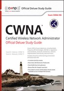
A WDS may operate by using APs with a single 802.11 radio or multiple 802.11 radios. Figure 7.2 depicts two 802.11 APs, each with a single radio. The radios in the APs not only provide access to the client stations but also communicate with each other directly as a WDS. A disadvantage to this solution is that throughput can be adversely affected because of the half-duplex nature of the medium, particularly in a single-radio scenario, where an AP cannot be communicating with a client station and another AP at the same time. The end result is a degradation of throughput.
FIGURE 7.2 Wireless distribution system, single radio
Which Distribution System Is Most Desirable?
Whenever possible, a wired network will usually be the best option for the distribution system. Because most enterprise deployments already have a wired 802.3 infrastructure in place, integrating a wireless network into an Ethernet network is the most logical solution. A wired distribution system medium does not encounter many of the problems that may affect a WDS, such as physical obstructions and radio frequency interference. A mesh backhaul network is sometimes the better option if cabling is difficult. If the occasion does arise when a wired network cannot connect access points together, a WDS might be a viable alternative. The more desirable WDS solution utilizes different frequencies and radios for client access and distribution.
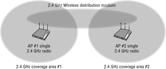
In Figure 7.3, two dual-radio access points are shown, each with radios operating at different frequencies. The 2.4 GHz radios provide access for the client stations, and the 5 GHz radios serve as the WDS link between the two access points. Throughput is not adversely affected by clients because the 2.4 GHz radio can communicate at the same time as the 5 GHz backhaul radios. Most Wi-Fi vendors now offer mesh networking capabilities that utilize the 5 GHz radios in this manner. Client connectivity could also be permitted on the 5 GHz radios; however, the throughput and performance of the 5 GHz backhaul link will be impacted by extra medium contention overhead caused by the 5 GHz client traffic. The throughput of all mesh networks is negatively impacted if there are multiple hops due to the medium contention overhead.
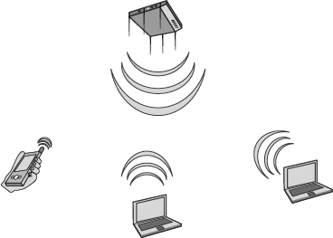
Wireless repeaters are another example of an 802.11 WDS. Repeaters are used to extend WLAN cell coverage to areas where it is not possible to provide an 802.3 Ethernet cable drop. As illustrated in Figure 7.4, a client station is associated and communicating via a repeater AP. The repeater provides coverage but is not connected to the wired backbone. When a client station sends a frame to the repeater, it is then forwarded to an access point that is connected to the wired backbone. The frame payload is converted into an 802.3 Ethernet frame and sent to a server on the backbone. The 802.11 communications between the repeater and the access point is a WDS. As shown in Figure 7.5, a frame sent within any type of WDS requires four MAC addresses: a source address, a destination address, a transmitter address, and a receiver address.
FIGURE 7.3 Wireless distribution system, dual radios
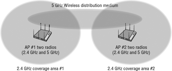
FIGURE 7.4 Repeater cell

Repeaters effectively extend the cell coverage of the original access point; therefore, both the repeater and AP must be on the same frequency channel. There must also be at least a 50 percent cell overlap between the coverage cells so that the repeater and AP can communicate with each other. Repeaters do provide coverage into areas where a cable drop is not possible. However, all frame transmissions must be sent twice, first from the client to the repeater and then from the repeater to the AP, which decreases throughput and increases latency. Because the AP cell and the repeater cell are on the same channel and exist in the same layer 1 domain, all radios must contend for the medium. Repeater environments add extra medium contention overhead, which also affects performance.
Most enterprise WLAN vendors no longer offer single radio repeaters that operate on a single frequency. Most enterprise WLAN APs have multiple radio with mesh networking capabilities that can use the 2.4 GHz radios for client access and the 5 GHz radios for backhaul, or vice versa. However, if the radio used for backhaul in a mesh environment also permits client access, it is effectively also performing as a repeater for the client traffic.
Service Set Identifier
The service set identifier (SSID) is a logical name used to identify an 802.11 wireless network. The SSID wireless network name is comparable to a Windows workgroup name. “The four 802.11 topologies utilize the SSID so that the radios can identify each other. The radios use this logical name in several different 802.11 frame exchanges.” The SSID is a configurable setting on all 802.11 radios, including access points and client stations. The SSID can be made up of as many as 32 characters and is case sensitive. Figure 7.6 shows an SSID configuration of an access point.
FIGURE 7.6 Service set identifier

Most access points have the ability to cloak an SSID and keep the network name hidden from illegitimate end users. Hiding the SSID is a very weak attempt at security that is not defined by the 802.11-2012 standard. However, it is an option many administrators still mistakenly choose to implement.
Both active and passive scanning are discussed in detail in Chapter 9, “802.11 MAC Architecture.” SSID cloaking is discussed in Chapter 13, “802.11 Network Security Architecture.”
Basic Service Set
The basic service set (BSS) is the cornerstone topology of an 802.11 network. The communicating devices that make up a BSS consist of one AP radio with one or more client stations. Client stations join the AP wireless domain and begin communicating through the AP. Stations that are members of a BSS have a layer 2 connection and are called associated. Figure 7.7 depicts a standard basic service set.
FIGURE 7.7 Basic service set
Typically the AP is connected to a distribution system medium, but that is not a requirement of a basic service set. If an AP is serving as a portal to the distribution system, client stations may communicate via the AP with network resources that reside on the DSM. It should also be noted that if client stations wish to communicate with each other, they must relay their data through the AP. In the typical BSS, client stations cannot communicate directly with each other unless they go through the AP. However, client stations could possibly belong to the BSS and communicate directly with each other if they support Wi-Fi Direct.
Basic Service Set Identifier
The 48-bit (6-octet) MAC address of an access point's radio is known as the basic service set identifier (BSSID). The simple definition of a BSSID is that it is the MAC address of the radio network interface in an access point. However, the proper definition is that the BSSID address is the layer 2 identifier of each individual BSS. Most often the BSSID is the MAC address of the radio network interface.
In the previous section, you learned that a basic service set consists of an AP with one or more stations associated with the AP. If you have two BSSs near each other, and they are both advertising the same SSID, a client station needs to identify the one BSS from the other. In order for clients to roam seamlessly, the APs must advertise the same SSID. The client stations, however, still need a unique layer 2 identifier of each AP. The BSSID provides each BSS with a unique identifier, thus the name BSSID.
Do not confuse the BSSID address with the SSID. The service set identifier (SSID) is the logical WLAN name that is user configurable, whereas the BSSID is the layer 2 MAC address of a radio provided by the hardware manufacturer. It should be noted that WLAN vendors offer the functionality to broadcast multiple SSIDs, as well as virtual BSSID capabilities; these capabilities are explained in Chapter 10.
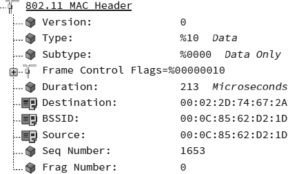
As shown in Figure 7.8, the BSSID address is found in the MAC header of most 802.11 wireless frames and is used for identification purposes of the basic service set. The BSSID address plays a role in directing 802.11 traffic within the basic service set. This address is also used as a unique layer 2 identifier of the basic service set. Furthermore, the BSSID address is needed during the roaming process.
FIGURE 7.8 Basic service set identifier
Basic Service Area
The physical area of coverage provided by an access point in a BSS is known as the basic service area (BSA). Figure 7.9 shows a typical BSA. Client stations can move throughout the coverage area and maintain communications with the AP as long as the received signal between the radios remains above received signal strength indicator (RSSI) thresholds. Client stations can also shift between concentric zones of variable data rates that exist within the BSA. The process of moving between data rates is known as dynamic rate switching and is discussed in Chapter 12, “WLAN Troubleshooting.”
FIGURE 7.9 Basic service area
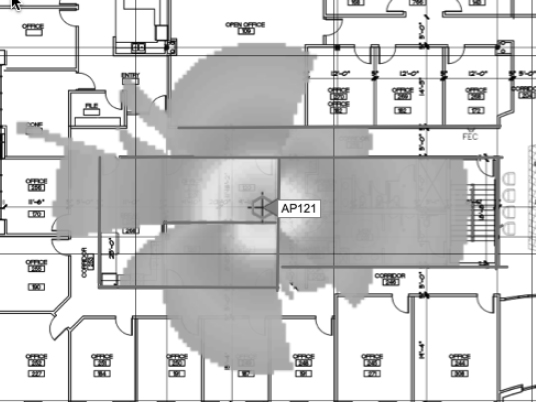
The size and shape of a BSA depends on many variables, including AP transmit power, antenna gain, and physical surroundings. Because environmental and physical surroundings often change, the BSA can often be fluid. When drawing a BSA, it is common to draw a circle around the AP to illustrate the theoretical coverage area. In reality, the real coverage area will have a disproportional shape due to the existing indoor or outdoor environment.
Extended Service Set
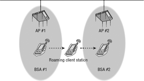
While a BSS might be considered the cornerstone 802.11 topology, an extended service set (ESS) 802.11 topology is analogous to an entire stone building. An extended service set is two or more basic service sets connected by a distribution system medium. Usually an extended service set is a collection of multiple access points and their associated client stations, all united by a single DSM.
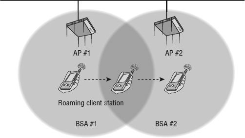
The most common example of an ESS has access points with partially overlapping coverage cells, as shown in Figure 7.10. The purpose behind an ESS with partially overlapping coverage cells is to provide seamless roaming to the client stations. Most vendors recommend cell overlap to achieve successful seamless roaming, although measuring cell overlap is not an exact science. Coverage overlap is really duplicate coverage from the perspective of a Wi-Fi client station and is discussed in greater detail in Chapter 12.
FIGURE 7.10 Extended service set, seamless roaming
Although seamless roaming is usually a key aspect of WLAN design, there is no requirement for an ESS to guarantee uninterrupted communications. For example, an ESS can utilize multiple access points with nonoverlapping coverage cells, as shown in Figure 7.11. In this scenario, a client station that leaves the basic service area of the first access point will lose connectivity. The client station will later reestablish connectivity as it moves into the coverage cell of the second access point. This method of station mobility between disjointed cells is sometimes referred to as nomadic roaming.
FIGURE 7.11 Extended service set, nomadic roaming
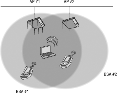
A final example of an ESS deploys multiple access points with overlapping coverage areas, as you can see in Figure 7.12. This 802.11 ESS topology is called colocation, and the intended goal is increased client capacity as opposed to roaming. Colocation is one method of providing coverage for a high density of client devices in the same area. Different strategies of high density coverage design are discussed in Chapter 12.
FIGURE 7.12 Extended service set, colocation
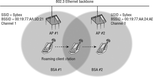
Note that all three of the previously mentioned extended service sets share a distribution system. As stated earlier in this chapter, the distribution system medium is usually an 802.3 Ethernet network; however, the DS may use another type of medium. In the majority of extended service sets, the access points all share the same SSID name. The logical network name of an ESS is often called an extended service set identifier (ESSID). The terminology of ESSID and SSID are synonymous. However, as Figure 7.13 illustrates, access points in an ESS where roaming is required must all share the same logical name (SSID) but have unique layer 2 identifiers (BSSIDs) for each unique BSS coverage cell.
FIGURE 7.13 SSID and BSSIDs within an ESS
Independent Basic Service Set
The third service set topology defined by the 802.11 standard is an independent basic service set (IBSS). The radios that make up an IBSS network consist solely of client stations (STAs), and no access point is deployed. An IBSS network that consists of just two STAs is analogous to a wired crossover cable. An IBSS can, however, have multiple client stations in one physical area communicating in an ad hoc fashion. Figure 7.14 depicts four client stations communicating with each other in a peer-to-peer fashion.
FIGURE 7.14 Independent basic service set
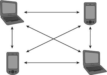
All of the stations transmit frames to each other directly and do not route their frames from one client to another. All client station frame exchanges in an IBSS are peer to peer. All stations in an IBSS must contend for the half-duplex medium, and at any given time only one STA can be transmitting.
The independent basic service set has two other names. Wi-Fi vendors often refer to an IBSS as either a peer-to-peer network or an ad hoc network.
In order for IBSS communications to succeed, all stations must be transmitting on the same frequency channel. Furthermore, this entire set of standalone wireless stations connected together as a group must share the same SSID WLAN name. Another caveat of an IBSS is that a BSSID address is created. Earlier in this chapter, we defined a BSSID as the MAC address of the radio inside an access point. So, how can an independent basic service set have a BSSID if no access point is used in the IBSS topology? The first station that starts up in an IBSS randomly generates a BSSID in the MAC address format. This randomly generated BSSID is a virtual MAC address and is used for layer 2 identification purposes within the IBSS.
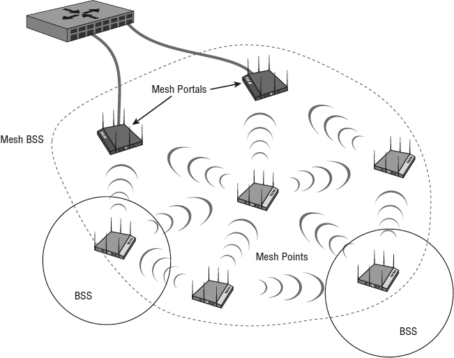
Mesh Basic Service Set
The 802.11 standard has long defined BSS, ESS, and IBSS service sets. The 802.11-2012 standard also defines a service set for an 802.11 mesh topology. When access points support mesh functions, they may be deployed where wired network access is not possible. The mesh functions are used to provide wireless distribution of network traffic, and the set of APs that provide mesh distribution form a mesh basic service set (MBSS). An MBSS requires features that are not necessary in a BSS, ESS, or IBSS because the purpose of an MBSS is different from the other topologies. As shown in Figure 7.15, one or more mesh APs will typically be connected to the wired infrastructure. This mesh AP is known as a mesh point portal, or MPP (sometimes called a mesh root or gateway). The other mesh APs that are not connected to the wired network will form wireless backhaul connections back to the mesh portals to reach the wired network. Mesh APs that are not connected to a wired infrastructure are known as mesh points, or MPs. Client stations that are associated to the mesh points have their traffic forwarded through the wireless backhaul. As stated earlier, an MBSS makes use of a wireless distribution system medium for backhaul communications. Usually the MBSS uses the 5 GHz radios for backhaul communications.
FIGURE 7.15 Mesh basic service set
The mesh nodes in an MBSS function much like routers in a network, because their goal is to discover neighbor mesh stations, identify possible and best connections back to the portal, form neighbor links, and share link information. Keep in mind that 802.11 frame exchanges are a layer 2 operation; therefore, mesh routing of 802.11 traffic is based on MAC addresses and not IP addresses. A hybrid wireless mesh protocol (HWMP) is defined as the default path selection protocol for an MBSS. HWMP is both proactive and reactive and is effectively a dynamic layer 2 routing protocol. Note that WLAN vendors have offered mesh capabilities for many years using proprietary layer 2 mesh protocols. Most vendors continue to use their own dynamic layer 2 mesh mechanisms utilizing metrics such as RSSI, SNR, client load, and hop counts to determine the best path for the backhaul traffic.
QoS Basic Service Set
Quality of service (QoS) mechanisms can be implemented within all of the 802.11 service sets. The QoS enhancements are available to QoS STAs associated with a QoS access point in a QoS BSS. QoS stations may also belong to the same QoS IBSS. Older radios that do not support quality of service mechanisms are known as non-QoS STAs and non-QoS APs. 802.11 QoS mechanisms are discussed in greater detail in Chapter 8, “802.11 Medium Access.”
![]() Real World Scenario
Real World Scenario
Vendor Considerations When Deploying and Integrating 802.11 WLAN Infrastructure
When deploying 802.11 infrastructure, the recommended practice is to purchase the equipment from one vendor. A bridge from vendor A is not likely to work with a bridge from vendor B. A mesh point from vendor A most likely will not communicate with a mesh portal from vendor B. Another example of likely interoperability is fast secure roaming. Client stations will probably not be able to roam effectively when using a mix of different WLAN vender access points.
The main purpose of an 802.11 AP is to act as a portal to a wired network infrastructure. Although 802.11 technology operates at layers 1 and 2, there are always higher layer design considerations. All WLAN vendors have different strategies on how to integrate into a preexisting wired network infrastructure. For that reason, the normal best practice is to stick with one enterprise WLAN vendor when deploying and integrating an 802.11 infrastructure.
802.11 Configuration Modes
While the 802.11-2012 standard defines all radios as stations (STAs), an access point (AP) radio and a client station radio can each be configured in a number of ways. The default configuration of an AP radio is to allow it to operate inside a basic service set (BSS) as a portal device to a wired network infrastructure. However, an AP can be configured to function in other operational modes. Client stations can be configured to participate in either a BSS or an IBSS 802.11 service set.
Access Point Modes
The default configuration of some WLAN vendor access points is known as root mode. The main purpose of an AP is to serve as a portal to a distribution system. The normal default setting of an AP is root mode, which allows the AP to transfer data back and forth between the DS and the 802.11 wireless medium. Not all vendors have the same names for this mode of operation. For example, many Wi-Fi vendors use the term AP mode or access mode instead of root mode.
The default root configuration of an AP radio allows it to operate as part of a BSS. There are, however, other operational modes in which an AP may be configured:
Bridge Mode The AP radio is converted into a wireless bridge. This typically adds extra MAC-layer intelligence to the device and gives the AP the capability to learn and maintain tables about MAC addresses from the wired side of the network.
Workgroup Bridge Mode The AP radio is transformed into a workgroup bridge which provides wireless backhaul for connected 802.3 wired clients.
Repeater Mode The AP radio performs as a repeater AP which extends the coverage area of a portal AP on the same channel.
Mesh Mode The AP radio operates as a wireless backhaul radio for a mesh environment. Depending on the vendor, the backhaul radio may also allow for client access.
Scanner Mode The AP radio is converted into a sensor radio, allowing the AP to integrate into a wireless intrusion detection system (WIDS) architecture. An AP in scanner mode is in a continuous listening state while hopping between multiple channels. Scanner mode is also often referred to as monitor mode.
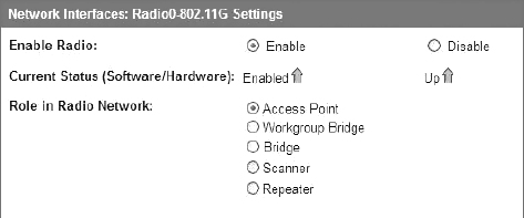
The 802.11 standard does not define these AP operational modes; therefore, every WLAN vendor will have different capabilities. These modes of operation are “radio configuration modes” and may be able to be applied to a 2.4 GHz radio in an AP, a 5 GHz radio in an AP, or both radios within an AP. You can see an AP's various configurable modes in Figure 7.16.
FIGURE 7.16 Access point configuration modes
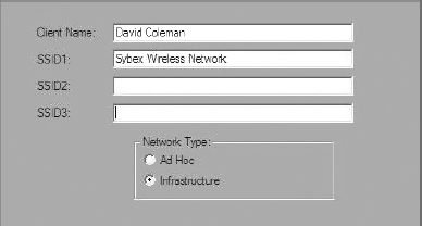
Client Station Modes
A client station may operate in one of two states, as shown in Figure 7.17. The default mode for an 802.11 client radio is typically infrastructure mode. When running in Infrastructure mode, the client station will allow communication via an access point. Infrastructure mode allows for a client station to participate in a basic service set or an extended service set. Clients that are configured in this mode may communicate, via the AP, with other wireless client stations within a BSS.
FIGURE 7.17 Client station configuration modes
Clients may also communicate through the AP with other networking devices that exist on the distribution system, such as servers or wired desktops.
The second client station mode is called Ad Hoc mode. Other vendors may refer to this as Peer-to-Peer mode. 802.11 client stations set to Ad Hoc mode participate in an IBSS topology and do not communicate via an access point. All station transmissions and frame exchanges are peer to peer.
Summary
This chapter covered the major types of generic wireless topologies as well as the topologies specific to 802.11 wireless networking:
- The four wireless architectures that can be used by many different wireless technologies
- The four service sets as defined by the 802.11-2012 standard, and the various aspects and purposes defined for each service set
- Operational configuration modes of both access points and client stations
As a wireless network administrator, you should have a full understanding of the defined 802.11 service sets and how they operate. Administrators typically oversee the design and management of an 802.11 ESS, but there is a good chance that they will also deploy 802.11 radios using a variety of operational modes.
Exam Essentials
Know the four major types of wireless topologies. Understand the differences between a WWAN, WLAN, WPAN, and WMAN.
Explain the four 802.11 service sets. Be able to fully expound on all the components, purposes, and differences of a basic service set, an extended service set, an independent basic service set, and a mesh basic service set. Understand how the 802.11 radios interact with each other in each service set.
Identify the various ways in which an 802.11 radio can be used. Understand that the 802.11 standard expects a radio to be used either as a client station or inside an access point. Also understand that an 802.11 radio can be used for other purposes, such as bridging, repeating, and so on.
Explain the purpose of the distribution system. Know that the DS consists of two pieces: distribution system services (DSS) and the distribution system medium (DSM). Understand that the medium used by the DS can be any type of medium. Explain the functions of a wireless distribution system (WDS).
Define SSID, BSSID, and ESSID. Be able to explain the differences or similarities of all three of these addresses and the function of each.
Describe the various ways in which an ESS can be implemented and the purpose behind each design. Explain the three ways in which the coverage cells of the ESS access points can be designed and the purpose behind each design.
Explain access point and client station configuration modes. Remember all the configuration modes of both an AP and a client station.
Review Questions
- An 802.11 wireless network name is known as which type of address? (Choose all that apply.)
- BSSID
- MAC address
- IP address
- SSID
- Extended service set identifier
- Which two 802.11 topologies require the use of an access point?
- WPAN
- IBSS
- Basic service set
- Ad hoc
- ESS
- The 802.11 standard defines which medium to be used in a distribution system (DS)?
- 802.3 Ethernet
- 802.15
- 802.5 token ring
- Star-bus topology
- None of the above
- Which option is a wireless computer topology used for communication of computer devices within close proximity of a person?
- WWAN
- Bluetooth
- ZigBee
- WPAN
- WMAN
- Which 802.11 service set may allow for client roaming?
- ESS
- Basic service set
- IBSS
- Spread spectrum service set
- What factors might affect the size of a BSA coverage area of an access point? (Choose all that apply.)
- Antenna gain
- CSMA/CA
- Transmission power
- Indoor/outdoor surroundings
- Distribution system
- What is the default configuration mode that allows an AP radio to operate in a basic service set?
- Scanner
- Repeater
- Root
- Access
- Nonroot
- Which terms describe an 802.11 topology involving STAs but no access points? (Choose all that apply.)
- BSS
- Ad hoc
- DSSS
- Infrastructure
- IBSS
- Peer-to-peer
- STAs operating in Infrastructure mode may communicate in which of the following scenarios? (Choose all that apply.)
- 802.11 frame exchanges with other STAs via an AP
- 802.11 frame exchanges with an AP in scanner mode
- 802.11 frame peer-to-peer exchanges directly with other STAs
- Frame exchanges with network devices on the DSM
- All of the above
- Which of these are included in the four topologies defined by the 802.11-2012 standard? (Choose all that apply.)
- DSSS
- ESS
- BSS
- IBSS
- FHSS
- Which wireless topology provides citywide wireless coverage?
- WMAN
- WLAN
- WPAN
- WAN
- WWAN
- At which layer of the OSI model will a BSSID address be used?
- Physical
- Network
- Session
- Data-Link
- Application
- The basic service set identifier address can be found in which topologies? (Choose all that apply.)
- FHSS
- IBSS
- ESS
- HR-DSSS
- BSS
- Which 802.11 service set defines mechanisms for mesh networking?
- BSS
- DSSS
- ESS
- MBSS
- IBSS
- What method of dialog communications is used within an 802.11 WLAN?
- Simplex communications
- Half-duplex communications
- Full-duplex communications
- Dual-duplex communications
- What are some operational modes in which an AP radio may be configured? (Choose all that apply.)
- A network consisting of clients and two or more access points with the same SSID connected by an 802.3 Ethernet backbone is one example of which 802.11 topology? (Choose all that apply.)
- ESS
- Basic service set
- Extended service set
- IBSS
- Ethernet service set
- What term best describes two access points communicating with each other wirelessly while also allowing clients to communicate through the access points?
- WDS
- DS
- DSS
- DSSS
- DSM
- What components make up a distribution system? (Choose all that apply.)
- HR-DSSS
- Distribution system services
- DSM
- DSSS
- Intrusion detection system
- What type of wireless topology is defined by the 802.11 standard?
- WAN
- WLAN
- WWAN
- WMAN
- WPAN