
IN THIS CHAPTER, YOU WILL LEARN ABOUT THE FOLLOWING:
- 802.11ac-2013 amendment
- 5 GHz only
- 20, 40, 80, and 160 MHz channels
- 256-QAM modulation
- Modulation and coding schemes
- Single-user MIMO
- 802.11ac data rates
- VHT MAC
- A-MPDU
- RTS/CTS
- Beamforming
- Explicit beamforming
- Multiuser MIMO
- Multiuser beamforming
- Quality of service
- Infrastructure requirements
- Ethernet
- Power
- 802.11ac in a SOHO or home
- Device radios
- Data flow/usage
- Spatial streams
- Wider 802.11ac channels
- MU-MIMO
- Wi-Fi Alliance certification
 In 2009, the IEEE ratified the 802.11n amendment and High Throughput (HT). The introduction of 802.11n was a milestone and game changer for Wi-Fi networks. The increased data rates offered by 802.11n provided organizations with the technology necessary to scale down or even replace their end-user wired network with wireless. Although the faster data rates of 802.11n allowed companies to unplug their users, the demand for faster networks is continuous. In response to end users' thirst for faster networks, 802.11ac was developed and was ratified in December 2013.
Compared with the other 802.11 PHYs that preceded it, the introduction of 802.11n was revolutionary. It did not just update and enhance the existing 802.11 standard. With technologies such as MIMO, spatial streams, bonded channels, aggregate MSDU, and aggregate MPDU, 802.11n required us to sit down and spend time learning about how Wi-Fi had changed. So four years later, once again a new PHY has been introduced—the latest 802.11 PHY, 802.11ac. The goal of this chapter is to introduce you to the technologies covered by this amendment.
The 802.11ac-2013 amendment defines a new operation known as Very High Throughput (VHT), which provides PHY and MAC enhancements and allows data rates potentially as high as 6.933 Gbps. Although the amendment specifies data rates up to 6.933 Gbps, 802.11ac products will be implemented in multiple phases, with two key initial phases. The first phase supports rates up to 1.3 Gbps, and the second phase is expected to support rates up to 3.5 Gbps.
With 802.11ac, many of the technologies that were introduced with 802.11n are being enhanced to achieve faster data rates. Increased channel bandwidth, more radio chains and spatial streams, and an enhanced modulation and coding scheme are the three technologies that help the first deployments of 802.11ac provide data rates of up to 1.3 Gbps. These enhancements are more evolutionary than revolutionary and enhance and improve technologies that we are already familiar with.
The second-phase rollout of 802.11ac will further enhance these technologies by increasing the number of radio chains and spatial streams to achieve even higher data rates. In addition to achieving faster speeds, 802.11ac products will introduce a technology that will be revolutionary, drastically changing how Wi-Fi behaves. This second-phase rollout will change Wi-Fi from a single transmission at a time technology to a multiuser technology. This change is comparable to the changes that occurred when Ethernet networks transitioned from repeater-based, single collision domain networks to switch-based broadcast domain environments. This revolutionary new technology is known as multiuser MIMO, or MU-MIMO. In order to make MU-MIMO successful, 802.11ac uses beamforming, technology that was initially introduced with 802.11n. This chapter will introduce you to 802.11ac and how it achieves its faster data rates and provide information about how MU-MIMO works.
802.11ac-2013 Amendment
The 802.11ac-2013 amendment was ratified on December 11, 2013. The amendment is officially known as “Amendment 4: Enhancements for Very High Throughput for Operation in Bands below 6 GHz.” Although the amendment title states bands below 6 GHz, 802.11ac technology does not operate in the 2.4 GHz ISM band, only the 5 GHz U-NII bands. 802.11ac introduces Very High Throughput (VHT) technology with maximum transmission speed of 6.933 Gbps.
Table 19.1 provides a summary of the differences between 802.11n and 802.11ac. This chapter will discuss all of the new features and capabilities of 802.11ac, along with highlighting the similarities and the differences between the two technologies. Remember that 802.11ac will be implemented in multiple phases, so some of the features or capabilities listed in the table may not exist yet in live product.
TABLE 19.1 Comparison of 802.11n and 802.11ac

5 GHz Only
Over the years, it has become common practice for enterprises to install dual-band access points throughout their networks. This practice has allowed organizations to migrate to the 5 GHz band while still providing support for older 802.11b/g clients and other single-radio 2.4 GHz clients. Many organizations also use the dual-band APs to provide guest access solely on the slower and more limited 2.4 GHz band. Employee access is provided on the 2.4 GHz band for older devices and on the less congested 5 GHz band for better performance.
With the introduction of 40 MHz channels in 802.11n and the limit of 3 nonoverlapping channels in the 2.4 GHz band, enterprises cannot effectively implement 40 MHz channels with their 2.4 GHz radios. Therefore, in order to benefit from the faster data rates of 802.11n, companies have migrated to 5 GHz radios. However, support for 2.4 GHz radios in older devices is still needed. This is accomplished with dual-radio access points.
802.11ac expands channel widths even further than 802.11n, with channel widths of 80 MHz and 160 MHz. Due to the limited frequency space in the 2.4 GHz band, 802.11ac is designed to operate only in the 5 GHz band where much more frequency space is available.
Dual-Band APs and 802.11ac
Dual-band APs will continue to be manufactured and installed. The 2.4 GHz radios will support 802.11b/g/n, although they will still be limited by only three available channels. The 5 GHz radios will support 802.11ac and be backward compatible with 802.11a and 5 GHz 802.11n and will support channels that are 20, 40, 80, and ultimately 160 MHz wide.
20, 40, 80, and 160 MHz Channels
802.11ac channels are a further evolution of the enhancements that were introduced with the 802.11n amendment. When Orthogonal Frequency Division Multiplexing (OFDM) was introduced with 802.11a, the channels were 20 MHz wide. The 20 MHz channels consisted of 64 subcarriers, each one 312.5 KHz wide, as pictured in Figure 19.1. Of these, 52 subcarriers are used by 802.11a OFDM, 48 to transmit data and 4 as pilot carriers.
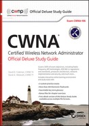
802.11n introduced an enhanced 20 MHz channel and increased the number of subcarriers that could be used to 56, as pictured in Figure 19.2. Of these 56 subcarriers, 52 are used to transmit data and the other 4 are used as pilot carriers.
802.11n also introduced a 40 MHz channel, which combined two 20 MHz channels, as pictured in Figure 19.3. The 40 MHz channel consists of 128 subcarriers; 108 transmit data, 6 act as pilot carriers, and the other 14 are unused.
FIGURE 19.1 20 MHz non-HT (802.11a) channel
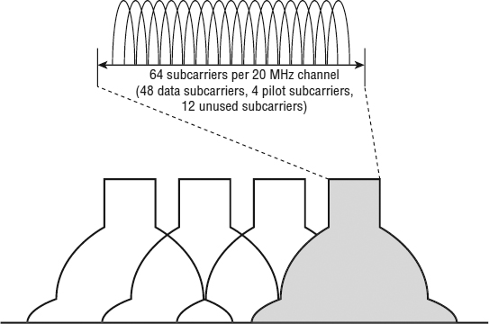
FIGURE 19.2 20 MHz HT (802.11n) channel

When two 20 MHz HT channels are bonded together, some of the formerly unused subcarriers at the bottom of the higher channel and at the top end of the lower channel are able to be used to transmit data. That is why the number of subcarriers is slightly more than two times the 56 subcarriers in a 20 MHz channel.
Each bonded channel consists of a primary and secondary 20 MHz channel. The channels must be adjacent. A positive or negative offset indicates whether the secondary channel is the channel above or the channel below the primary channel. This is pictured in Figure 19.4.
FIGURE 19.3 40 MHz HT (802.11n) channel
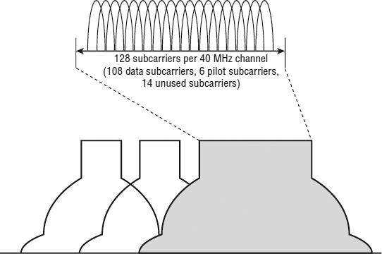
FIGURE 19.4 Channel bonding
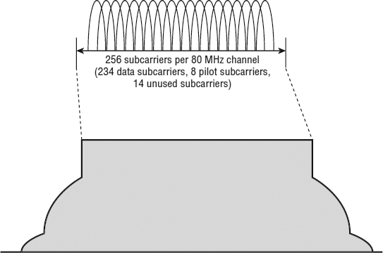
802.11ac introduced two new channel widths: 80 MHz and 160 MHz. Just as a 40 MHz channel is created by combining two 20 MHz channels, an 80 MHz channel combines two 40 MHz channels. The two 40 MHz channels that make up the 80 MHz channel must be adjacent. (An 80 MHz channel is pictured in Figure 19.5.) Some of the formerly unused subcarriers between the adjacent channels are now able to be used. Therefore, the number of 80 MHz subcarriers used is slightly more than two times the 114 subcarriers in a 40 MHz channel. The new 80 MHz channel consists of 256 subcarriers, of which 234 are used to transmit data, 8 are used as pilot carriers, and the remaining 14 are unused.
FIGURE 19.5 80 MHz VHT (802.11ac) channel
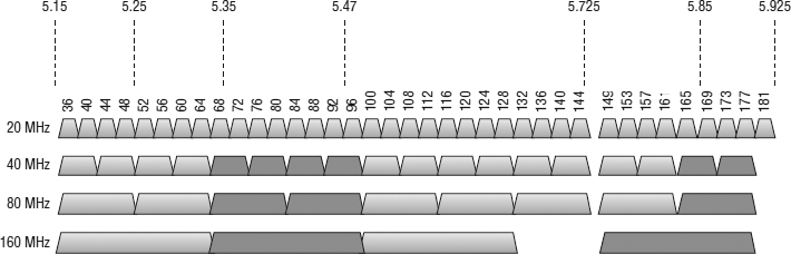
The second channel width that was introduced with 802.11ac is a 160 MHz channel. As you might deduce, the 160 MHz channel is made up of two 80 MHz channels; however, the two 80 MHz channels do not have to be adjacent. If the channels are adjacent, then it is referred to as a 160 MHz channel. If they are not adjacent, then it is referred to as an 80+80 MHz channel. Since these channels can be adjacent or separated, they are treated as two individual 80 MHz channels, and you do not gain any unused subcarriers between the channels. Therefore, a 160 MHz channel is simply two 80 MHz channels and consists of 512 subcarriers, with 468 used to transmit data, 16 used as pilot carriers, and the remaining 28 are unused. Now that you have seen all of the channel widths individually, Figure 19.6 displays them across the current and proposed U-NII bands. This figure includes the channels defined in the FCC “Notice of Proposed Rulemaking,” document #13-22. We realize that different regulatory domains may restrict or allow different frequency ranges, and there is even a chance that some of the new U-NII-2B channels may not get approved by the FCC. Taking both of these variables into consideration, we still believe it is worthwhile to see the 20 MHz, 40 MHz, 80 MHz, and 160 MHz channel options in the 5 GHz U-NII bands.
With 802.11n, an access point (AP) could be configured to use either 20 MHz channels or 40 MHz channels. When an AP was configured for a 40 MHz channel, it could not transmit until both the primary and secondary 20 MHz channels were available. A neighboring 20 MHz AP could be transmitting on either of the 20 MHz channels and force the 40 MHz AP to wait before it could transmit, reducing the performance capabilities of the 802.11n AP.
With 802.11ac, a new feature has been added that allows the AP to choose the channel width on a per-frame basis. This feature is known as dynamic bandwidth operation. As an example, when an 802.11ac AP, operating at 80 MHz on channels 36, 40, 44, and 48, wants to transmit, it must first check to see if all four channels are available.
If one of the channels, such as 36, is currently being using by another AP, instead of waiting for all four channels to be available to perform an 80 MHz transmission, the AP can transmit using a 40 MHz transmission on channels 44 and 48. This capability allows 802.11ac devices to adapt to the environment while transmitting on the widest available channel.
FIGURE 19.6 20, 40, 80, and 160 MHz channels
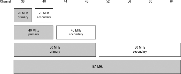
The ability to switch bandwidth dynamically adds complexity to the channel selection process for the person, or more likely the wireless networking software, that is configuring the AP. Prior to 802.11ac, channel selection simply meant choosing a single channel for the radio. With an 802.11ac radio, channel selection for a single radio can require the selection of up to four channel groupings. In the example shown in Figure 19.7, channels 36 through 64 are chosen for the 160 MHz channel. From this grouping of channels, 36 through 48 are chosen as the primary 80 MHz channel. Then channels 36 through 40 are chosen as the primary 40 MHz channel, and finally, channel 36 is chosen as the primary 20 MHz channel.
FIGURE 19.7 Single AP 160 MHz channel plan
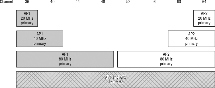
Choosing four channel groupings for an AP may not seem that difficult, but it becomes much more difficult and important when choosing channels for multiple APs. Figure 19.8 illustrates the channel plans for two APs that are using the same channels, 36 through 64 for 160 MHz transmissions. In this example, either AP can transmit at 160 MHz, providing that channels 36 through 64 are not currently being used by the other AP. Since the primary channels of these APs are different, both could transmit at the same time using 80 MHz wide transmissions. AP1 could transmit on its primary 80 MHz channel, channels 36 through 48, while AP2 transmitted on its primary 80 MHz channel, channels 52 through 64. If a third and fourth AP were configured for the same 160 MHz channels, they would not be able to choose an 80 MHz channel range that was not already chosen by AP1 or AP2; however, APs 3 and 4 would be able to choose 40 MHz primary channels that are not already used, either channels 44 and 48 or channels 52 and 56. Now you understand how primary channel selection becomes more complex as more APs join the network.
FIGURE 19.8 Two APs, 160 MHz channel plan
Just as more lanes on a highway allow more cars to travel down a road, wider channels allow more data to be transmitted. In its initial phase, 802.11ac supports channels that are 20 MHz, 40 MHz, and 80 MHz wide. The wider 40 MHz and 80 MHz channels are a key component to delivering the faster transmission speeds offered by 802.11ac. The second phase of 802.11ac will provide support for the maximum channel width of 160 MHz. The extreme size of the 160 MHz channels limits the number of available 160 MHz channels. Therefore, 160 MHz channels will most likely be deployed less often and used to address specific low-density, high-throughput requirements. Remember that in order to transmit using a 160 MHz channel, the access point must do a clear channel assessment across the entire 160 MHz frequency range, and all eight 20 MHz channels must be available before the transmission can begin. Fortunately, as we explained in this section, if the 160 MHz channel is not available, 802.11ac allows the AP to step down and transmit on a narrower channel if that primary channel is available.
256-QAM Modulation
In Chapter 1, “Overview of Wireless Standards, Organizations, and Fundamentals,” we explained how waves are manipulated, or modulated, in order to carry data. The chapter described how amplitude, frequency, or phase could be varied to represent a single bit of data, or even multiple bits of data. Over the years, newer and faster modulation methods have been incorporated into 802.11 physical layer (PHY) technologies. With the introduction of each new and faster PHY, a newer modulation method, capable of encoding more bits, was also introduced and thus increased the effective speed and performance of the network. It is important to remember that even as new transmission and modulation methods are introduced, the older and slower methods are still supported and used.
As a client moves away from an access point and the signal level decreases, dynamic rate switching causes the client to shift to a slower data rate to maintain a connection. Even though we tend to highlight the latest and greatest technologies that are introduced with the most recent standard or amendment, the older and slower technologies are still key and necessary components of any infrastructure. This section describes 256-QAM, which was introduced with the 802.11ac amendment. (QAM is the acronym for quadrature amplitude modulation and is pronounced “kwam,” which rhymes with “Tom.”) The following is a list of modulation methods that are used with 802.11 networks:
DBPSK—Differential binary phase shift keying
DQPSK—Differential quadrature phase shift keying
BPSK—Binary phase shift keying
QPSK—Quadrature phase shift keying
16-QAM—16 quadrature amplitude modulation
64-QAM—64 quadrature amplitude modulation
256-QAM—256 quadrature amplitude modulation
256-QAM is an evolutionary upgrade that was introduced with 802.11ac. The 802.11a amendment introduced 64-QAM modulation. 64-QAM identifies 64 unique values. 64-QAM essentially performs a phase shift that can differentiate eight different levels and also performs an amplitude shift, which can also differentiate eight different levels. Combine the two of them and the system has the ability to identify the 64 unique values. Having 64 distinct values provide the ability for each value to represent 6 bits (26 = 64). QAM is often represented by symbols displayed in a constellation chart, as shown in Figure 19.9. Each dot represents a unique symbol—a different grouping of 6 bits.
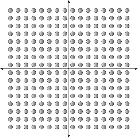
With 802.11ac, a new modulation method was introduced, 256-QAM. 256-QAM identifies 256 unique values, using 16 different levels of phase shift and 16 different levels of amplitude shift. Because there are 256 distinct values, each value is able to represent 8 bits. (28 = 256). The constellation chart for 256-QAM is displayed in Figure 19.10.
FIGURE 19.9 64-QAM constellation chart
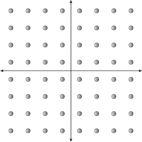
Now that we have provided a basic explanation of 64-QAM and 256-QAM, we need to delve a little deeper so that you understand what is happening and how the two differ. When a 64-QAM radio transmits data, it modifies the amplitude and phase of the wave and then transmits it. The receiving radio must then take the signal and identify the amplitude and phase modifications that were made to identify which of the 64 symbols was transmitted. This is not always easy because noise and interference can make it difficult to identify the values of the transmitted signal.
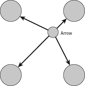
As an analogy, consider an archer shooting arrows at a target. Suppose that the target is a 2-meter-square board with evenly spaced 1-inch dots in rows and columns of eight that stands on the roof of a building, which we will call the target roof. Ten meters away from the target roof is another roof where an Olympic archer is standing. We will call this the shooting roof. In perfect conditions, our Olympic archer never misses. However, the space between these two buildings is unpredictably windy, not only from side to side, but also with updrafts and downdrafts. From the shooting roof, we ask the archer to shoot an arrow at a specific dot on the target. Since the winds are so unpredictable, the archer does not make any adjustments or corrections, only aims for the chosen dot and hopes that the winds do not push the arrow too far off target.
When the arrow hits the target, a person on the target roof looks at the location of the arrow and, using a ruler, measures the distance of the arrow from the nearest dots and attempts to identify which dot the archer was shooting at. As an example, Figure 9.11 shows four dots and the location where the arrow hit. In this figure, the person would identify the upper-right dot as the one that the archer was aiming for. At this short distance, unless the wind was incredibly strong, the archer should be able to accurately shoot the arrow on or near the correct dot, and the person at the target should be able to properly identify which dot the archer was aiming for.
FIGURE 19.10 256-QAM constellation chart
If we incrementally move the archer farther away from the target, the wind will interfere more with the flight of the arrow, possibly making it drift farther from the dot that the archer was aiming for. The farther away from the target, the less successful the archer will be. 64-QAM behaves similarly. The transmitting radio modulates the signal and transmits it. The amplitude and phase adjustments are exact and a perfectly modulated signal is generated by the radio. Noise, interference, and signal attenuation alter the signal so that when it is received it has been modified. The receiver takes the signal and maps it on the constellation diagram and calculates the error vector to identify the constellation point, which equates to the data that was transmitted.
So, now that you have a general idea of how 64-QAM behaves, how does it relate to 256-QAM? That is fairly straightforward. In our archer analogy, instead of having 64 dots on the target, we use the same size target but place 256 dots on it. This means that there is less room for error, and the effect of the wind on the arrow is much more critical. In the same way, 256-QAM is more sensitive to noise and interference. Because of this, 802.11ac receiver performance requires about 5 dB of additional gain as compared to 64-QAM.
256-QAM is used for the highest modulation coding sets. To achieve these higher data rates, higher signal-to-noise ratios are needed. This also means that the clients need to be close to the AP in order to achieve these data rates. Since a 256-QAM signal can transmit 8 bits per subcarrier compared with the 6 bits that were transmitted with 64-QAM, a speed increase of 33 percent is achieved solely by deploying this feature.
As mentioned earlier, 802.11ac is only supported in the 5 GHz bands, leaving 802.11n as the fastest technology supported in 2.4 GHz. The fastest modulation officially supported by the 802.11n amendment is 64-QAM. With 802.11ac dual-band radios, even though 256-QAM is not part of the 802.11n standard, the technology is already integrated into the 802.11ac radio chipsets. Therefore, many vendors are enabling this technology on the 2.4 GHz radios, unofficially increasing the fastest 2.4 GHz data rates by about 33 percent.
 Some of the chipset vendors have introduced this capability, sometimes known as Turbo-QAM when implemented on the 2.4 GHz radios. Turbo-QAM is a Broadcom marketing term for 256-QAM deployed on a 2.4 GHz radio and does not imply the implementation of any other 802.11ac technologies in the 2.4 GHz band.
Modulation and Coding Schemes
802.11n (HT) defined 77 different modulation and coding schemes (MCSs). HT radios defined MCSs based on numerous factors, including modulation, coding method, the number of spatial streams, channel size, and guard interval. 802.11n also defined MCSs that allowed unequal modulation, which is the use of different modulation and coding schemes at the same time on different spatial streams. 802.11ac simplified this by defining only 10 MCS options, as shown in Table 19.2.
TABLE 19.2 VHT MCS, modulation, code rate, and data rate
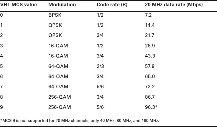
The first eight modulation and coding schemes are mandatory; however, most vendors will support the last two, which provide 256-QAM modulation. The code rate (R) column shows the error-correcting code used by each MCS. Error-correcting codes add redundant information to assist with error recovery. The code rate is represented by a fraction. The first number (numerator) represents the quantity of user data bits, relative to the number of bits on the channel (denominator)—the higher the code rate, the more data transmitted and the less redundancy provided.
The last column represents the maximum achievable data rate for each MCS. The data rate is based on a 20 MHz wide channel, a single spatial stream, and a short guard interval (400 ns).
Unlike previous 802.11 PHYs, 802.11ac does not provide the ability to individually disable data rates. VHT-MCS Map fields do support the selection and use of MCS 0-7, MCS 0-8, or MCS 0-9.
Single-User MIMO
With the introduction of 802.11ac, a new form of MIMO was introduced: multiuser MIMO (MU-MIMO). MU-MIMO is a revolutionary technology that will be discussed in depth later in this chapter. To distinguish the MIMO technology that was introduced with 802.11n from MU-MIMO, we will refer to it as single-user MIMO (SU-MIMO).
The 802.11n amendment allows up to four spatial streams of data to be transmitted. Although four spatial streams are supported by the 802.11n amendment, most 802.11n APs support only three. The 802.11ac amendment doubles the total number of supported spatial streams to eight. This enhancement alone doubles the potential transmission speed, relative to its predecessor, 802.11n.
Although the amendment specifies a maximum of eight spatial streams, it is unlikely that APs that support eight streams will be manufactured any time soon. However, the second wave of 802.11ac access point chipsets that are expected to support MU-MIMO will most likely be 4×4:4 radios. It is also likely that 4×4:4 radios will emerge in laptop radios; however, 802.11ac radios in tablets and smartphones will most likely remain 1×1:1 or 2×2:2 due to battery life and the increased power required to implement multiple-spatial-stream radios. Each spatial stream requires its own radio chain, along with an antenna for the radio chain. Additionally, in order for a radio to support more than one spatial stream, digital signal processors are needed to handle the computations needed to combine the multiple spatial streams into a single transmission. With each additional spatial stream, additional computations are needed, and in order to handle the additional computations and processors, there are additional power demands that can affect battery life or PoE requirements.
The 802.11n amendment supported a technology known as unequal modulation, which allowed an AP to transmit the spatial streams using different modulation and coding schemes. This was eliminated in 802.11ac to simplify the supported data rates. So if an AP is using three spatial streams, the throughput will be three times the throughput of the individual stream. As an example, if the AP chose MCS 8 (described earlier in Table 19.2), then the throughput would be 86.7 Mbps times 3, which equals 260.1 Mbps.
As we mentioned, the use of multiple spatial streams requires more power. Unfortunately, more and more of the devices that connect to wireless networks are battery powered. As such, many of these devices only implement a single-spatial-stream radio, because single-spatial-stream transmissions do not require a digital signal processor. The performance of these single-spatial-stream devices will, however, benefit from the wider transmission channels. Although the wider channel requires more energy, the faster data rates reduce the transmission time. With the first phase of 802.11ac devices, if any device is transmitting, it is the sole user of the channel. Thus, a single-spatial-stream portable device will tie up the channel and all of the spatial streams, even though it is only using one of them. Later in this chapter you will learn about multiuser MIMO and how wireless communications will be drastically changed.
802.11ac Data Rates
So far in this chapter we have discussed key pieces of 802.11ac as they relate to increases in performance and data rates. Like 802.11n, it is not one specific enhancement that provides 802.11ac with its faster data rates but a combination of enhancements. This section will review the key components involved with increased performance and explain how 802.11ac can boast data rates of up to 6.933 Gbps.
The first enhancement toward the increased data rates of 802.11ac is 256-QAM. This is incorporated into MCS 8 and MCS 9. Table 19.3 shows the maximum data rate for each MCS operating on a single spatial stream and a 20 MHz wide channel and using a 400 ns short guard interval. Due to technical and practical reasons, some MCS values are not supported with certain channel width and spatial stream combinations. There are 10 such instances. MCS 6 is not supported for an 80 MHz channel when using three or seven spatial streams. MCS 9 has the most exceptions. It will not work with a 20 MHz channel when using one, two, four, five, seven, or eight spatial streams. It will not work with an 80 MHz channel with six spatial streams, and it will not work with a 160 MHz channel with three spatial streams.
TABLE 19.3 802.11ac data rate factors
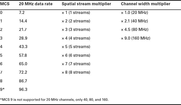
As you can see in Table 19.3, there are 10 MCSs, which can be deployed on up to eight spatial streams, using up to four channel widths. Remember that there are 10 combinations that are not available due to technical reasons. Taking all of this into consideration, we can do the math to calculate the number of different available data rates: (10 × 8 × 4) − 10 = 310.
The next enhancement to factor into the increase in data rates is the increase in the number of spatial streams. Each spatial stream is a transmission that is capable of the data rate provided by the MCS that it is using to transmit. Calculating the data rate increase is simply a matter of multiplying the 20 MHz data rate by the number of spatial streams, as shown in the spatial stream multiplier column of Table 19.3.
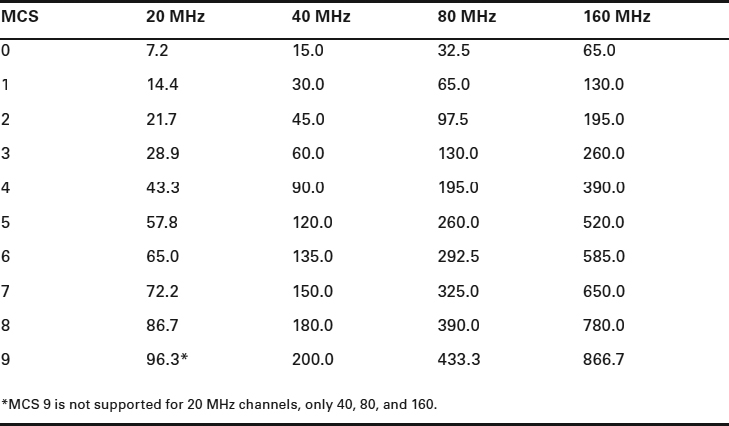
The last enhancement to factor into the increase in data rates is the channel width. Earlier in this chapter we explained that when combining channels, not only did we increase the throughput due to doubling of the channel, but we also gained a little more channel space from the area between the two bonded channels. Therefore, the increase for a 40 MHz channel is 2.1 times, and the increase for an 80 MHz channel is 4.5 times. Since a 160 MHz channel consists of two 80 MHz channels, either side by side or separated, there is no additional gain. The multiplier for a 160 MHz channel is simply twice that of the 80 MHz channel, 9 times. Table 19.4 shows the maximum data rate across each of the channel widths for each MCS when operating on a single spatial stream and using a 400 ns short guard interval.
TABLE 19.4 Maximum data rates (Mbps)
An Operating Mode Notification element of an Operating Mode Notification frame is used by a transmitting station to notify other stations that it is changing (other frames notify the stations of the initial settings) its operating channel width, changing the maximum number of spatial streams that it can receive, or both. The notification provides information about the number of spatial streams (up to and including the specified number) being employed and the bandwidth (up to and including the specified channel width) at which the station can receive frames.
VHT MAC
When 802.11 networks transitioned from 802.11b to 802.11g, one of the problems that had to be dealt with was backward compatibility and coexistence. Since 802.11ac does not operate on the 2.4 GHz bands, it does not have to worry about 802.11b, 802.11g, or 2.4 GHz 802.11n radios. That still leaves it to deal with coexisting on the 5 GHz band with 802.11a and 802.11n radios. Fortunately, all three PHYs use the OFDM preamble. When a transmission is performed using any of these PHYs, the other radios hear the preamble and can calculate how long to wait before they can transmit.
A-MPDU
All 802.11ac frames are transmitted using the Aggregate MAC Protocol Data Unit (A-MPDU) frame format, even if only a single frame is being transmitted. A-MPDU reduces some of the overhead involved with transmitting multiple frames. Aggregation also shifts some of the frame information from the Physical Layer Convergence Protocol (PLCP) header to the MPDU header. Since PLCP information is transmitted at the lowest supported data rate, and the MPDU information is transmitted at the higher data rates, this will improve performance.
The higher transmission speeds of 802.11ac make Reduced Interframe Space (RIFS) obsolete. 802.11n allowed the use of RIFS (2 μs) instead of SIFS (10 μs), which decreased the amount of time needed to transmit multiple frames. By transmitting A-MPDU frames, 802.11ac removes the need for multiple transmissions of individual frames with individual headers and individual ACKs. An A-MPDU frame reduces the per-frame overhead and only requires a single block ACK. Because of this, the 802.11ac amendment states that the use of RIFS is not supported and is obsolete.
RTS/CTS
In Chapter 12, “WLAN Troubleshooting and Design,” we explained how request to send/clear to send (RTS/CTS) is used to address the problems that can arise from a hidden node. 802.11ac can also use RTS/CTS to perform dynamic bandwidth operations. Figure 19.12 shows a basic service set (BSS) with AP1 and Station1 communicating using an 80 MHz wide channel made up of channels 36, 40, 44, and 48, with channel 36 configured as the primary channel. AP2 and Station2 form another BSS, using a 40 MHz channel made up of channels 44 and 48, with channel 44 configured as the primary channel. The basic service area (BSA) of AP1 and AP2 are only large enough so that they can communicate and hear RF from their respective stations. However, the stations are close enough to each other that they can hear each other's transmissions.
Each of the APs uses its primary channel to transmit beacon frames and to perform media access control tasks. However, if AP1 wants to transmit a frame to Station1 using an 80 MHz wide channel, it needs to make sure that the entire channel is available and it needs to reserve the channel, otherwise the transmission will be corrupted. So AP1 sends an RTS frame using a method known as a non-HT duplicate frame. Using an 802.11a frame format, AP1 attempts to send an RTS frame across each of the four channels that make up AP1's 80 MHz channel. If all four channels are available, and if Station1 receives the RTS frames, it will transmit four CTS frames. The top half of Figure 19.13 illustrates the four RTS and CTS frame transmissions. As neighboring nodes hear the RTS or CTS, they set their network allocation vector (NAV) to the RTS duration value or the CTS duration value and defer any transmissions until their NAV timer counts down to zero.
FIGURE 19.12 Interfering laptops
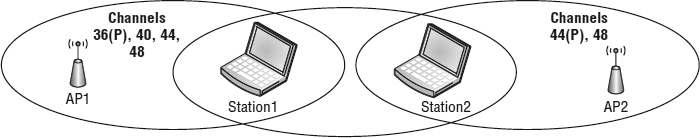
FIGURE 19.13 Dynamic bandwidth operation using RTS/CTS
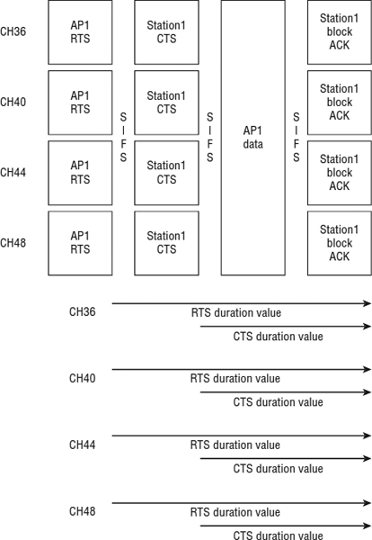
When AP1 receives all four CTS frames, it knows that all four channels are available and reserved and it can perform an 80 MHz data transmission. After the data is transmitted and the data frame is received correctly, Station1 will send four block ACK frames.
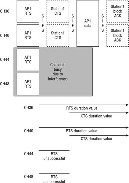
So, what happens if all four channels are not available? Figure 19.14 shows this process. AP1 begins by sending RTS frames across the four channels that make up its 80 MHz channel. In this example, let us assume that Station2 was also transmitting a frame when AP1 was transmitting the RTS frames. Because Station2 is transmitting, Station1 does not receive the RTS frames on channels 44 and 48 but does receive them on channels 36 and 40. Station1 proceeds to reply to AP1 with CTS frames on channels 36 and 40. When AP1 receives the CTS frames, it performs a 40 MHz data transmission on channels 36 and 40. Station1 then responds with two block ACK frames.
FIGURE 19.14 Dynamic bandwidth operation using RTS/CTS
Beamforming
It is time for the revolutionary part of this chapter, and beamforming is the first piece of it. We have to admit, this is a really cool technology. To begin, beamforming can occur from the AP to the client, or vice versa. However, for our initial explanation, let us use an example of beamforming from an AP to a client.
Access points and clients typically have omnidirectional antennas that radiate the RF signal fairly equally and consistently as the signal travels horizontally away from the antenna. Instead of equally radiating the RF signal, beamforming allows an 802.11 transmitter to focus or direct the RF energy toward a specific client.
To perform beamforming, the multiple radio chains in the AP transmit the same information through different antennas. The APs time their transmissions so that the waves of all of the antennas arrive at the receiving radio at the same time and in phase with each other. This should result in a signal increase of approximately 3 decibels. This increase in signal strength can move the communications between the radios to a higher data rate. The increase will not likely be sufficient to affect the higher 256-QAM data rates (or the lower data rates), but it will affect communications in the middle data rate ranges.
802.11ac calls the transmitting radio the beamformer and the receiving radio the beamformee. Beamforming can be adjusted on a frame-by-frame basis, so for one transmission the AP can be the beamformer and for another the client can be the beamformer. An AP can send a beamformed transmission to a station, and if a station supports multiple radio chains, it can send beamformed frames to the AP.
Explicit Beamforming
The 802.11n amendment defined multiple beamforming methods. However, 802.11ac only uses explicit beamforming and requires support by both the transmitter and receiver in order for beamforming to be used. Explicit beamforming uses an interactive calibration process to identify how to perform the transmission using the multiple radio chains. This process is known as channel sounding.
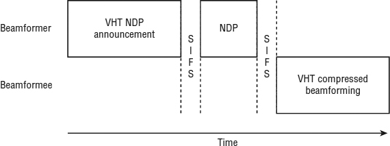
To begin the process, the beamformer transmits a null data packet (NDP) announcement frame, which notifies the beamformee of the intent to send a beamformed transmission. The beamformer then follows this with an NDP frame. The beamformee processes each OFDM subcarrier and creates feedback information. The feedback contains information regarding power and the phase shift between each pair of transmit and receive antennas. This information is used to create a feedback matrix that is then compressed and sent back to the beamformer. This exchange of frames is shown in Figure 19.15. The beamformer uses the feedback matrix to calculate a steering matrix that is used to direct the data transmission to the beamformee.
FIGURE 19.15 Single-user beamform sounding process
Although this section explained the beamforming process, it really explained what is known as single-user beamforming. The next section will introduce you to the most revolutionary part of 802.11ac, known as multiuser MIMO. After explaining multiuser MIMO, we will continue to further explain beamforming, specifically multiuser beamforming.
Multiuser MIMO
So here it is, the 802.11ac technology that changes one of the fundamental concepts of wireless networks, multiuser MIMO (MU-MIMO). Up until now, an 802.11 AP was only able to communicate with one device at a time. When an AP made a transmission, it was addressed to a single client device. With 802.11ac, it is possible to communicate with up to four devices simultaneously. This is being compared with the transition that Ethernet made when layer 1 hubs were replaced by layer 2 switches.
802.11n and 802.11ac APs are capable of transmitting multiple streams of data. However, due to technology costs and battery consumption, many of the most common and popular client devices that are used on wireless networks are only capable of transmitting a single stream of data. This means that when an access point is communicating with a wireless tablet or other handheld device, much of the potential of the technology is not being utilized. 802.11ac provides a solution to this by allowing an AP to communicate with up to four clients simultaneously.
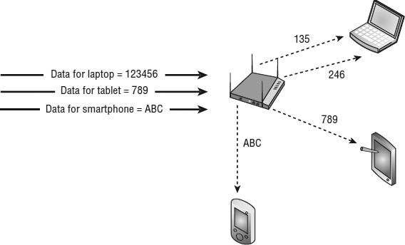
The goal of MU-MIMO is to use as many spatial streams as possible, whether the transmission is with one client using four spatial streams or with four clients using one spatial stream each. Due to the advanced signal processing that is required, MU-MIMO is only supported for downstream transmission from an AP to multiple clients. Figure 19.16 shows an AP that is capable of transmitting four spatial streams. In this illustration, it is using two spatial streams to transmit to a laptop while using a third stream to transmit to a tablet, and a fourth stream is transmitting to an 802.11ac-capable smartphone.
Beamforming is a critical part of MU-MIMO. In a previous section of this chapter, explicit beamforming was explained. In the next section, we will explain how multiuser beamforming is necessary for MU-MIMO to be successful.
Multiuser Beamforming
Earlier in this chapter we explained how 802.11ac performs explicit beamforming, and we also explained the principles of MU-MIMO. It is now time to discuss these two technologies together and the importance of beamforming to the success of MU-MIMO.
With single-user MIMO, beamforming is used to focus a signal to a client. This focused transmission should increase the level of the signal that the client receives—and hopefully allow the AP and client to communicate using a higher data rate than would be possible without beamforming. With MU-MIMO, the task of beamforming is not just performed for transmitting to a single client, it's performed for transmitting to up to four clients at a time.
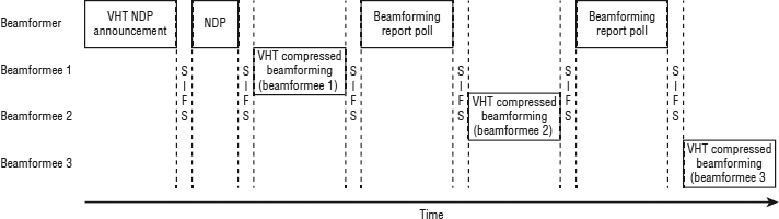
To begin the MU-MIMO beamforming process, the AP performs a channel sounding procedure, similar but more complex than with SU-MIMO. To begin the process, the AP transmits a null data packet (NDP) announcement frame, notifying multiple beamformees of the intent to send a beamformed transmission. The AP then follows this with an NDP frame. As with beamforming to a single user, each beamformee processes each OFDM subcarrier and creates feedback information, creating a compressed feedback matrix. The first beamformee responds to the AP with its compressed feedback matrix. The AP then polls each additional beamformee sequentially using Beamforming Report Poll frames. Figure 19.17 illustrates this process.
FIGURE 19.17 Multiuser beamform sounding process
The AP then uses the feedback matrix from each of the beamformees to create a single steering matrix. The steering matrix defines transmit parameters for communications between each of the antennas on the AP and each of the antennas on each of the client devices, as illustrated in Figure 19.18.
FIGURE 19.18 Beamformed transmissions in a MU-MIMO environment
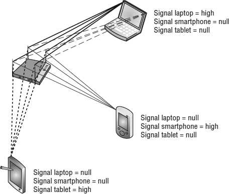
It is important to remember that in Figure 19.18, the AP is sending 16 transmissions, 4 from each antenna. Of those 16 transmissions, the receiving antenna needs to be able to distinguish and interpret the signal that is directed toward it while trying to ignore the other 12 transmissions. Beamformees that are too close to each other could experience inter-user interference from signals directed toward other users. Ideally, the users are physically separated enough from each other and the beamformed signal for the intended user device is strong while that signal received by the other users is low or null. Figure 19.18 illustrates how the different signals should be recognized by the user. If the user devices are separated enough, then the beamformed signal to the intended user should be strong and the signals received by the other users should be null or weak.
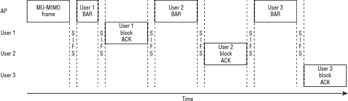
After the AP transmits the multiuser frame, the client stations must each acknowledge its frame. As stated earlier, MU-MIMO is only performed from the AP to the client, so the acknowledgments must be single-user transmissions. Since every 802.11ac frame is an A-MPDU frame, all acknowledgments are performed as block acknowledgments. When a block acknowledgment is required, the originator of the frame, in this case the AP, sends a Block Acknowledgment Request (BAR) frame to the receiver, who replies with a block acknowledgment. Since this is a MU-MIMO frame, the AP sends a BAR frame to a user, waits for the block acknowledgment from that user, and then sequentially repeats the process with the other users. This sequence is illustrated in Figure 19.19.
FIGURE 19.19 MU-MIMO block acknowledgments
Now that you understand how MU-MIMO works in a simplified communications process example with an AP using MU-MIMO to communicate with three client stations (a two spatial stream laptop, a tablet, and a smart phone), it is important for you to realize that an 802.11ac AP could be easily supporting 20 or 30 clients at the same time. Each client is capable of one or more spatial streams. Using Carrier Sense Multiple Access with Collision Avoidance (CSMA/CA), the AP and clients gain access to the media in order to transmit frames between each other. The AP keeps track of the capabilities of each client and goes through the beamforming and block acknowledgment processes for each transmission that it performs. From one transmission to the next, the AP may be sending frames to a different grouping of stations, which would require different matrix information. The AP will periodically need to update its steering matrix in order to redirect or refocus the signal to the new location of a moving beamformee.
Quality of Service
The core concepts and procedures of quality of service (QoS) remain the same with 802.11ac. With the implementation of MU-MIMO, the implementation of the queuing and transmission of QoS frames is handled differently than in single-user wireless environments. As defined previously in the standard, there are four access categories, which are listed here in order of highest to lowest priority:
AC_VO (access category voice)
AC_VI (access category video)
AC_BE (access category best effort)
AC_BK (access category background)
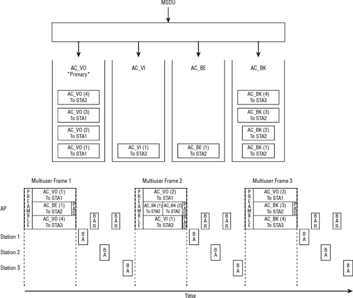
To explain how QoS and MU-MIMO work, we will be referencing Figure 19.20. To begin, as shown at the top of the illustration, the MSDU data is separated into the four access categories. In this example, the AP gains access to the channel to transmit voice data to Station 1. Since the AP gained control to transmit voice data, the AC_VO access category is considered the primary access category, while the other access categories are known as the secondary access categories.
The AP takes the first AC_VO frame for Station 1 and begins to construct a multiuser frame. The AP takes frames for the other stations and adds them to the multiuser frame, providing that the stations are spatially distinct and the frames are shorter than the primary frame. These other frames can be from the primary or secondary access category. Any shorter frames are padded. After the multiuser frame is transmitted to the three stations, block ACKs are used to confirm their successful transmission.
The AP then takes the next AC_VO frame for Station 1 and begins to construct multiuser frame 2. Again, the AP can take frames for the other stations and add them to the multiuser frame. In this instance, two frames destined for Station 2 are short enough that they can both be sent during the time needed to transmit the AC_VO frame to Station 1. Block ACKS are again used to confirm their successful transmission.
A third multiuser frame is constructed, transmitted, and acknowledged. During the construction of each of the multiuser frames, lower-priority frames can piggyback with the higher-priority frame, providing they do not increase the time needed to transmit the primary data and providing the stations they are being sent to are spatially distinct.
Infrastructure Requirements
When transitioning to newer technology, it is often necessary to update some of the infrastructure to support the newer technology. In the case of upgrading to 802.11ac, you will need to assess whether the current PoE equipment will support the new 802.11ac APs. You will also need to consider not if, but when to upgrade the Ethernet network that connects to the APs.
Ethernet
With the transition to the second phase of 802.11ac, the data throughput of the wireless network may exceed Gigabit Ethernet speeds. Currently, first phase 802.11ac APs support up to 450 Mbps of transmission speed on a 2.4 GHz radio (802.11n) and up to 1.3 Gbps of transmission speed on a 5 GHz radio. This works out to about 1.75 Gbps of total transmission speed. Actual maximum throughput will vary but is around two-thirds of the maximum calculated transmission speed, which works out to just slightly greater than a gigabit. Since these rates are maximums under perfect conditions, a single Gigabit Ethernet connection can support a phase one 802.11ac AP. Since 2.4 GHz networks are limited to three nonoverlapping channels, it is not likely that 40 MHz wide channels will be used in an enterprise environment. The realistic maximum transmission speed for 2.4 GHz 802.11n using 20 MHz wide channels is about 216 Mbps for first phase 802.11ac APs.
FIGURE 19.20 MU-MIMO and QoS
The second phase of 802.11ac may require faster uplink technology than Gigabit Ethernet. The second phase of 802.11ac is expected to support channel widths of up to 160 MHz and four spatial streams. Since the AP will support four spatial streams, the 2.4 GHz 802.11n maximum transmission speed will increase from 450 Mbps to 600 Mbps, with the realistic 20 MHz wide channel maximum transmission speed of about 289 Mbps. The maximum transmission speed for the 5 GHz radio will increase to just under 3.5 Gbps. Although some people will have a need for the wider 160 MHz channels, it is not likely that they will be used often. If we consider 80 MHz as the likely or typical maximum channel width, then the maximum transmission speed for the 5 GHz radio will be about 1.7 Gbps. Therefore, with the realistic 2.4 GHz (20 MHz wide channel) speed of 289 Mbps and the 5 GHz (80 MHz wide channel) speed of 1.7 Gbps, the maximum transmission speed is just under 2 Gbps, with maximum throughput of the AP of about 1.3 Gbps.
So, if second phase 802.11ac is capable of data rates of up to 1.3 Gbps, what options are available for providing this throughput on the distribution system? An initial thought may be to consider 10 Gbps Ethernet; however, 10 Gbps copper Ethernet is not commonly available, and at the time that we wrote this book, there was no PoE option available for 10 Gbps copper. Another option would be to use 10 Gbps fiber from the switch to the AP. The problem with using fiber is that it does not support PoE, and therefore if it is used, power would have to be provided using another method. The most obvious option is to equip the AP with two 1 Gbps Ethernet ports and to run two 1 Gbps Ethernet cables to each 802.11ac AP. AP vendors will likely bond the two Ethernet channels together to provide up to 2 Gbps of throughput. It is important to remember that these suggestions are based upon using a second phase AP, with four spatial streams. It is likely that second phase APs will be available that support fewer than four spatial streams and will function well with a single gigabit Ethernet connection.
802.11ac APs and Dual Ethernet Cables
Since the next phases of 802.11ac will eventually require more than 1 Gbps to backhaul the data, two Ethernet cables will be necessary to take advantage of the additional bandwidth requirements.
Power
When companies first began to install 802.11 APs, it was common to use power bricks or mid-span PoE injectors to provide power to the APs. By the time most companies had installed or upgraded to 802.11g or 802.11n, most of these APs were being powered by PoE-capable Ethernet switches. The majority of enterprise APs are able to be powered by 802.3af-compliant PoE.
As companies transition to 802.11ac APs, transitioning to PoE+ will be inevitable. The greater the performance of the AP, the more likely that additional power will be needed. The industry is transitioning to PoE+. Some 802.11ac APs can operate using 802.3af PoE, whereas other APs restrict some features if 802.3af is used instead of PoE+. Still other APs specify that PoE+ is mandatory.
With the second phase of 802.11ac, it is more likely that these APs will require PoE+ and that a single 802.3af-powered cable will not provide enough power. As future phases of 802.11ac are implemented, in addition to providing connectivity to an AP using two Ethernet ports, the Ethernet cables could both be used to provide PoE to the AP. If the existing infrastructure only supports 802.3af power, each cable could carry the 15.4 watts of power that 802.3af PoE provides for a total of 30.8 watts. While this scenario may be possible by some vendors' 802.11ac APs, upgrading the network to provide 802.3at (PoE+) power of 30 watts is highly recommended and most likely will become a necessity.
802.11ac in a SOHO or Home
Since you are reading this book, it is likely that you are someone who likes technology toys—or you know someone who does. Or maybe you are someone (or know someone) who just wants the best or fastest of whatever they are buying. In the past, as newer 802.11 PHYs were introduced to the market, there typically has been a benefit to the SOHO or home user to upgrade to the newer PHY. 2 Mbps 802.11 was replaced by 11 Mbps 802.11b, which was replaced with 54 Mbps 802.11g, which was then replaced by 300 Mbps or 450 Mbps 802.11n. During each of these migrations, the faster transmission speed could often be justified and provided real increases in performance to the users. So, the question now is, Will installing or migrating to 802.11ac be beneficial in a SOHO or home environment? There is no right answer to this question, but there are numerous pieces to evaluate when considering migrating.
Although the following sections focus on the SOHO and home environment, much of the decision making is also valid for enterprise environments. We try to break out and summarize what you learned in this chapter, from a technology and practical perspective. Hopefully this will help you as you decide your 802.11ac migration path and timeline.
Device Radios
One of the first things to determine is whether the client devices that you will be using support 802.11ac. If you purchase a new laptop or phone, it is likely that they support 802.11ac. Do all of your other devices? Remember that 802.11ac uses only 5 GHz transmissions. This is not compatible with any 2.4 GHz 802.11b/g/n devices you may still be using. Printers, scanners, tablets, gaming devices, TVs, Blu-ray players, and many other devices that you already own probably do not support 5 GHz. Therefore, if you do plan to upgrade, you will need to purchase a dual-radio AP to continue to provide support for older 2.4 GHz devices.
Data Flow/Usage
Another consideration for whether or not to upgrade to 802.11ac is to determine if you will gain any benefit from the additional speed. Unless you have an unusual network configuration, your communications will be either between your client device and the Internet or between your client device and some type of server within your network. If your communication is out to the Internet, it is not likely that your Internet connection is fast enough to support the throughput that an 802.11ac AP can provide. If your communication is to a server within your network, you will need to find out whether the server can handle the faster data rates. If it can, you will need to ensure that the entire datapath between the AP and the server supports at least 1 Gbps Ethernet.
Spatial Streams
Many personal mobile devices do not support multiple spatial streams due to the power requirements. If you are operating 802.11ac multiple-spatial-stream devices along with single-spatial-stream devices, the single-stream devices will decrease the performance of the faster devices. You will need to consider how your faster devices are affected and whether the performance you achieve is worth the upgrade costs.
Wider 802.11ac Channels
With channel widths up to 80 MHz and 160 MHz with the second phase of 802.11ac, the wider channel width is a technology that all 802.11ac devices can benefit from. Although it takes more power to process the data that is transmitted across wider channels because more subcarriers are being transmitted, the faster data rates along with mandatory A-MPDU support actually reduces transmission time and power consumption. A single spatial stream device can achieve transmission speeds of up to 433 Mbps using an 80 MHz channel and up to 866 Mbps with 160 MHz channels.
MU-MIMO
MU-MIMO does have the potential of improving performance in the SOHO or home environment. With CSMA/CA technology, slower devices affect the overall performance of the network for all devices. With MU-MIMO, the AP can transmit to up to four devices simultaneously. Instead of four 433 Mbps single-stream devices splitting the transmission, MU-MIMO allows multiple downstream transmissions to occur simultaneously, theoretically providing up to four simultaneous 433 Mbps communications. You need to remember that this can only occur if the devices are spatially separated, since beamforming will not work properly if two devices are near each other.
Wi-Fi Alliance Certification
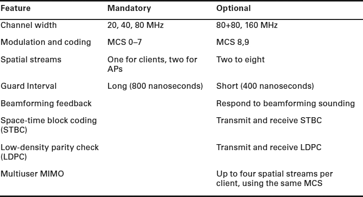
In June 2013, prior to the ratification of the 802.11ac amendment, the Wi-Fi Alliance published its vendor certification program for 802.11ac, Wi-Fi CERTIFIED ac. 802.11ac products are tested for both the mandatory and optional baseline capabilities listed in Table 19.5. As with Wi-Fi CERTIFIED n products, Wi-Fi CERTIFIED ac products must support both Wi-Fi Multimedia (WMM) quality-of-service mechanisms and WPA2/WPA2 security mechanisms. Unlike Wi-Fi CERTIFIED n devices, Wi-Fi CERTIFIED ac devices do not operate in both the 2.4 GHz and 5 GHz frequency bands. Wi-Fi CERTIFIED ac devices only operate in the 5 GHz frequency band. As stated earlier in this chapter, this is due to the limited frequency range available in the 2.4 GHz ISM band. Therefore, they only need to be backward compatible with 5 GHz 802.11a/n certified devices.
TABLE 19.5 Wi-Fi CERTIFIED ac baseline requirements (phase 1)
Summary
In this chapter, you learned about the 802.11ac amendment, how the amendment is currently implemented, and the migration path with future phases of the standard. We also discussed all the methods used by VHT radios to increase throughput and range at the Physical layer. We explained the evolutionary updates to 802.11ac: 5 GHz only, channel widths up to 160 MHz, enhanced modulation with 256-QAM, and mandatory A-MPDU for all frames. The most exciting part of 802.11ac (and the revolutionary aspect of the amendment) is the introduction of MU-MIMO, which allows an AP to transmit to multiple client stations simultaneously. Some of the technologies are being implemented in the first products released; others will follow in multiple phases of future implementation. 802.11ac has great potential.
If you are interested in learning more about 802.11ac, we recommend that you read 802.11ac: A Survival Guide by Matthew Gast (O'Reilly Media, 2013). Matthew has done an excellent job of explaining the core technologies that make up 802.11ac, in an in-depth and concise format.
Exam Essentials
Define the differences between 802.11n and 802.11ac. Understand how 802.11ac is similar and different than 802.11n. Know which 802.11ac technologies are evolutionary and which are revolutionary. Explain why 802.11ac is only being implemented in the 5 GHz band.
Understand 20 MHz, 40 MHz, 80 MHz, and 160 MHz channels. Understand the differences between 20 MHz, 40 MHz, 80 MHz, and 160 MHz channels. Explain how 160 MHz channels are actually two 80 MHz channels. Explain how 802.11ac radios will dynamically switch to narrower channels if the wider channel is not available. Describe the importance of primary channel selection for each channel width.
Understand 64-QAM and 256-QAM. Explain how 256-QAM is similar and how it is different than 64-QAM. Describe the significance of the constellation chart and the pros and cons of the denser 256-QAM.
Explain MCS. Explain the transition from 77 MCSs in 802.11n and 10 MCSs in 802.11ac. Explain why 802.11ac does not allow individual data rates to be enabled or disabled.
Describe explicit beamforming. Describe the communications between the AP and the client to perform explicit beamforming. Describe the benefits of explicit beamforming.
Explain the difference between SU-MIMO and MU-MIMO. Explain how many spatial streams are supported by 802.11ac along with the additional resources necessary to implement more spatial streams. Explain the technological differences between sending a SU-MIMO signal and a MU-MIMO.
Explain MU-MIMO. Explain the MU-MIMO process and the conditions under which it will be most successful. Explain how beamforming makes this possible. Explain the requirements for adding more spatial streams. Explain how QoS is implemented in a MU-MIMO environment.
Understand 802.11ac data rates. Understand how MCS, spatial streams, and channel width determine the maximum data rate achievable by a device.
Understand the infrastructure requirements of 802.11ac. Understand how the Ethernet and PoE requirements are affected by an 802.11ac deployment.
Describe the concerns when deploying 802.11ac in any environment. Describe how user devices, data flow, spatial streams, channel width, and MU-MIMO need to be taken into consideration when evaluating whether to migrate to an 802.11ac environment.
Review Questions
- Which of the following technologies was optional in 802.11n and now mandatory in 802.11ac?
- MIMO
- RIFS
- A-MPDU
- A-MSDU
- SU-MIMO
- With the first phase of 802.11ac supporting three spatial streams, what is the maximum transmission speed?
- 600 Mbps
- 1.3 Gbps
- 3.5 Gbps
- 6.933 Gbps
- 7.0 Gbps
- Which of the following modulation methods are supported with 802.11ac? (Choose all that apply.)
- BPSK
- BASK
- 32-QAM
- 64-QAM
- 256-QAM
- Which of the following channel widths are supported in 802.11ac? (Choose all that apply.)
- 20 MHz
- 40 MHz
- 80 MHz
- 80+80 MHz
- 160 MHz
- When a 160 MHz wide channel is used, how many primary channels are defined?
- 1
- 2
- 3
- 4
- None
- Using 256-QAM, how many bits are represented by each subcarrier?
- 1
- 2
- 4
- 6
- 8
- How many modulation and coding schemes are defined in 802.11ac?
- 8
- 10
- 64
- 77
- 256
- Which 802.11ac MCS range defines all of the MCSs that are mandatory?
- MCS 0–2
- MCS 0–4
- MCS 0–6
- MCS 0–7
- MCS 0–8
- MCS 0–9
- The 802.11ac amendment defines a maximum of how many spatial streams for an AP, and how many maximum devices can an AP communicate with at once?
- One spatial stream, four devices
- One spatial stream, eight devices
- Four spatial streams, four devices
- Eight spatial streams, four devices
- Eight spatial streams, eight devices
- Requiring all frames to be transmitted as A-MPDU frames increases performance due to which of the following? (Choose all that apply.)
- Frame overhead is reduced.
- Block ACK is required.
- Frame information is shifted from the MPDU header to the PLCP header.
- Reduced Interframe Space (RIFS) decreases the amount of time between frames.
- A-MSDU is required; A-MPDU is optional.
- Which of the following technologies is part of explicit beamforming? (Choose all that apply.)
- Channel sounding
- Feedback matrix
- Sounding matrix
- Steering matrix
- Null data packet
- Channel matrix
- What is the main reason that many smartphones do not support multiple spatial streams?
- It is difficult to install multiple antennas in the smart phone.
- The size of the necessary technology would make the smartphone larger than desired.
- Battery consumption would be too great.
- Most smartphones actually do support four spatial streams.
- Which of the following are QoS categories? (Choose all that apply.)
- AC_VO (access category voice)
- AC_DA (access category data)
- AC_VI (access category video)
- AC_BE (access category best effort)
- AC_BK (access category background)
- When transmitting a QoS frame using MU-MIMO, which of the following statements is true? (Choose all that apply.)
- Voice frames are always transmitted before lower-priority frames.
- The category that is used to take control of the transmission is known as the primary access category.
- If a lower category frame is transmitted, only higher category frames can be transmitted using the other spatial streams.
- Lower category frames can be transmitted as long as they do not increase the transmission duration of the primary access category.
- Multiple lower category frames can be transmitted along with the primary access category frame.
- Name some of the factors that a modulation and coding scheme (MCS) uses to define data rates for a VHT radio? (Choose all that apply.)
- Modulation method
- Equal/unequal modulation
- Number of spatial streams
- GI
- Channel size
- Code rate
- Which of these capabilities are considered mandatory for a phase one 802.11ac access point as defined by the Wi-Fi Alliance's vendor certification program called Wi-Fi CERTIFIED ac? (Choose all that apply.)
- 20, 40, 80, 160 MHz channel
- MCS 0–7
- MCS 0–8
- Two spatial streams
- Long guard interval
- VHT radios are backward compatible with which of the following type of 802.11 technology? (Choose all that apply.)
- Clause 17 radios (HR-DSSS)
- Clause 18 radios (OFDM)
- Clause 14 radios (FHSS)
- Clause 19 radios (ERP)
- Clause 20 radios (HT)
- Which of the following statements is not true regarding the number of subcarriers in the following channels? (Choose all that apply.)
- 40 MHz subcarriers = 2 times 20 MHz subcarriers
- 40 MHz subcarriers > 2 times 20 MHz subcarriers
- 80 MHz subcarriers = 2 times 40 MHz subcarriers
- 80 MHz subcarriers > 2 times 40 MHz subcarriers
- 160 MHz subcarriers = 2 times 80 MHz subcarriers
- 160 MHz subcarriers > 2 times 80 MHz subcarriers
- The 802.11ac amendment defines a maximum of how many spatial streams for client?
- One spatial stream
- Two spatial streams
- Four spatial streams
- Eight spatial streams
- Which 802.11ac technology is the most revolutionary?
- 80 MHz and 160 MHz channel widths
- A-MPDU for all frames
- 256-QAM modulation
- 5 GHz only frequencies
- MU-MIMO
- Explicit beamforming