IN THIS CHAPTER, YOU WILL LEARN ABOUT THE FOLLOWING:
- History of PoE
- Nonstandard PoE
- IEEE 802.3af
- IEEE Std 802.3-2005, Clause 33
- IEEE 802.3at-2009
- IEEE Std 802.3-2012, Clause 33
- PoE devices (overview)
- Powered device (PD)
- Power-sourcing equipment (PSE)
- Endpoint PSE
- Midspan PSE
- Power-sourcing equipment pin assignments
- Planning and deploying PoE
- Power planning
- Redundancy
- 802.11n or 802.11ac and PoE
 In this chapter, you will learn about the various ways that an Ethernet cable can be used to provide power to networking devices. Power over Ethernet (PoE) is not a Wi-Fi technology, nor is it used specifically for Wi-Fi devices. However, it has become the predominant method for powering enterprise-class access points, thus making it a necessary and important topic when discussing wireless networking.
History of PoE
Before we begin this chapter, we need to explain what PoE is. Over the years, computer networking typically entailed connecting a stationary, electrically powered computer system to a wired network. The computers were anything from desktop PCs to servers and mainframes. As is typical with technology, larger computers gave way to smaller computers, and laptop and portable devices began to appear. Eventually, some of the networking devices became small enough, both physically and electronically, that it became possible and practical not only to use the Ethernet cable to transmit data to the device, but also to send the electricity necessary to power the device.
The concept of providing power from the network dates back to the birth of the telephone, which to this day still receives power from the telephone network. Computer networking devices that are often powered with PoE are desktop Voice over IP (VoIP) phones, cameras, and access points. Ethernet cables consist of four pairs of wires. With 10 Mbps and 100 Mbps Ethernet, two pairs are used for transmitting and receiving data and the other two pairs are unused. Gigabit Ethernet uses all four pairs of wires to transmit and receive data. As you will see later in this chapter, this is not a problem, since PoE can provide power on the unused wires or on the same wires that are used to transmit and receive data.
When you are providing power to devices via the same Ethernet cable that provides the data, a single low-voltage Ethernet cable is all you need to install a networked PoE device. The use of PoE devices alleviates the need to run electrical cables and outlets to every location that needs to be connected to the network. Not only does this greatly reduce the cost of installing network devices, it also increases flexibility in terms of where these devices can be installed and mounted. Moving devices is also easier, because all that is required at the new location is a PoE-powered Ethernet cable.
Nonstandard PoE
As with most new technologies, the initial PoE products were proprietary solutions created by individual companies that recognized the need for the technology. The IEEE process to create a PoE standard began in 1999; however, it would take about four years before the standard became a reality. In the meantime, vendor-proprietary PoE continued to proliferate. Proprietary PoE solutions often used different voltages, and mixing proprietary solutions could result in damaged equipment.
IEEE 802.3af
The IEEE 802.3af Power over Ethernet committee created the PoE amendment to the 802.3 standard. It was officially referred to as IEEE 802.3 “Amendment: Data Terminal Equipment (DTE) Power via Media Dependent Interface.” This amendment to the IEEE 802.3 standard was approved on June 12, 2003, and defined how to provide PoE to 10BaseT (Ethernet), 100BaseT (Fast Ethernet), and 1000BaseT (Gigabit Ethernet) devices.
IEEE Std 802.3-2005, Clause 33
In June 2005, the IEEE revised the 802.3 standard, creating IEEE Std 802.3-2005. The 802.3af amendment was one of four amendments that were incorporated into this revised standard. In the 2005 revision of the 802.3 standard, and in the more recent revisions (it was revised in 2008, and again in 2012), Clause 33 is the section that defines PoE.
IEEE 802.3at-2009
The IEEE 802.3at amendment was ratified in 2009. 802.3at is also known as PoE+ or PoE plus, since it extends the capabilities of PoE as originally defined in the 802.3af amendment. Two of the main objectives of the 802.3at Task Group were to be able to provide more power to powered devices and to maintain backward compatibility with Clause 33 devices. As APs become faster and incorporate newer technologies, such as multiple input, multiple output (MIMO), they require more power to operate. Switches and controllers that incorporate 802.3at technology are able to provide power to legacy APs as well as newer APs that require more power. The IEEE 802.3at amendment is able to provide up to 30 watts of power using two pairs of wires in an Ethernet cable. The 802.3at amendment defines PoE devices as either Type 1 or Type 2. Devices capable of supporting the higher power defined in the 802.3at amendment are defined as Type 2 devices, and devices not capable of supporting the higher power are defined as Type 1 devices.
Typically, when an 802 amendment is created and ratified, the amendment document is essentially a series of additions, deletions, and edits that modify and update the base standard. With 802.3at, the PoE section (Clause 33) of the 802.3-2008 standard was entirely replaced by the 802.3at amendment.
IEEE Std 802.3-2012, Clause 33
In December 2012, the IEEE revised the 802.3 standard again and created IEEE Std 802.3-2012. Just as the 802.3af amendment had been incorporated into the 802.3 standard in 2005, with the release of the 802.3-2012 revised standard, the 802.3at amendment was officially incorporated into this new revision. Clause 33 of the IEEE Std 802.3-2012 now included the higher power capabilities defined by the 802.3at amendment.
An Overview of PoE Devices
The PoE standard defines two types of PoE devices: powered devices (PDs) and power-sourcing equipment (PSE). These devices communicate with each other and provide the PoE infrastructure.
Powered Device
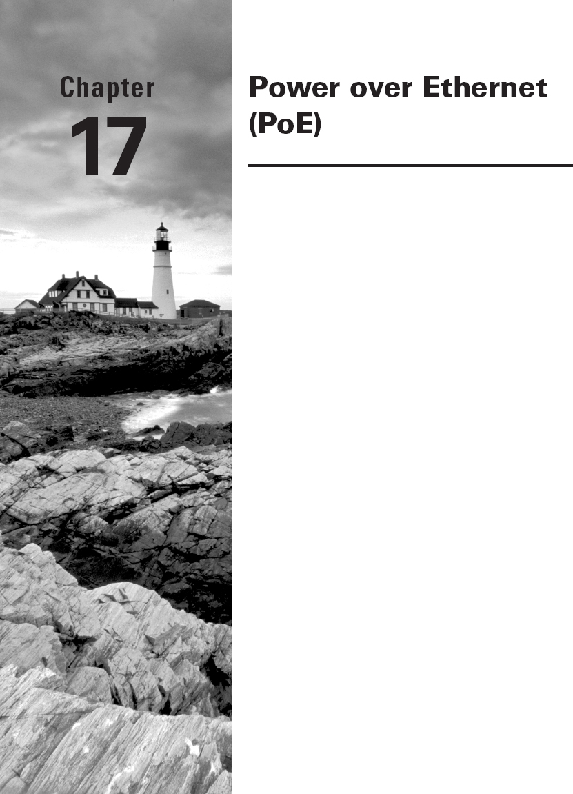
The powered device (PD) either requests or draws power from the power-sourcing equipment. PDs must be capable of accepting up to 57 volts from either the data lines or the unused pairs of the Ethernet cable. The PD must also be able to accept power with either polarity from the power supply in what is known as mode A or mode B, as described in Table 17.1.
TABLE 17.1 PD pinout
The PD must reply to the power-sourcing equipment with a detection signature and notify the power-sourcing equipment whether it is in a state in which it will accept power or will not accept power. The detection signature is also used to indicate that the PD is compliant with 802.3-2012, Clause 33. If the device is determined not to be compliant, power to the device will be withheld. If the device is in a state in which it will accept power, the PD can optionally provide a classification signature. This classification signature lets the power-sourcing equipment know how much power the device will need.
Type 2 devices perform a two-event Physical layer classification or Data-Link layer classification, which allows a Type 2 PD to identify whether it is connected to a Type 1 or a Type 2 PSE. If mutual identification cannot be completed, the device can only operate as a Type 1 device.
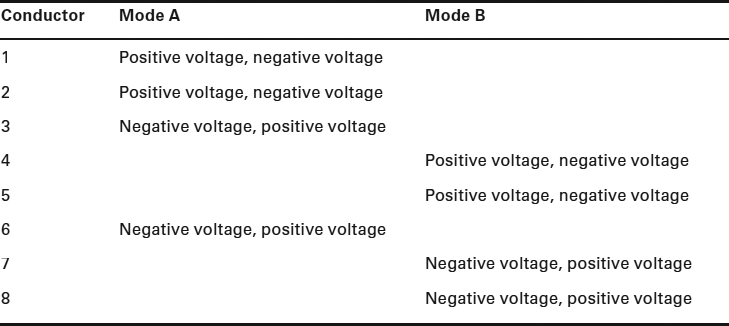
Table 17.2 lists the current values used to identify the various classification signatures. If none of these current values are measured, the device is considered to be a Class 0 device. If the device is not identified, the PSE does not know how much power the device needs; therefore, it allocates the maximum power. If the device is classified, the PSE has to allocate only the amount of power needed by the PD, thus providing better power management. Proper classification of the devices can lead to a managed reduction in power usage and can also enable you to connect more devices to a single PoE-capable switch.
TABLE 17.2 PD classification signature measured electrical current values
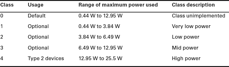
In the past, some vendors used proprietary layer 2 discovery protocols to perform classification. Although these techniques are good from the power-management and consumption perspective, they are proprietary and will not work with other manufacturers' products. Link Layer Discovery Protocol (LLDP) is a standards-based layer 2 neighbor discovery protocol that can also be used for more detailed power classification. Table 17.3 lists the classes of PoE devices and the range of maximum power that they use. Power classes 0 to 3 are for Type 1 devices that will work with 802.3af power sourcing equipment. Power class 4 is meant for Type 2 devices that work with 802.3at (PoE+) power sourcing equipment. The maximum power draw of an 802.3af-compliant device is 12.95 watts, and the maximum power draw of an 802.3at-compliant device is 25.5 watts.
TABLE 17.3 PD power classification and usage
Can 802.3af-Compliant Access Points Use More Power?
Although a PSE port might offer 15.4 watts of power, the maximum draw of an 802.3af-compliant PD is 12.95 W. For example, an access point might use as much as 12.95 W on CAT3 cabling or higher. The power draw is always lower than the original power source because of insertion loss from the cable. In reality, a PD might be able to draw more power if higher grade cabling is used. For example, a 3x3:3 MIMO access point might actually need 14.95 W to operate with full functionality. Most WLAN vendors will recommend the use of CAT5e cabling or better so that 802.11n access points can draw more than 12.95 W and fully power all the MIMO radios.
Power-Sourcing Equipment
The power-sourcing equipment (PSE) provides power to the PD. The power supplied is at a nominal 48 volts (44 volts to 57 volts). The PSE searches for powered devices by using a direct current (DC) detection signal. After a PoE-compliant device is identified, the PSE will provide power to that device. If a device does not respond to the detection signature, the PSE will withhold power. This prevents noncompliant PD equipment from becoming damaged.
As you can see in Table 17.4, the amount of power provided by the PSE is greater than what is used by the PD (Table 17.3). This is because the PSE needs to account for the worst-case scenario, in which there may be power loss due to the cables and connectors between the PSE and the PD. The maximum draw of any powered device is 25.5 watts. The PSE can also classify the PD if the PD provided a classification signature. Once connected, the PSE continuously checks the connection status of the PD along with monitoring for other electrical conditions, such as short circuits. When power is no longer required, the PSE will stop providing it. Power-sourcing equipment is divided into two types of equipment: end-point and midspan.
| Class | Minimum power from the PSE |
| 0 | 15.4 W |
| 1 | 4.0 W |
| 2 | 7.0 W |
| 3 | 15.4 W |
| 4 | 30.0 W |
Endpoint PSE
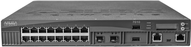
An endpoint PSE provides power and Ethernet data signals from the same device. Endpoint devices are typically PoE-enabled Ethernet switches, such as the 48-port switch shown in Figure 17.1. Because the PoE-enabled switches are used to power access layer devices (such as APs and phones), the switches are typically access layer switches, as opposed to distribution or core switches. Some specialty devices, such as WLAN controllers (as shown in Figure 17.2), may also function as endpoint PSE equipment. Most controller-based APs are powered by an access layer switch; however, some of the smaller model or branch WLAN controllers might also be used to power access points.
FIGURE 17.1 Aerohive SR2048P: 48-port Gigabit Ethernet access switch with PoE
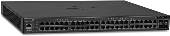
FIGURE 17.2 An Aruba 7010 wireless controller with PoE
Endpoint equipment can provide power using two methods referred to as Alternative A and Alternative B:
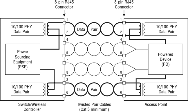
Alternative A With Alternative A, the PSE places power on the data pair. Figure 17.3 shows how a 10BaseT/100BaseTX endpoint PSE provides power using Alternative A, and Figure 17.4 shows how a 1000BaseT endpoint PSE provides power using Alternative A.
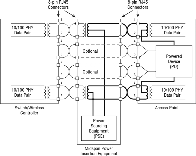
Alternative B Originally, Alternative B was designed to provide power on the spare unused pair of wires in a 10BaseT/100BaseTX cable, as shown in Figure 17.5. A 1000BaseT endpoint PSE can also use Alternative B to provide power to a PD by placing the power on two of the data 1000BaseT data pairs, as depicted in Figure 17.6. Endpoint PSE is compatible with 10BaseT (Ethernet), 100BaseTX (Fast Ethernet), and 1000BaseT (Gigabit Ethernet). When 802.3af was initially ratified, 1000BaseT (Gigabit Ethernet) devices could receive PoE from only endpoint devices.
In the next section of this chapter, you will see that that is no longer true. With the ratification of 802.3at, 1000BaseT devices could also be powered using either endpoint PoE or midspan PoE.
FIGURE 17.3 10BaseT/100BaseTX endpoint PSE, Alternative A
Midspan PSE
A midspan PSE acts as a pass-through device, adding power to an Ethernet segment. Midspan equipment enables you to provide PoE to existing networks without having to replace the existing Ethernet switches. A midspan PSE is placed between an Ethernet source (such as an Ethernet switch) and a PD. The midspan PSE acts as an Ethernet repeater while adding power to the Ethernet cable. Originally with 802.3af, midspan devices were only capable of using Alternative B—and only with 10BaseT and 100BaseTX PDs. With the ratification of 802.3at, midspan devices were able to use either Alternative A or Alternative B and they could provide support for 1000BaseT devices.
FIGURE 17.4 1000BaseT endpoint PSE, Alternative A

Figure 17.7 shows how a 10BaseT/100BaseTX midspan PSE provides power using Alternative A, and Figure 17.8 shows how a 1000BaseT midspan PSE provides power using Alternative A. Figure 17.9 shows a 10BaseT/100BaseTX midspan PSE providing power using Alternative B, and Figure 17.10 shows how a 1000BaseT midspan PSE provides power using Alternative B.
Figure 17.11 shows a single-port midspan device, along with three multiport devices. The midspan PSE is commonly known as a power injector (single-port device) or a PoE hub (multiport device).
Figure 17.12 shows three typical ways of providing power to a PD. Option 1 illustrates an endpoint PoE-enabled switch with inline power. This switch provides both Ethernet and power to the AP. Option 2 and Option 3 illustrate two methods of providing midspan power. Option 2 shows a multiport midspan PSE commonly referred to as an inline power patch panel, and Option 3 shows a single-port midspan PSE commonly referred to as a single-port power injector.
FIGURE 17.5 10BaseT/100BaseTX endpoint PSE, Alternative B
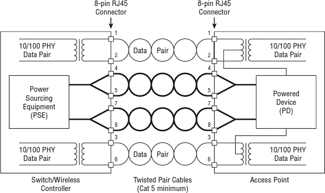
FIGURE 17.6 1000BaseT endpoint PSE, Alternative B
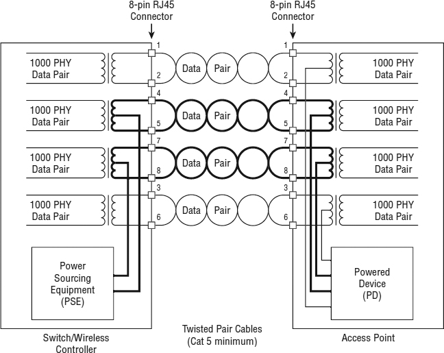
FIGURE 17.7 10BaseT/100BaseTX midspan PSE, Alternative A
Power-Sourcing Equipment Pin Assignments
The power-sourcing equipment (PSE) must have a medium dependent interface (MDI) to carry the current to the powered device (PD). MDI is essentially the technical term for the Ethernet cabling connector. Keep in mind that the Ethernet maximum distance limitations of 100 meters (328 feet) still apply when PoE mechanisms are utilized.
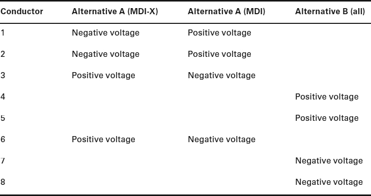
There are two valid four-wire pin connections used to provide PoE. In each of these configurations, the two pairs of conductors carry the same nominal current in both magnitude and polarity. When you power a device using Alternative A, the positive voltage is matched to the transmit pair of the PSE. The input pairs of an Ethernet cable must connect to the output pairs of the device it is connected to. This is known as medium dependent interface crossover (MDIX or MDI-X). Many devices are capable of automatically identifying and providing the crossover connection if needed. If a PSE is configured to automatically configure MDI/MDI-X (also called Auto MDI-X, or automatic crossover), the port may choose either Alternative A polarity choice, as described in Table 17.5.
FIGURE 17.8 1000BaseT midspan PSE, Alternative A
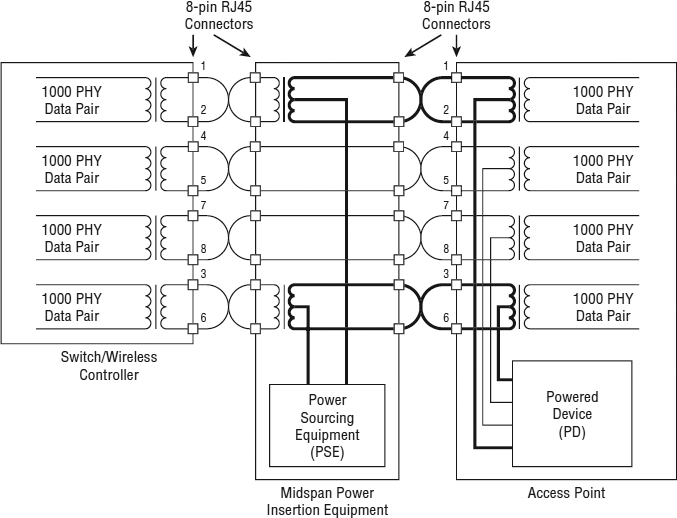
FIGURE 17.9 10BaseT/100BaseTX midspan PSE, Alternative B
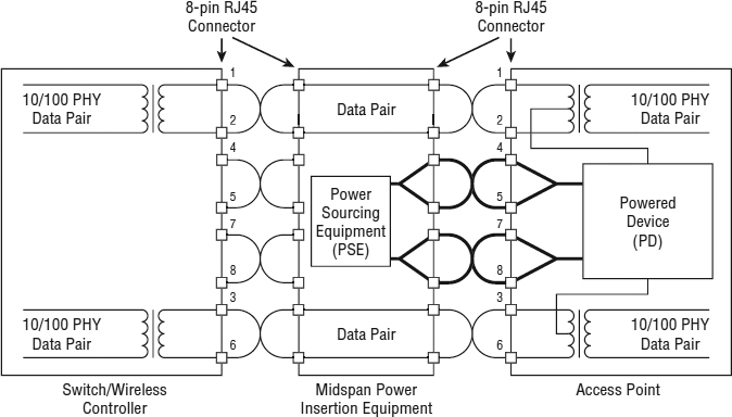
FIGURE 17.10 1000BaseT midspan PSE, Alternative B
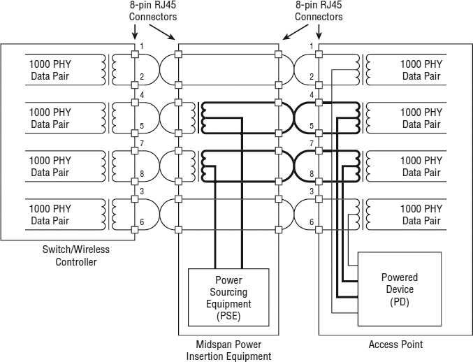
FIGURE 17.11 PowerDsine power injector and PoE hubs
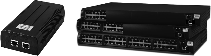
FIGURE 17.12 Three PSE solutions
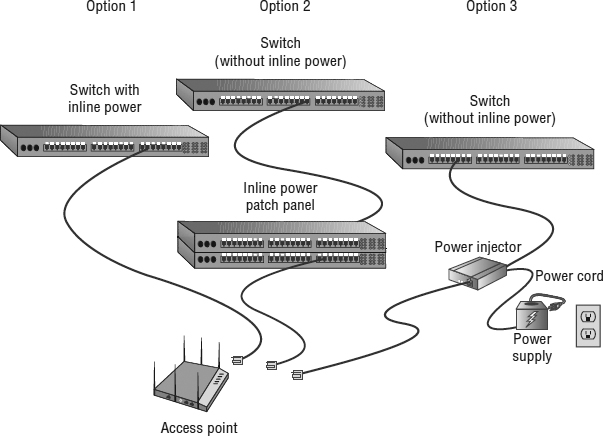
TABLE 17.5 PSE pinout alternatives
Planning and Deploying PoE
In the past, when non-PoE desktop VoIP telephones and APs were connected to the network, each device had to be individually plugged into a power outlet. These outlets were spread around the building or campus, distributing the power needs. PoE now consolidates the power source to the wiring closet or data center, requiring that only an Ethernet cable be connected to the PoE-powered device.
Power Planning
Instead of the power being distribued for hundreds or thousands of devices, the power for these devices is now being sourced from either a single or a limited number of locations. At maximum power for a PD, the PSE must be capable of providing 15.4 W or 30 W of power to each PoE device, depending on whether your devices require PoE+. Assuming that your PDs do not require PoE+, this means that a typical PoE-enabled 24-port Ethernet switch must be able to provide about 370 watts of power to provide PoE to all 24 ports (15.4 watts × 24 ports = 369.6 watts). This does not include the amount of power necessary for the switch to perform its networking duties. A simple way of determining whether the power supply of the switch is powerful enough is to determine the size of the power supply for the equivalent non-PoE switch and add 15.4 watts for each PoE device that you will be connecting to the switch, or 30 watts for each PoE+ device you will be connecting to the switch.
The maximum power a 110-volt power supply is capable of providing is 3,300 watts (110 volts × 30 amperes). Let's assume that a wiring closet is supplied with a 110 volt, 15 amp circuit (1,650 watts), which is not uncommon. Enterprise-grade PoE-enabled switches often consist of multiple 48-port line cards housed in a chassis. The chassis itself may require 1,000 to 2,000 watts. If the 48-port line cards draw 15.4 watts per port, a total power draw of 740 watts would be required. Depending on the power requirements of the chassis, 3,300 watts would be able to power only the chassis and two to three fully populated 48-port line cards.
Because many devices such as 802.11 APs, video cameras, and desktop VoIP phones may require power, situations often arise where there simply is not enough available wattage to power all the PoE ports. Network engineers have begun to realize the need and importance for a power budget. Careful planning is needed to ensure that enough power is available for all the PDs. Powered devices that are capable of classification can greatly assist in conserving energy and subtracting less power from the power budget. A device that needs to draw 3 watts and is not capable of providing a classification signature would be classified as Class 0 by default and subtract 15.4 watts from the power budget. Effectively, 12 watts of power would be wasted. If that same device was capable of providing a classification signature and was classified as a Class 1 device, only 4 watts would be subtracted from the power budget. Classification of PDs will grow in importance as the need for 802.11 deployments grows.
Enterprise switch vendors will list the PoE power budget within the switch specification sheet. The PoE power budget listed in a spec sheet is indeed the amount of power that is available to the ports and is not earmarked for other switch functions. When reading the power budget specifications of a switch, be sure to determine how many ports are PoE-capable. For example, Vendor-A might have a 24-port gigabit switch with a PoE power budget of 195 watts, but the budget is only available to 8 of the 24 ports. Vendor-B might also offer a 24-port gigabit switch with a PoE power budget of 195 watts, but the budget can be available to any of the 24 ports. Vendor-C might sell a 24-port switch with a much larger PoE power budget of 408 watts available to all 24 ports. Keep in mind: The larger the power budget, the cost of the PoE-enabled switch rises significantly.
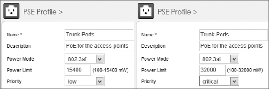
As shown in Figure 17.13, most switches have the ability to designate whether the port is a standard 802.3af port or 802.3at (PoE+) port. An 802.11a/b/g/n access point will normally need the full 15.4 watts provided by an 802.3af port; however, a VoIP desktop phone might only need 7 watts from the port. The 802.3af port for the phone could be manually configured for only 7 watts and, therefore, save 8.4 watts, which does not need to be subtracted from the overall PoE power budget. PoE ports can often also be configured with a priority level. Higher priority PoE ports take precedence for receiving power in the event that the PoE budget is exceeded. Proper planning of the PoE budget to ensure that the budget is never exceeded is best practice. PoE port priority is also important if there is hardware failure on the switch. PoE switches often require multiple power supplies. If one of the power supplies fail, the switch may not be able to provide power to all of the devices connected to it. PoE port priority allows the network administrator to identify which devices are more critical than others.
FIGURE 17.13 Port level PoE budgeting
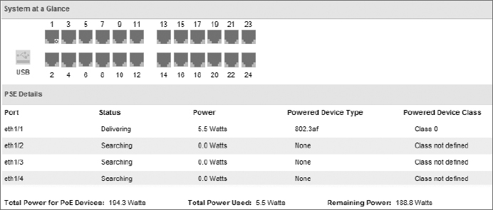
The power budget of a switch or multiple switches should be monitored to make sure that all devices can maintain power. PSE active budget information can usually be seen from the command line of a switch or the GUI interface or monitored by a centralized network management server (NMS). In the example shown in Figure 17.14, a switch has an overall budget of 194.3 watts. An access point is plugged into port 1 and is currently using 5.5 watts, which means 188.8 watts can still be used by other devices. In this example, the AP has been classified as a Class 0 device, which means it can draw as much as 12.95 watts. If an AP is not very busy, it may only need 5 or 6 watts, but if the AP has many clients connected with heavy traffic, the full 12.95 watts might be needed. Therefore, always plan your power budget based on the maximum draw that devices such as access points might use.
FIGURE 17.14 Power budget monitoring
Why Are My Access Points Randomly Rebooting?
WLAN vendors commonly receive support calls from customers complaining that all of a sudden access points randomly begin to reboot. In most cases, the root cause of random rebooting of APs is that the switch power budget has been eclipsed. Very often, if an AP cannot get the power that it needs, the AP will reboot and try again. Remember that other devices, such as desktop VoIP phones, also use PoE. An extra PoE-powered device might have been plugged into a switch port and the power budget has been exceeded. Proper power budgeting for access points and any other PoE-capable devices is paramount.
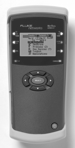
Because of the demand for PoE-enabled devices, some switch manufacturers have replaced their 110 volt/30 amp power supplies with 220 volt/20 amp power supplies. The manufacturers are also putting larger power supplies in their switches to handle the additional requirements of PoE. Some PoE switches support power supplies as large as 9,000 watts. As the demand for PoE devices increases, the need to manage and troubleshoot PoE problems will also increase. Test equipment, like that shown in Figure 17.15, can be placed between the PSE and the PD to troubleshoot PoE link issues.
The more PoE devices that you add to the network, the more you concentrate the power requirements in the data center or wiring closet. As your power needs increase, electrical circuits supplying power to the PoE switches might have to be increased. Also, as the power increases, you increase the amount of heat that is generated in the wiring closets, often requiring more climate-control equipment. When you are using high-wattage power supplies, we recommend that you also use redundant power supplies.
Redundancy
As children, we knew that even when there was an electrical failure, the telephone still worked and provided the ability to call someone. This is a level of service that we have come to expect. As VoIP and VoWiFi telephones replace traditional telephone systems, it is important to still provide this same level of continuous service. To achieve this, you should make sure that all of your PoE PSE equipment is connected to uninterruptible power sources. Additionally, it may be important enough to provide dual Ethernet connections to your PoE PD equipment.
FIGURE 17.15 Fluke NetTool Series II inline network tester
Be Careful with PoE
With the increase in popularity of PoE and the requirement to provide power to devices like APs and VoIP telephones, more PoE jacks are being deployed in the office space. One of the nice and necessary features of PoE is that when a device is plugged in, the PSE can determine whether the device is PoE capable and, if so, will provide power to that device. If the device is not PoE capable, then Ethernet without power will be provided to the device.
Depending on the brand and model of your PoE switch, when a PoE-enabled device is unplugged from the switch, it is possible for the port of the switch to maintain its PoE status for a few seconds, even though there is nothing plugged into the switch. If you were to quickly plug another device into the same port, it is possible for the PoE switch to provide power to that device, even if it is not a PoE-capable device. This introduces a risk of damage to the device.
To prevent this risk from occurring, after unplugging any Ethernet device, you should get into the habit of waiting 5 to 10 seconds before plugging another device into that port or jack. This 5- to10-second delay should be long enough for the PoE port to disable itself. Then when another device is plugged into that port, PoE will identify whether the new device is PoE capable.
802.11n or 802.11ac and PoE
In Chapter 18, “802.11n,” you will learn that most current enterprise 802.11n APs use 2x2:2 or 3x3:3 MIMO radios and are dual-frequency capable. In other words, a 3x3:3 dual-frequency 802.11n AP has a total of six radio chains, or transmitters that require power. Power is needed for the three 2.4 GHz transmit chains as well as for the three 5 GHz transmit chains. When the first-generation of 802.11n access points debuted, in many cases, 12.95 watts was insufficient to power a dual-frequency MIMO AP with six transmit radio chains. Some of these multi-radio APs might have needed as much as 20 watts of power.
The first generation of 802.11n APs could be powered sufficiently with 802.3at switches, but most customers still owned 802.3af switches that were only capable of 15.4 watts of power per port. Therefore, many of the WLAN vendors devised various techniques so that the first generation of 802.11n APs could operate using the lower 802.3af power. However, the trade-off was downgraded performance of the first-generation 802.11n APs that operated with 802.3af PSE equipment. The most common method was to downgrade the MIMO capability of the 802.11n access points so that 802.3af power could be used. 802.11n APs with 3x3:3 transmitter capability might only use a single transmitter when using 802.3af PoE and therefore conserve power. The downside was that not all of the MIMO transmitter capabilities were being used by the APs.
The good news is that almost all of the current generation of 3x3:3 dual-frequency 802.11n APs are indeed capable of running with full transmitter capabilities using 802.3af PoE. The 802.11n AP power consumption is lighter and better controlled with the newer hardware that is now available. However, the six transmit radio chains still require more than the 12.95 watts maximum draw that is defined by the 802.3af standard. The MIMO APs may draw as much as 15 watts from PSE that is capable of 15.4 watts. The WLAN vendors are squeezing a little extra power draw from the PSE. Category 5e or higher cabling is required for an AP to get the extra power draw. Category 3 cabling will not work.
In Chapter 19, “Very High Throughput (VHT) and 802.11ac,” you will learn that the 802.11ac radios operate on the 5 GHz band; however, the 2.4 GHz radios still use 802.11n technology. The 802.11ac radios use more complex modulation and can provide for the use of 80 MHz or larger channels at 5 GHz. These new 802.11ac mechanisms require more processing resources and therefore require more power. So, the first generation of 802.11ac 3x3:3 APs require more power than 802.3af can provide and 802.3at power is needed for some of the 802.11ac radios to be fully operational. Some WLAN vendors have released their first-generation 802.11ac access points and 802.3af is fully supported. History has repeated itself, and many of the WLAN vendors have devised various techniques so that the first generation of 802.11ac APs can operate using the lower 802.3af power. However, the trade-off is downgraded performance of the first-generation 802.11ac APs that operate in an 802.3af mode. Once again, the most common method is to downgrade the MIMO capability of the 802.11ac access points so that 802.3af power can be used. 802.11ac APs with 3x3:3 transmitter capability might only use one or two transmitters when using 802.3af PoE and therefore conserve power. The downside is that not all of the MIMO transmitter capabilities are being used by the APs. Other vendors have chosen to disable processor-intensive 802.11ac functions, such as 80 MHz channel capability and the use of more complex modulation. In other words, the 802.11ac 3x3:3 MIMO radio can still use all three transmitters, but effectively the radio functions as an 802.11n radio when using the lower 802.3af power. The good news is that several WLAN vendors now offer 3x3:3 802.11ac access points that are fully functional with 802.3af power.
A second wave of 802.11ac access points is appearing. The next generation of 802.11ac hardware will use a new chipset that enables beamforming capabilities, which will require more processing resources and therefore more power. Most likely the second wave of 802.11ac access points will also use 4x4:4 MIMO radios, which also will require more power. As we move toward the next generation of MIMO access points, the use of 802.3at power will most likely be a requirement.
There is no reason you cannot use an available power outlet to provide electrical current to an AP. The downside is that most APs are deployed in areas where a power outlet is not conveniently accessible. The best way to power 802.11n and 802.11ac APs is to deploy a PoE+ (802.3at) PSE that is capable of providing 30 watts via an Ethernet cable. With the fast growth of wireless, if you are purchasing PoE switches, you should only consider switches that are 802.3at (PoE+) capable.
Summary
This chapter focused on Power over Ethernet and the equipment and techniques necessary to provide service to PDs. Power over Ethernet can be provided in two general ways: through proprietary PoE or through standards-based PoE (802.3af or 802.3at, integrated into the IEEE Std 802.3 in Clause 33).
Standards-based PoE consists of a few key components:
- Powered device (PD)
- Power-sourcing equipment (PSE)
- Endpoint PSE
- Midspan PSE
These components work together to provide a functioning PoE environment.
The final section of this chapter covered considerations that need to be made when planning and deploying PoE:
- Power planning
- Redundancy
Exam Essentials
Know the history of PoE. Make sure you know the history of PoE, the original 802.3af amendment, the 802.3at amendment, and current references to IEEE Std 802.3, Clause 33.
Be familiar with the various PoE devices and how they interoperate. Make sure you know about the various PoE devices and their roles in providing PoE. Understand how the following devices work: powered device (PD), power-sourcing equipment (PSE), endpoint PSE, and midspan PSE.
Know the different device classes and the classification process. Make sure you know the five device classes and how the classification process works to determine the class of a PD. Know how much current each class of devices uses along with how much power the PSE generates for each class of devices.
Review Questions
- The IEEE 802.3af and 802.3at amendments have been incorporated into the IEEE Std 802.3 revised standard and are defined in which clause?
- Clause 15
- Clause 17
- Clause 19
- Clause 33
- Clause 43
- If a classification signature is not provided, the device is considered to be in what class?
- 0
- 1
- 2
- 3
- 4
- Which types of PoE devices are defined by the standard? (Choose all that apply.)
- PSE
- PPE
- PD
- PT
- A powered device (PD) must be capable of accepting up to how many volts from either the data lines or the unused pairs of the Ethernet cable?
- 14.5 volts
- 20.5 volts
- 48 volts
- 57 volts
- To qualify as compliant with the 802.3at amendment (now part of the 802.3 standard), a powered device (PD) must do which of the following? (Choose all that apply.)
- Be able to accept power over the unused data pairs.
- Reply to the PSE with a detection signature.
- Accept power with either polarity from the PSE.
- Reply to the PSE with a classification signature.
- A VoIP telephone is connected to a 24-port PoE midspan PSE. If the telephone does not provide a classification signature, how much power will the PSE provide to the telephone?
- An endpoint PSE that provides power by using Alternative B is capable of providing power to devices by using which of the following Ethernet technologies? (Choose all that apply.)
- 10BaseT
- 100BaseTX
- 1000BaseT
- 100BaseFX
- What is the range of maximum power used by a class 4 PD?
- 0.44 to 12.95 watts
- 3.84 to 6.49 watts
- 6.49 to 12.95 watts
- 12.95 to 25.5 watts
- 15 to 30 watts
- At maximum power requirements, a 24-port 802.3at-compliant PoE Ethernet switch must be able to provide about how many total watts of power to PoE devices on all ports?
- 15.4 watts
- 370 watts
- 720 watts
- 1,000 watts
- Not enough information is provided to answer the question.
- If an 802.3at-compliant AP is equipped with two radios and requires 7.5 watts of power, how much power will the PSE provide to it?
- 7.5 watts
- 10.1 watts
- 15 watts
- 15.4 watts
- 30.0 watts
- The PSE provides power within a range of_____volts, with a nominal value of_____volts.
- 14.5 to 20.5, 18
- 6.49 to 12.95, 10.1
- 12 to 19, 15.4
- 44 to 57, 48
- Tim has installed an Ethernet switch that is compliant with 802.3at. He is having problems with his APs randomly rebooting. Which of the following could be causing his problems?
- You are designing an 802.3at-compliant network and are installing a 24-port Ethernet switch to support 10 Class 1 VoIP phones and 10 Class 0 APs. The switch requires 500 watts to perform its basic switching functions. How much total power will be needed?
- 500 watts
- 694 watts
- 808 watts
- 1,000 watts
- You are designing an 802.3at-capable network and are installing a 24-port Ethernet switch to support 10 Class 2 cameras and 10 Class 3 APs. The switch requires 1,000 watts to perform its basic switching functions. How much total power will be needed?
- 1,080 watts
- 1,224 watts
- 1,308 watts
- 1,500 watts
- When a PoE network is installed, what is the maximum distance from the PSE to the PD, as defined in the standards? (Choose all that apply.)
- 90 meters
- 100 meters
- 300 feet
- 328 feet
- 328 meters
- What is the maximum power draw of an 802.3at PD?
- 12.95 watts
- 15 watts
- 7.4 watts
- 25.5 watts
- 30 watts
- What is the maximum power used by a PD Class 0 device?
- 3.84 W
- 6.49 W
- 12.95 W
- 15.4 W
- The PSE will apply a voltage of between 14.5 and 20.5 and measure the resulting current to determine the class of the device. Which current range represents Class 2 devices?
- 0 to 4 mA
- 5 to 8 mA
- 9 to 12 mA
- 13 to 16 mA
- 17 to 20 mA
- A PD must be capable of accepting power with either polarity from the power supply. In mode A, on which conductors/wires does the PD accept power?
- 1, 2, 3, 4
- 5, 6, 7, 8
- 1, 2, 3, 6
- 4, 5, 7, 8
- A Type 2 PSE will perform a two-event Physical layer classification or Data-Link layer classification. If mutual identification cannot be completed, what does the Type 2 device do?
- Defaults as a Category 0 device.
- PoE cannot be enabled.
- Operates as a Type 1 device.
- Provides 15.4 watts of power using Alternative A.