
7
Demystifying Kubernetes Networking
This chapter will use the Kubernetes networking model to describe some core concepts, as well as how to configure Kubernetes networking on the cluster nodes and network policies. We will also learn about how to configure Ingress controllers and Ingress resources, how to configure and leverage CoreDNS, and how to choose an appropriate container network interface plugin. This content covered in this chapter makes up about 20% of the CKA exam.
In this chapter, we’re going to cover the following topics:
- Understanding the Kubernetes networking model
- Configuring Kubernetes networking on the cluster nodes
- Configuring network policies
- Configuring Ingress controllers and Ingress resources
- Configuring and leveraging CoreDNS
- Choosing an appropriate container network interface plugin
Technical requirements
To get started, we need to make sure your local machine meets the following technical requirements:
- A compatible Linux host. We recommend a Debian-based Linux distribution such as Ubuntu 18.04 or later.
- Make sure your host machine has at least 2 GB RAM, 2 CPU cores, and about 20 GB of free disk space.
Understanding the Kubernetes networking model
Kubernetes is designed to facilitate the desired state management to host containerized workloads – these workloads take advantage of sharable compute resources. Kubernetes networking resolves the challenge of how to allow different Kubernetes components to communicate with each other and applications on Kubernetes to communicate with other applications, as well as the services outside of the Kubernetes cluster.
Hence, the official documentation summarizes those networking challenges as container-to-container, pod-to-pod, pod-to-service, external-to-service, and node-to-node communications. Now, we are going to break them down one-by-one in this section.
Container-to-container communication
Container-to-container communication mainly refers to the communication between containers inside a pod – a multi-container pod is a good example of this. A multi-container pod is a pod that contains multiple containers and is seen as a single unit. Within a pod, every container shares the networking, which includes the IP address and network ports so that those containers can communicate with one another through localhost or standard inter-process communications (IPC) such as SystemV semaphores or POSIX shared memory. All listening ports are accessible to other containers in the pod even if they’re not exposed outside the pod.
The following figure shows how those containers share a local network with each other inside the same pod:

Figure 7.1 – Multiple containers sharing the pod networking
The following is an example called multi-container-pod.yaml that shows how to create multi-containers in a pod. In this pod, it contains nginx and busybox – two containers where busybox is a sidecar container that calls nginx through port 80 on localhost:
apiVersion: v1kind: Podmetadata: name: multi-container-pod labels: app: multi-containerspec: containers: - name: nginx image: nginx:latest ports: - containerPort: 80 - name: busybox-sidecar image: busybox:latest command: ['sh', '-c', 'while true; do sleep 3600; done;']Let’s deploy this yaml file by using the kubectl apply -f multi-container-pod.yaml command, and the following shows the pod has been created:
pod/multi-container-pod created
We can use the following command to check whether we could talk to the nginx container from the sidecar busybox container:
kubectl exec multi-container-pod -c busybox-sidecar -- wget http://localhost:80
The following output proves that both containers can talk to each other:

Figure 7.2 – Connecting to the nginx container from the busybox sidecar
Important Note
A quicker way to create a single container pod by command is by using the following command:
kubectl run nginx --image=nginx:latest --port=80
Then, you can use the kubectl get pods –o yaml command to export the YAML content, and edit the yaml file to add another container.
To double-check that we did indeed get the nginx main page from the busybox sidecar container, we will use the following command:
kubectl exec multi-container-pod -c busybox-sidecar -- cat index.html
The output should look similar to what is shown in Figure 7.3:
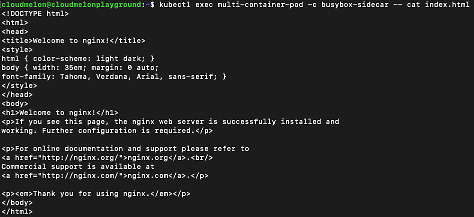
Figure 7.3 – Checking out the downloaded html page in the busybox container
To learn more about multi-container pods to see how those containers share storage and networking, refer to Chapter 4, Application Scheduling and Lifecycle Management.
Pod-to-pod communication
In Kubernetes, each pod has been given a unique IP address based on the podCIDR range of that worker node. Although this IP assignment is not permanent, as the pod eventually fails or restarts, the new pod will be assigned a new IP address. By default, pods can communicate with all pods on all nodes through pod networking without setting up Network Address Translation (NAT). This is also where we set up host networking. All pods can communicate with each other without NAT.
Let’s deploy a nginx pod by using the following command:
kubectl run nginx --image=nginx –-port=8080
The following output shows the pod has been created:
pod/nginx created
To verify whether the pod has been assigned an IP address, you can use the kubectl get pod nginx -o wide command to check the IP address of the nginx pod. The output is similar to the following:
NAME READY STATUS RESTARTS AGE IP
NODE NOMINATED NODE READINESS GATES
nginx 1/1 running 0 34s 172.17.0.4
minikube <none> <none>
You can use the following command to check all pods available in the default namespace and their assigned IP addresses:
k get pods -o wide
Notice the IP column in the following output – it indicates an IP address of 172.17.0.3 for the multi-container-pod pod and 172.17.0.4 for the nginx pod. These IP addresses assigned to those pods are in the same podCIDR:

Figure 7.4 – Checking out the IP addresses of the pods
The preceding screenshot also indicates that both pods are on the same node, minikube, according to the NODE column. We could check the podCIDR assigned to the pod by using the following command:
kubectl get node minikube -o json | jq .spec.podCIDR
The output, which looks as follows, shows the podCIDR:
10.244.0.0/24
From the preceding command output, we can see it does not have the same CIDR as the pods. That’s because we tested on a minikube cluster. When we start a vanilla minikube installation with the minikube start command without specifying additional parameters for the CNI network plugin, it sets the default value as auto. It chooses a kindnet plugin to use, which creates a bridge and then adds the host and the container to it. We’ll get to know how to set up a CNI plugin and network policy later in this chapter. To get to know more about kindnet, visit the following link: https://github.com/aojea/kindnet.
Kubernetes components such as system daemons and kubelet can communicate with all pods on the same node. Understanding the connectivity between pods is required for the CKA exam. You can check out the official documentation about cluster networking if you want to learn more here: https://kubernetes.io/docs/concepts/cluster-administration/networking/#the-kubernetes-network-model.
Pod-to-service and external-to-service communications
Effective communication between pods and services entails letting the service expose an application running on a set of pods. The service accepts traffic from both inside and outside of the cluster. The set of pods can load - balance across them – each pod is assigned its own IP address and a single DNS.
Similar to pod-to-service, the challenge with external-to-service communication challenge is also resolved by the service. Service types such as a NodePort or a LoadBalancer can receive traffic from outside the Kubernetes cluster.
Let’s now take a look at different service types and endpoints.
An overview of Kubernetes service types
There are a few types of publishing services in the Kubernetes networking space that are very important. This is different from a headless service. You can visit this link if you want to learn about headless services, which is out of the scope of the CKA exam: https://kubernetes.io/docs/concepts/services-networking/service/#headless-services.
The following are the most important types of publishing services that frequently appear in the CKA exam:
|
Service type |
Description |
Example |
|
ClusterIP |
A default service type for Kubernetes. For internal communications, exposing the service makes it reachable within the cluster. |
Checking out the pod address by using the kubectl get pod mypod -o wide – the internal IP is 172.17.0.4 |
|
NodePort |
For both internal and external communication. NodePort exposes the service on a static port on each worker node – meanwhile, a ClusterIP is created for it, and it is used for internal communication, requesting the IP address of the node with an open port – for example, <nodeIP>:<port> for external communication. |
Connecting to a worker node VM with the public IP address 192.0.2.0 from port 80 |
|
LoadBalancer |
This works for cloud providers, as it’s backed by their respective load balancer offerings. Underneath LoadBalancer, ClusterIP and NodePort are created, which are used for internal and external communication. |
Checking out the services for a Kubernetes distribution from a cloud provider such as Azure Kubernetes Service (AKS) or Google Kubernetes Engine (GKE) by using kubectl get service mysvc -n mynamespace – the internal IP is 172.17.0.4 |
|
ExternalName |
Maps the service to the contents with a CNAME record with its value. It allows external traffic access through it. |
For example, my.packt.example.com |
To learn more about the differences between publishing services and headless services, check here: https://kubernetes.io/docs/concepts/services-networking/service/#publishing-services-service-types. Now, let’s take a look at each of those services in this section.
ClusterIP
ClusterIP is the default Kubernetes service type for internal communications. In the case of a pod or ClusterIP, the pod is reachable inside the Kubernetes cluster. However, it is still possible to allow external traffic to access the ClusterIP via kube-proxy, which creates iptables entries. It comes in handy in some use cases, such as displaying Kubernetes dashboards. Figure 7.5 describes how the network traffic load - balances (round-robin) and routes to the pod. Then, it goes through ClusterIP or other services before hitting the pods:
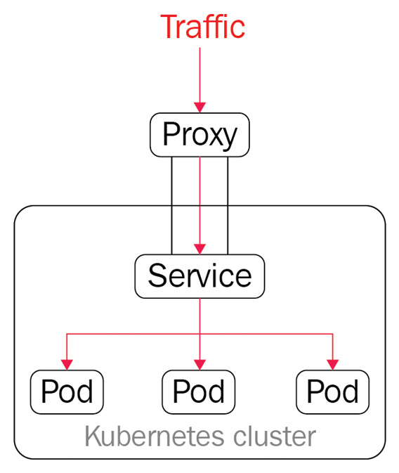
Figure 7.5 – ClusterIP and kube-proxy
Through the preceding diagram, we get a first look at how the service works with the pods. Let’s go ahead and deploy an application and do a deeper dive. To create a deployment called nginx and with the replicas number of 2, use the following command:
kubectl create deployment nginx --image=nginx --replicas=2
We can track down the process of deployment by the following command:
kubectl get deploy nginx -o wide
Once we do, we should be able to see the following output:
Figure 7.6 – The available nginx replica counts
From the preceding output, we can see that two copies of the nginx pod are up and running, just to get a better understanding of those pods. We can see how those nginx pods are presented in the default namespace.
Note that we’re doing the test in the default namespace for simplicity. You can add the -n flag to work with deployment and pods in a different namespace. Refer to Chapter 4, Application Scheduling and Lifecycle Management, to see how the application deployment in Kubernetes works. Go and try the following command:
kubectl get pods
The output will return all the available pods in the default namespace:

Figure 7.7 – The available nginx pods in the default namespace
Now, we’re exposing these pods to the Kubernetes cluster. We’re using the following command to create a service called melon-service:
kubectl expose deployment nginx --type=ClusterIP --port 8080 --name=melon-service --target-port 80
From the preceding command, we can see that we have created a ClusterIP type of service. We can specify the following flags:
- type is the type of service – in our case, it is ClusterIP. We’ll take a look at NodePort and LoadBalancer in the next sections of this chapter.
- port is the port that the service serves on.
- target-port is the port on the container to which the service redirects the traffic.
Important Note
Understanding those command flags will help you use them smoothly; I recommend remembering this command so that you can quickly recall it during the actual CKA exam. You can also refer to the following link (https://kubernetes.io/docs/reference/generated/kubectl/kubectl-commands#expose) to understand whether other flags will help you along the way.
The output of the previous command should look similar to the following:
service/melon-service exposed
The preceding command is executed successfully based on this output. Now, let’s go to the default namespace and check out all the available services using the kubectl get svc command – this will give you the following output:

Figure 7.8 – The available nginx pods in the default namespace
The preceding output shows the ClusterIP type has been created with an IP address of 10.102.194.57 and this service serves on a port of 8080.
What we did in this section to create a new ClusterIP service by using the kubectl expose command can also be done using the following YAML manifest file:
apiVersion: v1 kind: Service metadata: name: melon-service spec: type: ClusterIP selector: app: nginx ports: - protocol: TCP port: 8080 targetPort: 80From the preceding YAML definition, we can see there’s a section called selector. This section has a key-value pair, app:nginx, that has a label sector. Usually, we use a selector to map the service with the pods. Here’s the YAML definition of the nginx deployment if we didn’t go for the kubectl command:
apiVersion: apps/v1kind: Deploymentmetadata: name: nginxspec: selector: matchLabels: app: nginx replicas: 2 template: metadata: labels: app: nginx spec: containers: - name: nginx image: nginx ports: - containerPort: 80From the preceding YAML definition, we can see that there is a section to specify the selector and we used the same key-value pair, app: nginx, to map the ClusterIP specification so that it worked as expected. Refer to Chapter 4, Application Scheduling and Lifecycle Management, to learn more about label sectors.
Important Note
As we mentioned before, the CKA exam is about time management, so it will be much more efficient to use commands to achieve the goal.
A corresponding endpoints object can achieve what we have discussed without using a selector. You can use the following commands to get the endpoints of melon-service:
k get ep melon-service
The following is the output of the preceding command:
Figure 7.9 – Display the endpoints of the nginx pods in the default namespace
As you can see, there’s nothing specific in the YAML definition file that we defined here. We can compare the service definition by exporting its YAML definition using the following command:
kubectl get svc melon-service -o yaml
We will be able to see the exported output as follows:

Figure 7.10 – The definition of the nginx service in the default namespace
Comparing this exported definition with what we have walked through in this section using kubectl and a YAML definition will help you understand the services in Kubernetes better. Now, let’s take a look at another important service in Kubernetes, called NodePort.
NodePort
NodePort opens ports on the Kubernetes nodes, which usually are de facto virtual machines. NodePort exposes access through the IP of the nodes and, with the opened port, makes the application accessible from outside of the Kubernetes cluster. The network traffic is forwarded from the ports to the service. kube-proxy allocates a port in the range 30000 to 32767 on every node – it works as shown in the following figure:
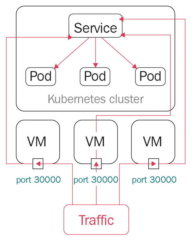
Figure 7.11 – A NodePort in Kubernetes
With the preceding diagram, we get a closer look at how NodePort works with the pods. Let’s go ahead and create a deployment called webfront-app with a replicas number of 2 using the following command:
kubectl create deployment webfront-app --image=nginx --replicas=2
If it’s created successfully, you will see the following output:
deployment.apps/webfront-app created
Then, we can go ahead and use the following command to expose a web frontend using NodePort:
kubectl expose deployment webfront-app --port=8080 --target-port=80 --type=NodePort
The following output shows that we have exposed webfront-app successfully:
service/webfront-app exposed
Note that if you don’t provide a target port, it is assumed to be the same as the container port. Also note that if you don’t provide a node port, a free port in the range between 30000 and 32767 is automatically allocated.
Now, let’s check all the services that we have just created. As we didn’t specify the name in the previous command, the service name is presumed to be the same as the application name:
kubectl get svc webfront-app -o wide
The output should look as follows:
Figure 7.12 – The webfront-app NodePort in the default namespace
From the preceding output, we can see the port is exposed at 31400, which is in the range of 30000 to 32767 on the node, and the target port is 80, which is opened at the container level. So, let’s get the node IP by using the following command:
kubectl get node -o wide
The key part of your output is as follows:
Figure 7.13 – The internal IP of the webfront-app NodePort
From the preceding output, we are getting the internal IP of the node, as we’re testing locally, so we can use the internal IP and port in conjunction to connect to webfront-app:
192.168.65.4:31400
Let’s deploy a new nginx pod called sandbox-nginx to test out the connectivity by using the following command:
kubectl run -it sandbox --image=nginx --rm --restart=Never -- curl -Is http://192.168.65.4:31400
The output is similar to the following:
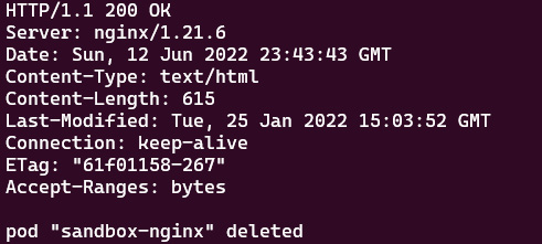
Figure 7.14 – The internal IP of the webfront-app NodePort
In the actual CKA exam, you’ll be working on a few different VMs. In case you need to connect to the application deployed on that node, you can use the following command to get the external IPs of all nodes:
kubectl get nodes -o jsonpath='{.items[*].status.addresses[?( @.type=="ExternalIP")].address}'
Similarly, if you want to get the internal IPs of all nodes, you can use the following command:
kubectl get nodes -o jsonpath='{.items[*].status.addresses[?( @.type==" InternalIP ")].address}'
In the actual exam, you can also connect to that node using the internal IP, and then use the following command, which will give you the same result:
curl -Is http://192.168.65.4:31400
In the case that you have a public IP address of the node VM that you can ping from your local environment, you can use the following command:
curl -Is http://<node external IP>:<node port>
Tips and Tricks
Some important JSONPath commands can be found on the Kubernetes cheat sheets here if you need some help: https://kubernetes.io/docs/reference/kubectl/cheatsheet/#viewing-finding-resources.
What we did in this section to create a new NodePort service by using the kubectl expose command can also be done using the following YAML manifest file:
apiVersion: v1kind: Servicemetadata: name: webfront-app labels: app: webfront-appspec: ports: - port: 8080 targetPort: 80 selector: app: webfrontapp type: NodePortPublic cloud providers often support an external load balancer, which we can define as LoadBalancer when working with Kubernetes. Now, let’s take a look at it in the following section.
LoadBalancer
LoadBalancer is a standard way to connect a service from outside of the cluster. In this case, a network load balancer redirects all external traffic to a service, as shown in the following figure, and each service gets its own IP address. It allows the service to load - balance the network traffic across applications:
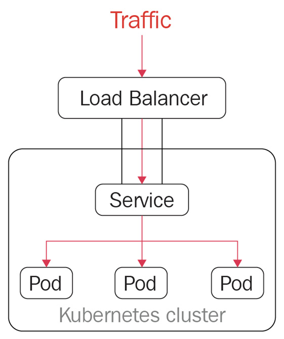
Figure 7.15 – LoadBalancer in Kubernetes
LoadBalancer is not a popular topic in the CKA exam, as it only works in a cloud environment or another environment that supports external load balancers. Deploying the LoadBalancer service to get a public IP is commonly used in managed Kubernetes distributions such as Azure Kubernetes Service (AKS), Elastic Kubernetes Service (EKS), and Google Kubernetes Engine (GKE). LoadBalancer is the default outbound type for AKS – the following is a sample YAML definition in that regard:
apiVersion: v1kind: Servicemetadata: name: packt-svcspec: type: LoadBalancer ports: - port: 80 targetPort: 8080 selector: app: my-packt-appWe could also use the kubectl expose command to do so:
kubectl expose deployment nginx --port=80 --target-port=8080
--name=packt-svc --type=LoadBalancer
The output of the preceding command is as follows:
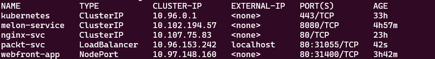
Figure 7.16 – LoadBalancer output in Kubernetes
Since I was testing LoadBalancer in Docker Desktop with WSL2, it was not supported – the preceding output shows that EXTERNAL-IP is localhost. Although, when I was working on AKS, it showed the real public IP address. Refer to this link to see what worked out for me: https://docs.microsoft.com/en-us/azure/aks/load-balancer-standard.
ExternalName
ExternalName maps the service to the contents with a CNAME record with its value. It allows external traffic to access it. The following is the sample YAML definition for ExternalName:
apiVersion: v1kind: Servicemetadata: name: my-packt-svc namespace: prodspec: type: ExternalName externalName: my.melonapp.packt.comNote that the preceding ExternalName type is defined as my.melonapp.packt.com – we could use the nslookup command to check my-packt-svc.default,svc.cluster.local. This returns the CNAME record for my.melonapp.packt.com. We’ll dive deeper into how the DNS in Kubernetes works later in this chapter.
Check services and endpoints
In this section, we have worked on all four of the common service types in Kubernetes. In case we need to quickly check all the services across all namespaces, we can use the following command:
kubectl get services --all-namespaces
Alternatively, we can use the following command:
kubectl get svcs -A
The following shows the output for the preceding command:
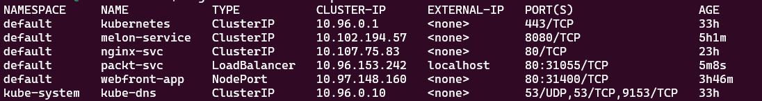
Figure 7.17 – Getting all the services across different namespaces
The preceding screenshot lists services across namespaces, as well as their ClusterIP and port information. If you want to check out a specific service, you can use the following:
kubectl get svc <service-name> -n <namespace>
The example of the preceding command is kubectl get svc kube-dns -n kube-system, which will give you the service information. You can also go one step further to check the details by using the kubectl describe svc command:
kubectl describe svc kube-dns -n kube-system
The output of the preceding command is as follows:

Figure 7.18 – Checking the service details
For the endpoints, we can use the following command to check the endpoint of the service:
kubectl get endpoints melon-service
It can also be as follows:
NAME ENDPOINTS AGE
melon-service 10.1.0.32:80,10.1.0.33:80 5h7m
In case we’d like to check out all the endpoints across the different namespaces, we have the following:
kubectl get ep --all-namespaces
The output of the preceding command will list all the endpoints across different namespaces:

Figure 7.19 – Getting all the endpoints across different namespaces
The same principle also applies to listing all the endpoints by namespace. When you want to check out a specific service, you can use the following:
kubectl get ep <service-name> -n <namespace>
We have talked about how to work with services and endpoints in Kubernetes, which covers pod-to-service communication. Now, let’s get into node-to-node communication in the next section.
Node-to-node communication
Within a cluster, each node is registered by the kubelet agent to the master node, and each node is assigned a node IP address so they can communicate with each other.
To verify this, you can use the kubectl get node -o wide command to check the internal IP of each node. The output is similar to the following, in which you’ll notice an internal-IP for the worker node:

Figure 7.20 – Checking out the node IP and further information
From the preceding screenshot, we can see the internal IP of the current node is 192.168.49.2. In the case that we have multiple nodes, we can ping each node from the node within the same network. We need to ensure the connectivity between master nodes and worker nodes, so the workloads get to be scheduled to the worker node. In this regard, a good understanding of how to configure the hosting network for Kubernetes nodes is very important. So, let’s have a look at the container network interface plugin next.
Choosing an appropriate Container Network Interface plugin
In Chapter 2, Installing and Configuring Kubernetes Clusters, we talked about how to use the Calico plugin as the overlay network for our Kubernetes cluster. We can enable the Container Network Interface (CNI) for pod-to-pod communication. The CNI plugins conform to the CNI specification. Once the CNI is set up on the Kubernetes cluster, it will allocate the IP address per pod.
CNI networking in Kubernetes
There’s a wide range of networking plugins working with Kubernetes on today’s market, including popular open source frameworks such as Calico, Flannel, Weave Net, and more. For more options, check out the official documentation here: https://kubernetes.io/docs/concepts/cluster-administration/addons/.
Taking Flannel as an example, Flannel is focused on configuring a Layer 3 network fabric designed for Kubernetes, mainly for routing packets among different containers. Flannel runs a single binary agent called flanneld on each host, which is responsible for allocating a subnet preconfigured address space to each host, as in the following:
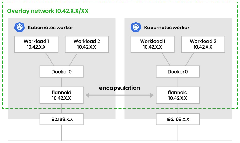
Figure 7.21 – CNI networking in Kubernetes
The preceding figure demonstrates how Flannel CNI networking works. There are many options in the community – let’s take a look at the decision metrics about choosing the CNI plugin.
Decision metrics
To make a good choice of an appropriate CNI plugin that fits your requirements, you can refer to the following table of different features from each of the CNI providers mentioned:
|
Provider networking |
Encapsulation and routing |
Support for network policies |
Datastore |
Encryption |
Ingress / Egress | |
|
Flannel |
Layer 3 |
VxLAN |
No |
ETCD |
Yes |
No |
|
Calico |
Layer 3 |
BGP, eBPF |
Yes |
ETCD |
Yes |
Yes |
|
Weavenet |
Layer 2 |
VxLAN |
Yes |
NO |
Yes |
Yes |
|
Canal |
Layer 2 |
VxLAN |
Yes |
ETCD |
No |
Yes |
For quick testing, Flannel is simple to set up. Calico and Weave Net are better options for enterprise-grade customers, as they have a wide range of capabilities. In real life, it is possible to use multiple CNI solutions in a single environment to fulfill some complex networking requirements. However, that’s out of reach of the CKA certification exam.
Now let’s take a look at the Ingress controller in the next section.
Configuring Ingress controllers and Ingress resources
One of the challenges of Kubernetes networking is about managing internal traffic, which is also known as east-west traffic, and external traffic, which is known as north-south traffic.
There are a few different ways of getting external traffic into a Kubernetes cluster. When it comes to Layer 7 networking, Ingress exposes HTTP and HTTPS at Layer 7 routes from outside the cluster to the services within the cluster.
How Ingress and an Ingress controller works
Ingress acts as a router to route traffic to services via an Ingress-managed load balancer – then, the service distributes the traffic to different pods. From that point of view, the same IP address can be used to expose multiple services. However, our application can become more complex, especially when we need to redirect the traffic to its subdomain or even a wild domain. Ingress is here to address these challenges.
Ingress works with an Ingress controller to evaluate the defined traffic rules and then determine how the traffic is being routed. The process works as shown in Figure 7.22:
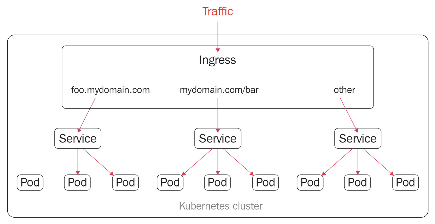
Figure 7.22 – Ingress resources in Kubernetes
In addition to what we see here in Figure 7.22, Ingress also provides some key capabilities such as load balancing, SSL termination, and name-based virtual hosting.
We need to deploy an Ingress controller in the Kubernetes cluster and then create Ingress resources. We are using ingress-nginx as an example in this section. We have a wide range of options for Ingress controllers on the market nowadays. Check out the official documentation here to get more details: https://kubernetes.io/docs/concepts/services-networking/ingress-controllers/.
Using multiple Ingress controllers
Note that it is also possible to deploy multiple Ingress controllers by using the Ingress class within a Kubernetes cluster. Refer to this article to get more details: https://kubernetes.io/docs/concepts/services-networking/ingress-controllers/#using-multiple-ingress-controllers.
Work with Ingress resources
As mentioned, the nginx Ingress controller is one of the most popular in today’s market, so we are using it as the main example in this section. We need to deploy an Ingress controller in the Kubernetes cluster and create Ingress resources.
Here, we are defining a minimal nginx resource with the following YAML definition:
apiVersion: networking.k8s.io/v1kind: Ingressmetadata: name: minimal-ingress annotations: nginx.ingress.kubernetes.io/rewrite-target: /spec: ingressClassName: packt-nginx rules: - http: paths: - path: /packs pathType: Prefix backend: service: name: test port: number: 80From the preceding YAML definition, we know that the apiVersion, kind, metadata, and spec fields are mandatory. Then, we also need an Ingress object, which contains a valid DNS subdomain name.
A default IngressClass would look as follows:
apiVersion: networking.k8s.io/v1kind: IngressClassmetadata: labels: app.kubernetes.io/component: controller name: nginx-example annotations: ingressclass.kubernetes.io/is-default-class: "true"spec: controller: k8s.io/ingress-nginxTo learn more about how to work with Ingress, check out the official documentation: https://kubernetes.io/docs/concepts/services-networking/ingress/.
Ingress annotations and rewrite-target
You can add Kubernetes annotations to specific Ingress objects so that you can customize their behaviors. These annotation keys and values can only be strings. The following is an example of how to add annotations to Ingress resources using nginx as an example:
apiVersion: networking.k8s.io/v1kind: Ingressmetadata: annotations: nginx.ingress.kubernetes.io/rewrite-target: / name: packt-ingressspec: ingressClassName: nginx rules: - host: book.packt.com http: paths: - path: /packt-book pathType: Prefix backend: service: name: packt-svc port: number: 80There are many annotations available for nginx – you can check them out by visiting the following page: https://kubernetes.github.io/ingress-nginx/user-guide/nginx-configuration/annotations/.
Different Ingress controllers provide different capabilities, often using annotations and rewrite-target to rewrite the default behavior. You can check out here to learn how to rewrite behaviors for nginx Ingress controllers: https://kubernetes.github.io/ingress-nginx/examples/rewrite/#rewrite-target.
We touched on the domain name and subdomain name in this section. Now, it’s a good time to talk about how the DNS domain hostname works in Kubernetes. Let’s get right into it in the next section:
Configuring and leveraging CoreDNS
As mentioned earlier in this chapter, nodes, pods, and services are assigned their own IP addresses in the Kubernetes cluster. Kubernetes runs a Domain Name System (DNS) server implementation that maps the name of the service to its IP address via DNS records. So, you can reach out to the services with a consistent DNS name instead of using its IP address. This comes in very handy in the context of microservices. All microservices running in the current Kubernetes cluster can reference the service name to communicate with each other.
The DNS server mainly supports the following three types of DNS records, which are also the most common ones:
- A or AAAA records for forward lookups that map a DNS name to an IP address. A record maps a DNS name to an IPv4 address, whereas an AAAA record allows mapping a DNS name to an IPv6 address.
- SRV records for port lookups so that connections are established between a service and a hostname.
- PTR records for reversing IP address lookups, which is the opposite function of A and AAAA records. It matches IP addresses to a DNS name. For example, a PTR record for an IP address of 172.0. 0.10 would be stored under the 10.0. 0.172.in-addr.arpa DNS zone.
Knowing these basic DNS concepts will help us get a better understanding of DNS in Kubernetes.
In Kubernetes 1.21, kubeadm removed support for kube-dns for DNS replication. CoreDNS is now becoming the default DNS service. CoreDNS is an extensible DNS server that can serve as a Kubernetes cluster DNS. It is a Cloud-Native Computing Foundation (CNCF) graduated project, as it’s stable and already has use cases running in a production environment successfully. You can check out the version of CoreDNS installed by kubeadm for Kubernetes in the past from here: https://github.com/coredns/deployment/blob/master/kubernetes/CoreDNS-k8s_version.md.
If your Kubernetes cluster is not on CoreDNS yet, here is an official end-to-end guide to help you migrate to CoreDNS smoothly and avoid backward - incompatible configuration issues: https://github.com/coredns/deployment/blob/master/kubernetes/Upgrading_CoreDNS.md.
Check whether the CoreDNS server is up and running
The Kubernetes DNS server schedules a DNS pod and service on the Kubernetes cluster to check whether the DNS server is up and running on your cluster. To do this, you can simply use the following command:
kubectl get pods -n kube-system
Normally, you should be able to see an output similar to the following:
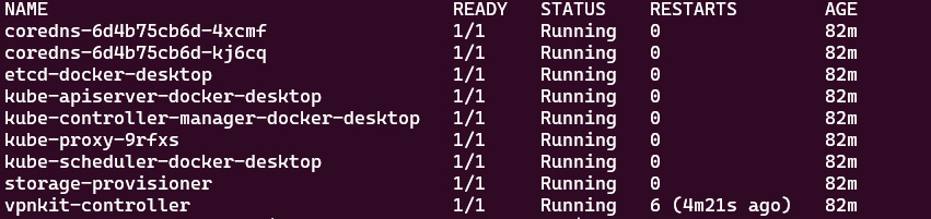
Figure 7.23 – When multi-container pods share a network
When you’re certain that you’re on CoreDNS, you can also use the following command:
kubectl get pods -n kube-system | grep coredns
The output is similar to the following:
coredns-6d4b75cb6d-4xcmf 1/1 Running 0 82m
coredns-6d4b75cb6d-kj6cq 1/1 Running 0 82m
From the previous output, you may have noticed that we have two replicas of the CoreDNS pod. The intention was to set the default value to two copies for high availability when installing CoreDNS. To prove this, you can check out the CoreDNS deployment settings by using the kubectl describe command as follows:
kubectl describe deploy coredns -n kube-system
The output should look similar to the following:

Figure 7.24 – When multi-container pods share a network
As it’s a deployment, we could use a typical kubectl scale command to scale the CoreDNS deployment out and in. This comes in handy when you want to economize some cluster resources. You can scale it down to one replica using the following command:
kubectl scale deploy coredns -n kube-system --replicas=1
The output should look as follows:
deployment.apps/coredns scaled
You can then use the kubectl get deploy command to check out the number of replicas currently available in the cluster:
NAME READY UP-TO-DATE AVAILABLE AGE
coredns 1/1 1 1 11h
Similarly, when you want it to be more resilient by scheduling more replicas, you can use the following command to get more replicas:
kubectl scale deploy coredns -n kube-system --replicas=4
Alternatively, we can go back to check the number of the replicas by using the following command:
kubectl get pods -n kube-system
As the following screenshot shows, we managed to increase the number of replicas of coredns from one to four:
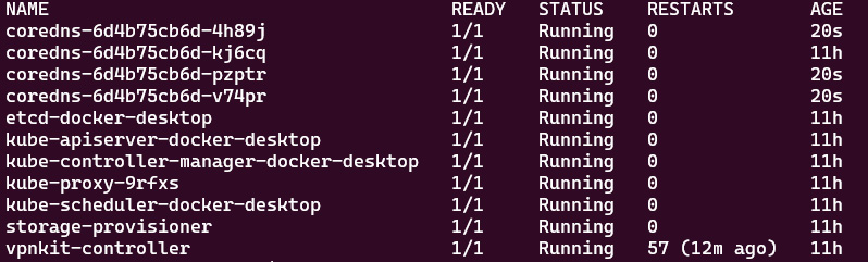
Figure 7.25 – When multi-container pods share a network
The previous examples also demonstrate that those four replicas of CoreDNS are identical. We can use the kubectl describe command to take a closer look at either of those four coredns pods. The following command is an example:
k describe pod coredns-6d4b75cb6d-4h89j -n kube-system
The output should look as follows:
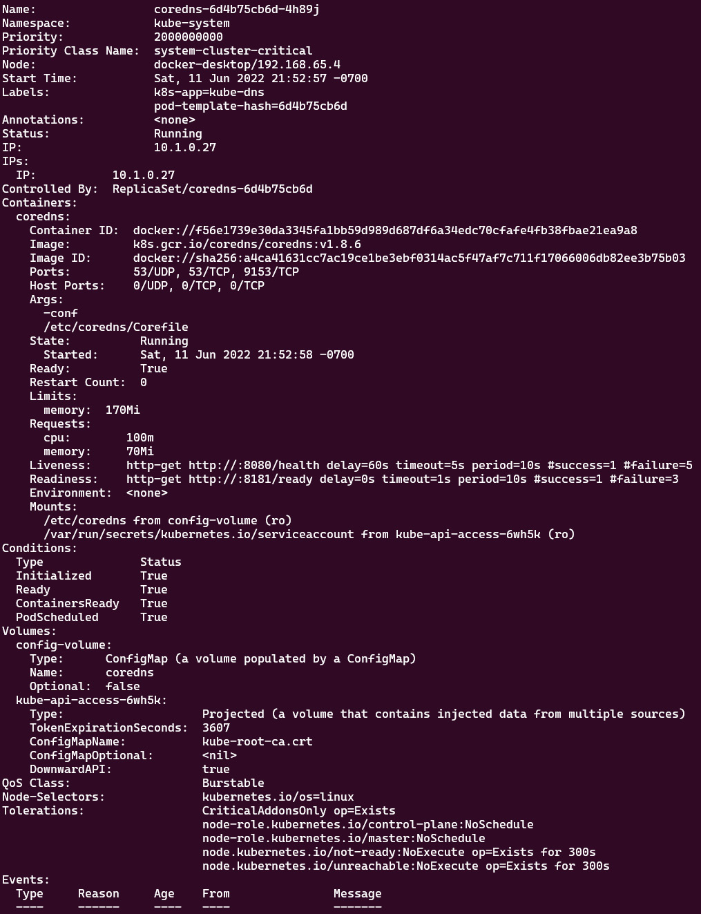
Figure 7.26 – When multi-container pods share a network
From the preceding output, we can see CoreDNS using Corefile for configurations. It is located in the following location:
/etc/coredns/Corefile
We can use the kubectl get configmaps command to inspect the content of Corefile. Here’s how it can be done:
kubectl get configmaps -n kube-system
The output should be as follows:

Figure 7.27 – When multi-container pods share a network
The preceding command shows there is configmap named coredns, so let’s use the kubectl describe configmap command to check out its content:
k describe configmap coredns -n kube-system
The following output will show how Corefile looks:
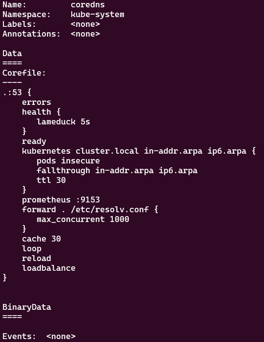
Figure 7.28 – Corefile for CoreDNS
Corefile is very useful when you need to customize the DNS resolution process in your Kubernetes cluster. Check out the official documentation about customizing the DNS service here: https://kubernetes.io/docs/tasks/administer-cluster/dns-custom-nameservers/#coredns-configmap-options.
Note that the Kubernetes DNS service is registered to the kubelet agent, so the Pods running on the cluster use the DNS server’s IP address to resolve the DNS names. kubelet sets the /etc/resolv.conf file for each pod – a DNS query for a myapp pod from the my-packt-apps namespace can be resolved using either myapp.my-packt-apps or myapp.my-packt-apps.svc.cluster.local. Now, let’s take a closer look at how the DNS hostname works for a pod in a Kubernetes cluster.
Pod IPs and DNS hostnames
Kubernetes creates DNS records for pods. You can contact a pod with fully qualified, consistent DNS hostnames instead of its IP address. For a pod in Kubernetes, the DNS name follows this pattern:
<your-pod-ip-address>.<namespace-name>.pod.cluster.local
Let’s deploy a pod named nginx using the following command:
kubectl run nginx --image=nginx –-port=8080
We’ll see that the pod has been deployed successfully if you have an output similar to the following:
NAME READY STATUS RESTARTS AGE
nginx 1/1 Running 0 3s
Let’s take a closer look at this pod:
kubectl get pod nginx -o wide
The output should look as follows:
Figure 7.29 – When a multi-container pod shares a network
From the figure, we know the IP address for the nginx pod is 10.1.0.9 within the cluster. From the preceding pattern, we could assume that the DNS name of this pod would look as follows:
10-1-0-9.default.pod.cluster.local
Important Note
Note that in practice, each pod in a StatefulSet derives the hostname from the StatefulSet name. The name domain managed by this service follows this pattern:
$(service name).$(namespace).svc.cluster.local
Check out the official documentation to know more: https://kubernetes.io/docs/concepts/workloads/controllers/statefulset/#stable-network-id.
Alternatively, in order to get the IP address of the nginx pod, you can use the kubectl describe pod nginx command, which will open the live detailed spec of your nginx pod. The section called IP is where you can find the pod’s IP, as in the following figure:
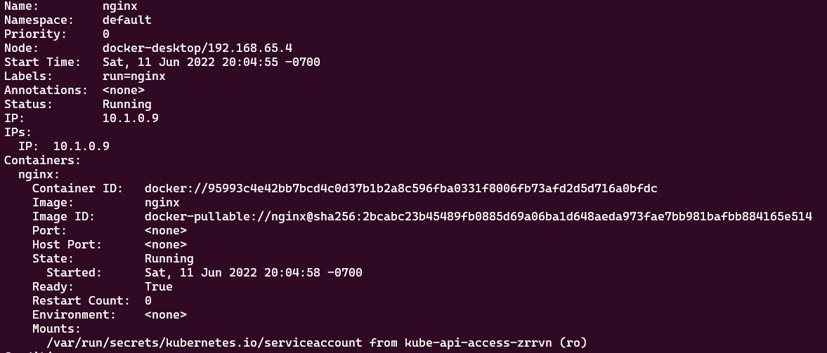
Figure 7.30 – When multi-container pods share a network
You can deploy a pod named busybox with the latest Busybox container image in the default namespace and then execute the nslookup command to check out the DNS address of the nginx pod, as shown in the following:
kubectl run -it busybox --image=busybox:latest
kubect exec busybox -- nslookup 10.1.0.9
The output should look as follows:

Figure 7.31 – When multi-container pods share a network
Alternatively, you can also use the following command to achieve the same outcome. Note that we are adding two rm flags in the command, which will make sure the pod is deleted once we exit the shell. We also use -- to execute the nslookup command directly. In this way, it allows us to do a quick test, which comes in very handy in the actual CKA exam. The command would look as follows:
kubectl run -it sandbox --image=busybox:latest --rm --restart=Never -- nslookup 10.1.0.9
The output should look as follows:
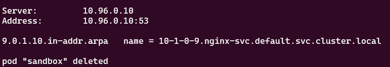
Figure 7.32 – When multi-container pods share a network
We notice that the only difference is that we get the pod "sandbox" deleted message, which indicates a pod named sandbox gets deleted once we exit the shell. The preceding output shows the DNS name of the nginx pod with the IP address 10.96.0. 10. The PTR record returns the DNS name of this pod as 10-1-0-9.default.pod.cluster.local just as we expected.
Now, let’s get the A record of the nginx pod in the default namespace by using the following command:
kubectl run -it sandbox --image=busybox:latest --rm --restart=Never -- nslookup 10-1-0-9.default.pod.cluster.local
The output is as follows:
Server: 10.96.0.10
Address 1: 10.96.0.10 kube-dns.kube-system.svc.cluster.local
Name: 10-1-0-9.default.pod.cluster.local
Address 1: 10.1.0.9
pod "sandbox" deleted
The preceding output proves that the DNS server returns the A record of the nginx pod. Let’s deploy a new nginx pod called test-nginx to test out the connectivity by using the following command:
$ kubectl run -it test-nginx --image=nginx --rm --restart=Never -- curl -Is 10-1-0-9.default.pod.cluster.local
The output will look as follows:

Figure 7.33 – When multi-container pods share a network
The preceding screenshot with 200 responses proves that the connectivity between the test-nginx pod and nginx pod is good and we managed to use the curl command on the main page of nginx with the DNS name of the nginx pod.
Up until this point, we have done a thorough run-through of how IP addresses and DNS work for the pods in a Kubernetes cluster. As we mentioned earlier in this chapter, Kubernetes creates DNS records not only for pods but also for services. Now, let’s take a look at how the service IP and DNS work in Kubernetes in the next section.
Service IPs and DNS hostnames
The DNS service in Kubernetes creates DNS records for services so you can contact services with consistent fully qualified DNS hostnames instead of IP addresses. Similarly, for a service in Kubernetes, the DNS follows the following pattern:
<service-name>.<namespace-name>.svc.cluster.local
Knowing that the DNS server is located in the kube-system namespace, we can check it out by using the following command:
kubectl get svc -n kube-system
The output is as follows, where we can get a look at the IP address of the DNS server in Kubernetes:
Figure 7.34 – When multi-container pods share a network
The preceding screenshot shows the IP address of the DNS server is 10.96.0.10. Now, let’s check out whether we can get the DNS name of the current DNS server by using the following command:
kubectl run -it sandbox --image=busybox:latest --rm --restart=Never -- nslookup 10.96.0.10
The output should be as follows:

Figure 7.35 – When multi-container pods share a network
The preceding screenshot proves that the DNS name for the DNS server follows the aforementioned pattern from this section. Here is how it looks:
kube-dns.kube-system.svc.cluster.local
Let’s now take a look at exposing a service for the nginx pod. We’re using the following command to expose the ClusterIP service of the nginx pod on port 80:
kubectl expose pod nginx --name=nginx-svc --port 80
The following output shows that it has been exposed successfully:
service/nginx-svc exposed
Based on the previous experiment with the kube-dns service DNS name, we can expect the nginx-svc service to follow the general service DNS name pattern, which will look as follows:
nginx-svc.default.svc.cluster.local
Now, let’s take a look at the services currently in the default namespace of our Kubernetes cluster by using the following command:
kubectl get svc
We can see an output similar to the following:

Figure 7.36 – The services in the Kubernetes default namespace
From the preceding output, we can get a closer look at nginx-svc by using the kubectl get svc nginx-svc -o wide command. The output is as follows:
NAME TYPE CLUSTER-IP EXTERNAL-IP PORT(S)
AGE SELECTOR
nginx-svc ClusterIP 10.107.75.83 <none> 80/TCP
59m run=nginx
The preceding command shows that the IP address of nginx-svc is 10.107.75.83, so let’s use the nslookup command to check out its DNS name. Use the following command:
kubectl run -it sandbox --image=busybox:latest --rm --restart=Never -- nslookup 10.107.75.83
The preceding command will give you the following output:

Figure 7.37 – Returning the DNS name for nginx-svc by looking up the IP address
Based on the preceding output, we can see that the DNS name for nginx-svc is nginx-svc.default.svc.cluster.local, which proves our assumption. Let’s get the DNS A record of nginx-service from the default namespace using the following command:
kubectl run -it sandbox --image=busybox:latest --rm --restart=Never -- nslookup nginx-svc.default.svc.cluster.local
You’ll see the output is similar to the following:
Server: 10.96.0.10
Address 1: 10.96.0.10 kube-dns.kube-system.svc.cluster.local
Name: nginx-svc.default.svc.cluster.local
Address 1: 10.107.75.83 nginx-svc.default.svc.cluster.local
pod "sandbox" deleted
The preceding output shows the DNS server, which was what we saw earlier in this section – the kube-dns service with the IP address 10.96.0.10 and under the kube-dns.kube-system.svc.cluster.local DNS name. Also, for our nginx-svc, we get an IP address of 10.107.75.83 in return.
Now, similar to how we tested the nginx pod, let’s test out the connectivity of the nginx service. We can use a pod called challenge-nginx and then run the curl command to see what’s coming back. The complete command is as follows:
kubectl run -it challenge-nginx --image=nginx --rm --restart=Never -- curl -Is http://nginx-svc.default.svc.cluster.local
The preceding command leads to the following output:
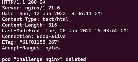
Figure 7.38 – Returning the DNS name for nginx-svc by looking up the IP address
The preceding screenshot with 200 responses proves the connectivity between the nginx-challenge pod and the nginx-svc service is good, and we managed to use the curl command on the main page of nginx with the DNS name of the nginx service. Knowing the nginx service is exposed from a nginx pod, in real life, we could deploy a number of replicas of this nginx pod, and expose them with one service. The traffic is distributed through the service to each pod.
Summary
This chapter covered Kubernetes networking. It covered the Kubernetes networking model and core networking concepts, as well as how to choose CNI plugins. Working with the Ingress controller and configuring and leveraging CoreDNS in Kubernetes helps you understand how to manage cluster networking and controller access to the applications in Kubernetes.
Make sure you have practiced these examples as you will encounter them often. Notice that this chapter covers 20% of the CKA exam content. Practicing the kubectl commands will help you with better time management, which leads to a greater chance of success in the CKA exam. Together with what we’ll talk about in the next chapter about monitoring and logging Kubernetes clusters and applications, you will get a better idea of how to manage Kubernetes clusters in your daily job as a Kubernetes administrator. Stay tuned!
Mock CKA scenario-based practice test
You have two virtual machines, master-0 and worker-0; please complete the following mock scenarios.
Scenario 1
Deploy a new deployment, nginx, with the latest image of nginx for two replicas in a namespace called packt-app. The container is exposed on port 80. Create a service type of ClusterIP within the same namespace. Deploy a sandbox-nginx pod and make a call using curl to verify the connectivity to the nginx service.
Scenario 2
Expose the nginx deployment with the NodePort service type; the container is exposed on port 80. Use the test-nginx pod to make a call using curl to verify the connectivity to the nginx service.
Scenario 3
Make a call using wget or curl from the machine within the same network as that node, to verify the connectivity with the nginx NodePort service through the correct port.
Scenario 4
Use the sandbox-nginx pod and nslookup for the IP address of the nginx NodePort service. See what is returned.
Scenario 5
Use the sandbox-nginx pod and nslookup for the DNS domain hostname of the nginx NodePort service. See what is returned.
Scenario 6
Use the sandbox-nginx pod and nslookup for the DNS domain hostname of the nginx pod. See what is returned.
You can find all the scenario resolutions in Appendix - Mock CKA scenario-based practice test resolutions of this book.
FAQs
- Where can I find the latest updates about Kubernetes networking while working with Kubernetes?
The Kubernetes networking Special Interest Group (SIG) has a GitHub repository that you can follow here: https://github.com/kubernetes/community/blob/master/sig-network/README.md.
- What is the recommended official Kubernetes article for Kubernetes networking?
I recommend bookmarking the official documentation about the following topics: