Chapter 17. BYOD: Self-Service Onboarding and Registration
Back in January 2007, Steve Jobs introduced the iPhone and suggested that Apple was shooting for 1% of the mobile device market. The device had a multi-touch screen interface, boasted a “real browser” instead of the cut-down versions on mobile devices to that point and arguably “changed the game” for the experience that users expected from their mobile devices from that point on. In January 2010, the iPad was released. In June 2010, I was at CiscoLive in Las Vegas presenting a session on Network Access Control (NAC).
In that session, I asked the audience if their company would allow users to bring in iPhones and iPad-type devices and connect to the corporate network for purposes of doing work from those devices. The few hundred people in my sample-size responded with about 90% no-way, and only a 10% affirmative response.
At that same conference, Cisco announced the CIUS, which was designed to be a “corporate tablet,” a device to provide that wonderful user-experience along with the security and guarantees that IT departments required. Fast forward 18 months, and Cisco announced the end-of-sale of the CIUS, due to lack of adoption. In June 2012, when asked the same question about allowing personal devices, the result was 90% affirmative and only 10% said their organizations would not allow personal devices. What a difference two years makes! Bring Your Own Device (BYOD) has become an absolute reality.
As shown in Figure 17-1, we are moving into an era of Bring Your Own Device (BYOD), Choose Your Own Device (CYOD), and even moving into a Bring Your Own App (BYOA) type of model. Employees are demanding the use of the devices that make them most productive, with native applications running on those platforms that provide the user experience they have become accustomed to. This introduces a new paradigm for security, especially the identification of the user, device, the location of the user, and much more.

BYOD Challenges
Because user identity is typically based on a single identity credential, IT does not possess the ability to create and enforce a rigorous secure access policy. Although the user might be authorized; the device, location, time, and access media can pose a company policy violation or even regulatory compliance violation that cannot be adequately detected or enforced.
This chapter focuses on the technical challenges of providing a secure BYOD access model. One of the most common challenges is referred to as onboarding. A user buys a new tablet or device and decides to connect it to the corporate WiFi and be productive on that consumer device. It has the challenge of identifying the device as a non-corporate device and provide a limited set of access to the device. This was originally what many companies used ISE to do. Figure 17-2 illustrates the flow of these original policies.

Then, mobile device management (MDM) solutions came into play. They were able to manage these mobile platforms to some extent. MDM policies ensured that devices had security enabled such as: encryption, remote wipe capabilities, screen lock (pin lock), and so forth. The MDM could provision certificates down to the device and supplicant profiles to preconfigure the device to have network access. Then, ISE would provide the correct level of access for the devices based on the certificate the device had.
Figure 17-3 illustrates a policy that uses certificates to differentiate access.

MDMs typically cost money per device, and many companies were only looking for a good way to provision certificates and configure the device supplicant to use that certificate with 802.1X. The MDM cost was often prohibitive. The main objective was to provision the certificate and get the device on the network. Cisco customers were looking for a much easier and cheaper way to accomplish the onboarding aspect of network access.
Onboarding Process
This chapter focuses on two types of onboarding. The first is what Cisco calls BYOD onboarding, which includes registering the device with ISE, provisioning the certificate to the device, and configuring the device’s supplicant. This uses the native supplicant within the operating system. It does not install a new one. The second is MDM onboarding, which is the process of registering the device with the MDM, installing the MDM client software, and enforcing the security policy on that device. The key to successful onboarding within a company is to make it self-service and not require involvement of IT.
BYOD Onboarding
ISE provides the My Devices portal, which allows users to register devices and manage those devices that have been registered. A device may simply be registered, which may provide one level of authorization, such as Internet-only access. Or the device may go through the full-blown onboarding and provisioning process where the supplicant configuration is installed into the device along with the optional certificate (for EAP-TLS connectivity).
Regardless of your choice to use device-registration only or to use the full onboarding process, there can be a single-SSID or dual-SSID approach to the onboarding, plus wired access (of course).
Figure 17-4 depicts the dual-SSID approach, while Figure 17-5 depicts the single-SSID approach. A quick comparison of the approaches follows.

Dual SSID
This section reviews the dual-SSID model of onboarding:
![]() Employee does not need to configure the supplicant on the device.
Employee does not need to configure the supplicant on the device.
![]() Employee authenticates to a web form.
Employee authenticates to a web form.
![]() Employee connects to the open SSID before the provisioning process, and the employee must connect to the corporate SSID after the process.
Employee connects to the open SSID before the provisioning process, and the employee must connect to the corporate SSID after the process.
Single SSID
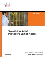
This section reviews the single-SSID model of onboarding (see Figure 17-5):
![]() Employee must configure the supplicant on the device to connect to the corporate SSID.
Employee must configure the supplicant on the device to connect to the corporate SSID.
![]() The authentication used to connect to the corporate SSID is used for single sign-on to the onboarding and provisioning process.
The authentication used to connect to the corporate SSID is used for single sign-on to the onboarding and provisioning process.
![]() A Change of Authorization (CoA) is used to provide full access after the provisioning process without requiring the employee to reconnect to the network.
A Change of Authorization (CoA) is used to provide full access after the provisioning process without requiring the employee to reconnect to the network.
Configuring NADs for Onboarding
Dual SSID onboarding uses an open WLAN configured for NAC RADIUS, IEEE 3576 (CoA) and uses only MAC filtering for security (Wireless MAB). This network is most likely created already based on Chapter 14, “Guest Lifecycle Management,” but this section briefly reviews the WLC settings.
Review of the WLC Configuration
This section briefly reviews the configuration for the Cisco wireless LAN controller.
The General tab of the WLAN should provide an SSID and profile name, as shown in Figure 17-6.

Under Security > Layer 2, Layer 2 security should be set to None. The MAC Filtering check box should be enabled, as displayed in Figure 17-7.

Under Security > Layer 3, Layer 3 security should be set to None, as shown in Figure 17-8.

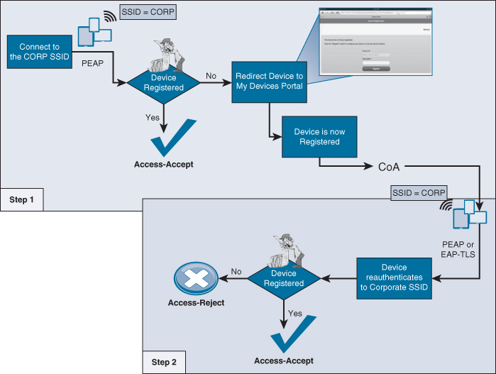
Under Security > AAA Servers, the ISE Policy Service mode(s) must be selected for authentication and accounting servers, as shown in Figure 17-9.
For the Advanced tab, configure the following: Allow AAA Override, and NAC State should be RADIUS NAC, as shown in Figure 17-10.

Double-check that the RADIUS Server Definition is configured to allow CoA, which is the RFC 3576 drop-down, as shown in Figure 17-11.

Required ACLs
You should have an ACL on the switches and the wireless controllers already named ACL-WEBAUTH-REDIRECT that permits DHCP, DNS, and traffic to ISE and denies most other traffic. This configuration was discussed and added in Chapter 14.
When onboarding with iOS, Windows and Mac OS, the endpoint need only communicate with ISE. iOS uses its native Over the Air (OTA) provisioning process. Windows and MAC both use a Java-based wizard that is downloaded from ISE through the devices browser. Because the communication is limited to just ISE, the ACL-WEBAUTH-REDIRECT ACL is sufficient to be repurposed for the onboarding ACL as well.
However, Android is a different story altogether. Android devices inherently do not trust apps being installed from an app store other than those trusted during the factory install. Therefore, ISE would not be allowed to host the app for Android devices by default. To keep the process simple for the end user, you have to open up the ACL to allow access to a range of addresses for Google Play.
The Google Play app store (play.google.com) is a cloud service, and the addresses it uses may change regularly. This presents a challenge to permit access to those ranges. The current solution is to permit a series of blocks of addresses that are known to be used by the Android Marketplace, as shown here:
![]() 74.125.0.0/16
74.125.0.0/16
![]() 173.194.0.0/16
173.194.0.0/16
![]() 173.227.0.0/16
173.227.0.0/16
![]() 206.111.0.0/16
206.111.0.0/16
These ACLs are used for both single and dual SSID onboarding. Here is a URL to a Google support thread, where Google discusses how to identify the current list of addresses: http://support.google.com/a/bin/answer.py?hl=en&answer=60764.
Create the ACL on the Wireless LAN Controller
From the WLC GUI, under Security > Access Control Lists, add a new ACL named Android-Marketplace, and configure the ACL as the one in Figure 17-12. The sample ACL is permitting all traffic from the inside network to speak to the client. It is allowing the client to communicate into the network for DNS and DHCP, as well as TCP traffic destined to the ISE servers. Next will be the lines that permit TCP traffic to the Android Market IP address ranges.

Create the ACL on the Switch
From the WLC GUI, under Security > Access Control Lists, add a new ACL named Android-Marketplace, and configure the ACL as the one in Example 17-1. This ACL is allowing DNS to bypass redirection, along with all four of the known Android Marketplace address ranges; all other web traffic will be redirected to ISE.
Example 17-1. Android-Marketplace ACL for Switches
ip access-list extended Android-Marketplace
deny udp any any eq domain
deny tcp any 74.125.0.0 0.0.255.255
deny tcp any 173.194.0.0 0.0.255.255
deny tcp any 173.227.0.0 0.0.255.255
deny tcp any 206.111.0.0 0.0.255.255
permit tcp any any eq www
permit tcp any any eq 443
ISE Configuration for Onboarding
With the NADs prepared for the onboarding process, it’s time to build the logic within the ISE Authorization Policy for both the dual and single SSID onboarding models.
The easier model to set up and understand first is the single SSID model. It assumes that, in order for a user or endpoint to be successfully admitted to the network, it must have authenticated with a certificate via EAP-TLS. If an authentication occurs with only a username and password (say, MsCHAPv2 inner method), you know the device must be onboarded.
For example, an employee shows up to work with their new mobile device. He decides to try and connect to the corporate WiFi, and it prompts him for a username and password. The employee enters his Active Directory credentials (as would be expected) and when he opens the browser on the mobile device, he is redirected to the My Devices portal, where he can begin the onboarding process. Simple, quick, and intuitive to most end users nowadays.
The first step is to configure the client provisioning portal so the correct profiles are sent for the appropriate operating systems. From there, configure the default action that should be taken when an unsupported device is sent to be provisioned.
End-User Experience
To fully understand the configuration of ISE, it is best that you experience the end-user experience for both single and dual SSID onboarding. That will aid you in your understanding of each policy that must be created, and each choice you will have to make. To demonstrate multiple user experiences, the following examples will use Apple iOS for one and Android for the other. However, each onboarding method could be used with any of the supported clients (iOS, Android, Mac OS X, and Windows).
Single-SSID with Apple iOS Example
The following steps are designed to follow the end-user experience with single-SSID onboarding, using an Apple iOS device:
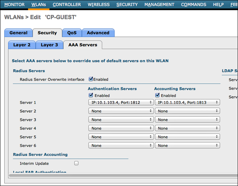
1. You come in with your iOS device. Open Settings and connect to the corporate WiFi, such as what is shown in Figure 17-13.
2. You are prompted to input a username and password. Use your Active Directory username and password, as shown in Figure 17-14.

3. If the certificate used by ISE is not signed by a trusted root, you are prompted to accept (trust) the certificate used by ISE, as shown in Figure 17-15.

4. Now you are successfully connected to the corporate network. Yet, you will not know that your access is actually limited, as shown in Figure 17-16.

5. Open a web browser, and you are redirected to the client provisioning portal, where OTA will begin.
6. The first step with OTA is to send the root CA’s certificate to the iOS device to be trusted for OTA, as shown in Figure 17-17.

7. Click Install. A warning message is displayed about the root CA being added to the list of trusted certificates on the device, along with a warning about the profile itself (if the certificate was not in the trusted store already), as shown in Figure 17-18.

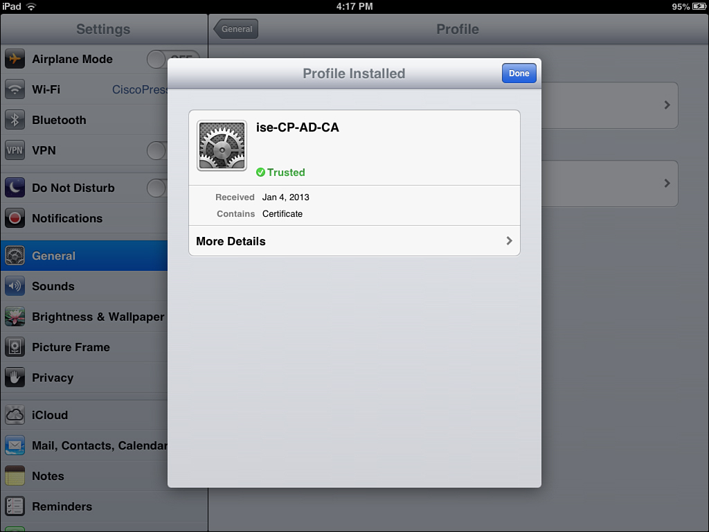
8. The Certificate and Profile to allow OTA is successfully installed. Click Done, as shown in Figure 17-19.
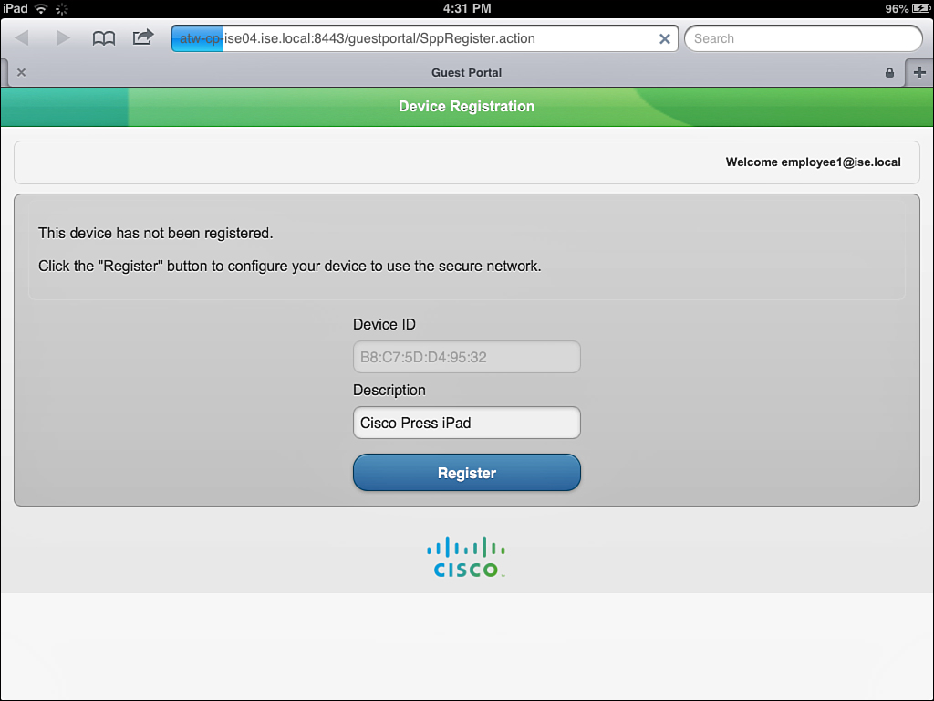
9. You are returned to your browser window, which displays the Device Registration page within the My Devices portal. The Device’s MAC address will be prepopulated and noneditable. There is a description field for you to fill out, as shown in Figure 17-20.
10. Click Register. The screen immediately changes to the Install Profile Service, as shown in Figure 17-21.
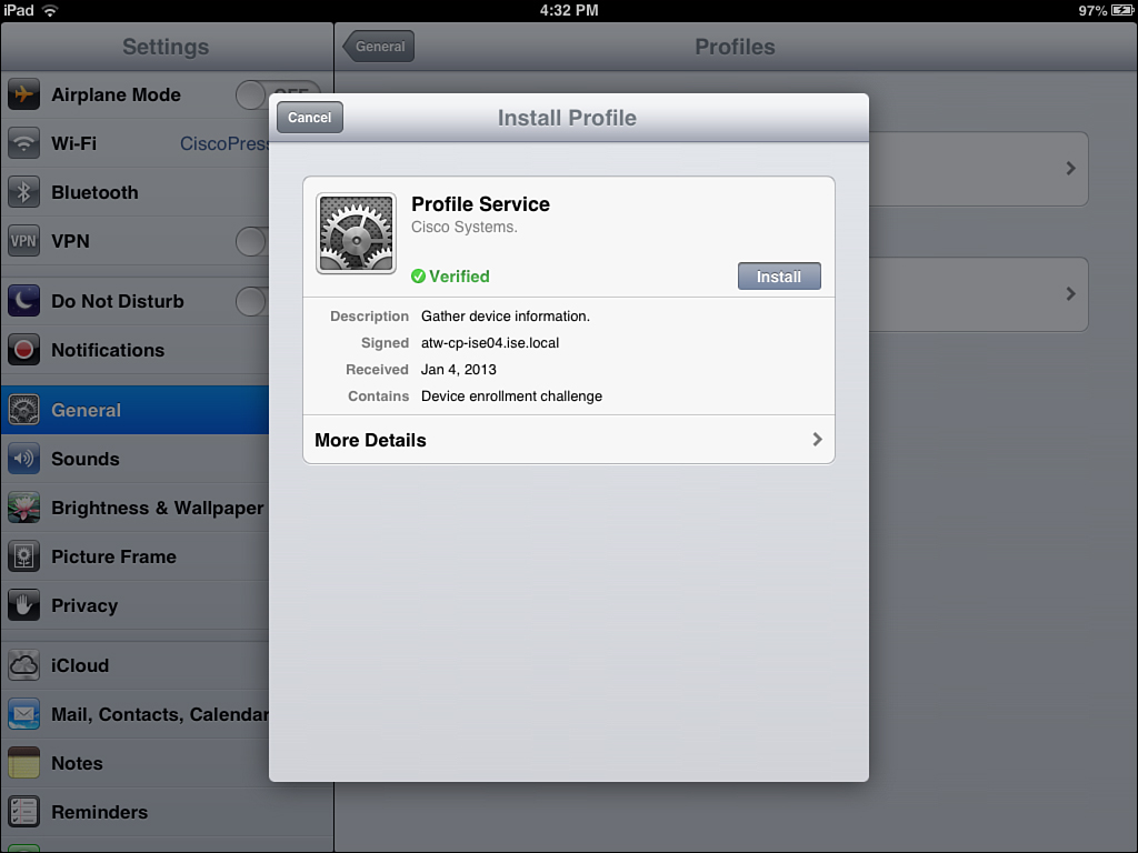
11. You are warned that clicking Install Profile will actually install a profile. Click Install Now, as shown in Figure 17-22.

12. The profile begins to install, generates a certificate using SCEP, and prepares the device to be connected to the corporate SSID. The progression is shown in Figures 17-23 through 17-26.


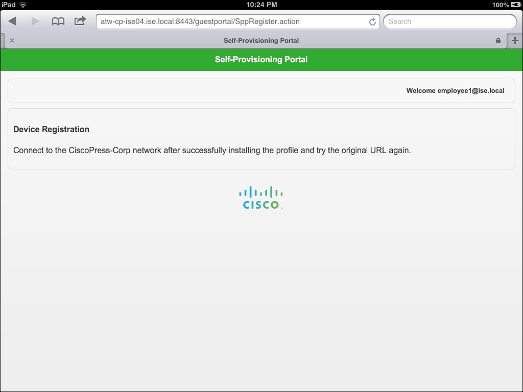
13. When the profile is installed, click Done and return to your web browser where the success message is waiting for you, as shown in Figure 17-27.
14. You are now able to browse resources on the network, as shown in Figure 17-28.
That concludes the onboarding process for iOS with a single SSID. Next, let’s examine the user experience with dual SSID by using an Android example.
Dual SSID with Android Example
The following steps are designed to follow the end-user experience with dual-SSID onboarding, using an Android-based device.
1. You come in with your Android device. Open Settings and connect to the Guest WiFi, as shown in Figure 17-29.
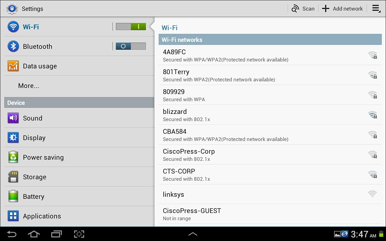
2. Because you protected the guest WiFi by requiring a login (Guest or Active Directory), you are redirected to the Web Authentication page, as shown in Figure 17-30.

3. After you log into the Web Auth portal, you are redirected to the device registration page. The device ID is predefined, as shown in Figure 17-31.
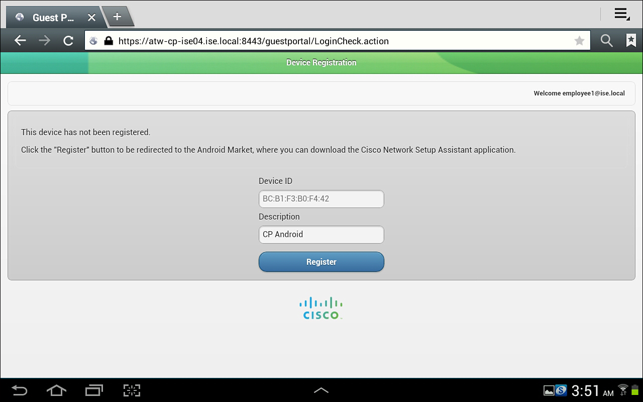
4. Click Register. You are prompted to connect to the Android Marketplace (play.google.com) and given the choice between the Internet and the app, as shown in Figure 17-32.

5. Download the app from the marketplace, as shown in Figure 17-33.

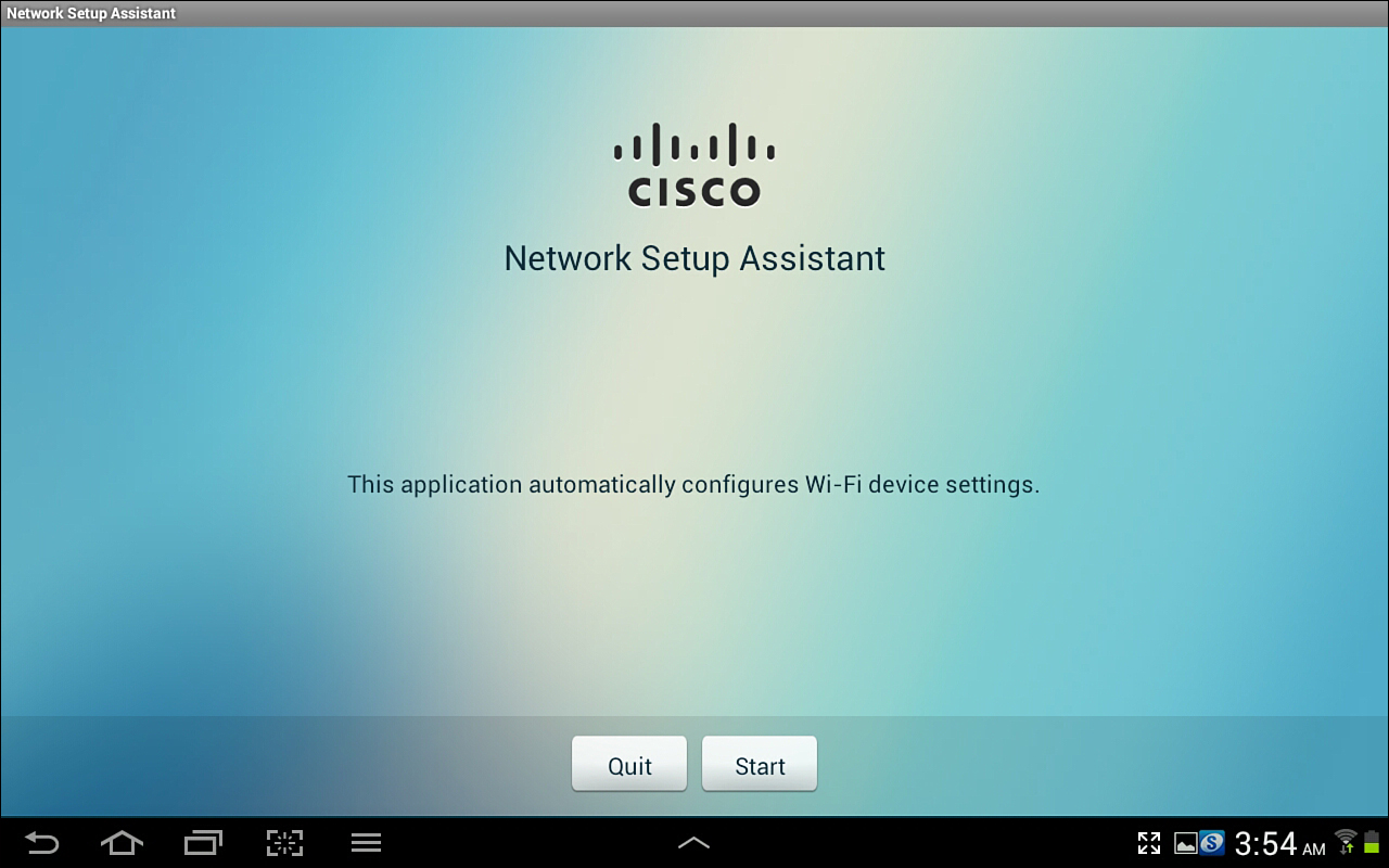
6. Run the app and click Start, as shown in Figure 17-34.
7. The NSP app downloads the profile from ISE, as shown in Figure 17-35.

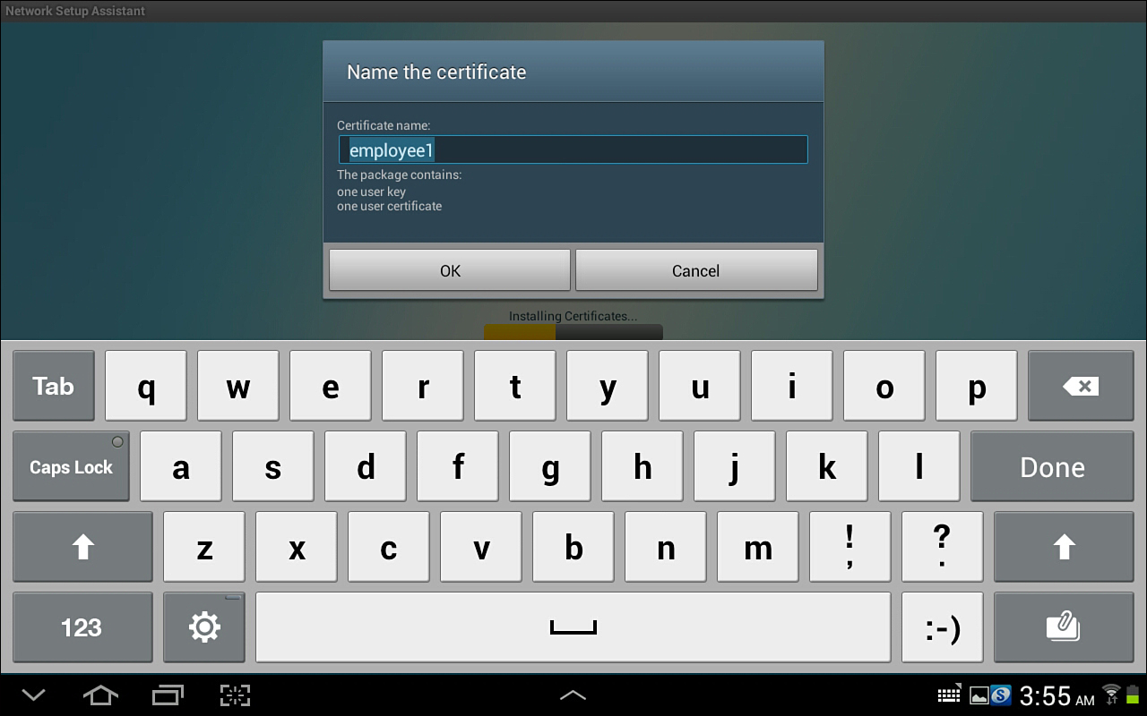
8. Name your certificate, as shown in Figure 17-36.
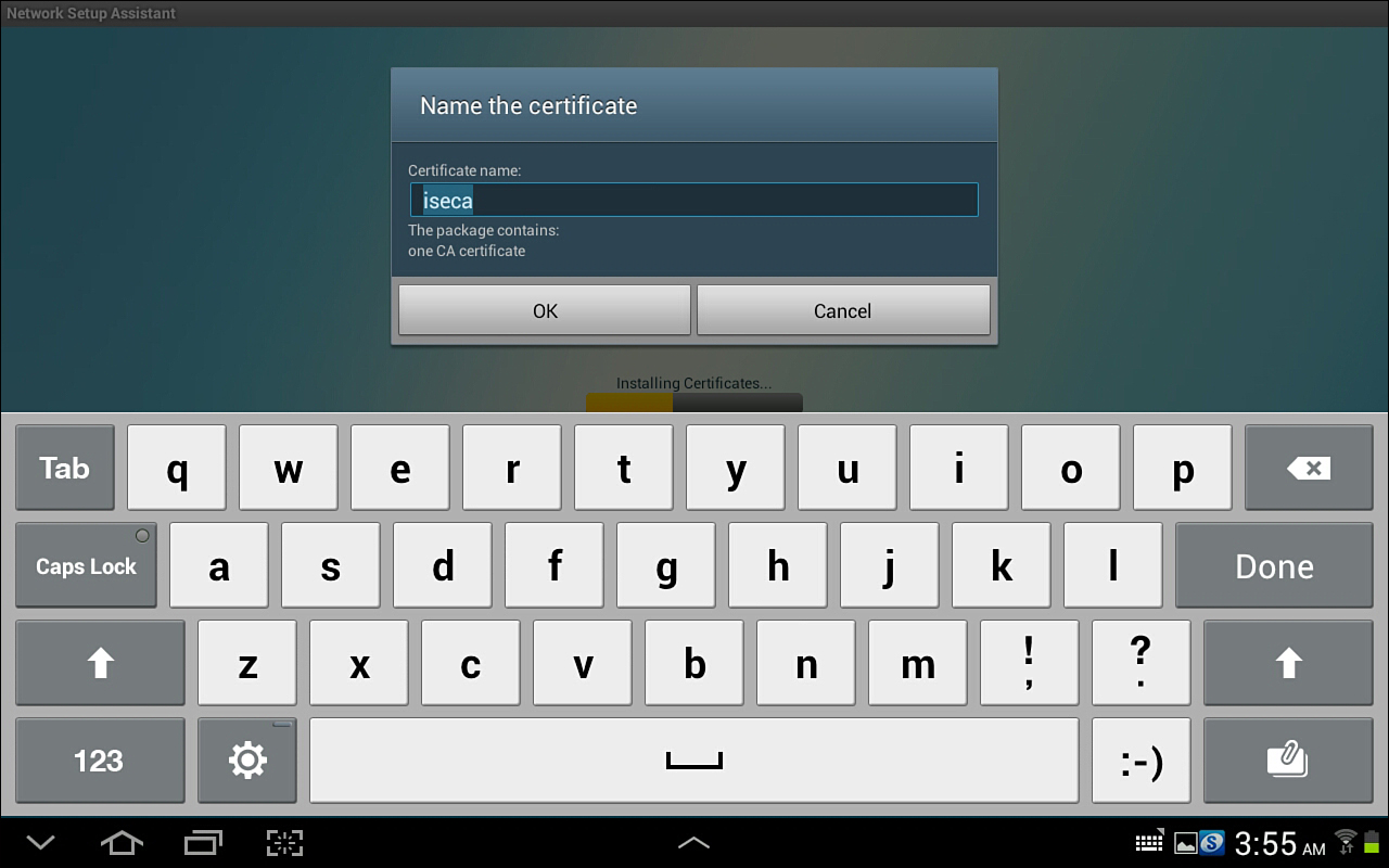
9. Name the CA certificate, as shown in Figure 17-37.
10. The NSP app automatically changes the network connection to the corporate SSID and authenticates with the new certificate using EAP-TLS, as shown in Figure 17-38.

11. Your Android device is now ready to be used regularly on the corporate network, as shown in Figure 17-39. The onboarding was a one-time thing.

Unsupported Mobile Device: Blackberry Example
You’ve seen both single and dual SSID onboarding with supported devices. Let’s look at a brief example of a device that is not supported:
1. You bring your Blackberry mobile device to work and select the GUEST Wireless network, as shown in Figure 17-40.

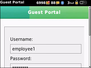
2. The web browser is redirected to the Web Authentication page, where you enter your Active Directory credentials, as shown in Figure 17-41.
3. If the global setting is Apply Defined Authorization Policy, you receive the message shown in Figure 17-42 and will not be able to gain network access. This is covered in more detail later in this chapter.

4. If the global setting is Allow Network Access, you receive a notification that you may register the device through the My Devices portal, as shown in Figure 17-43. This is covered in detail later in this chapter.

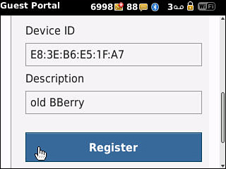
5. You are now allowed to register the device and gain network access with manually configuring your supplicant, as shown in Figure 17-44.
Configuring ISE for Onboarding
The end-user experience is designed to be straightforward and easy for a typical user to be able to follow without any interaction with the IT department. To keep things easy for the end user, there is some up-front work you will need to do on the configuration side. We will cover the entire configuration in this section.
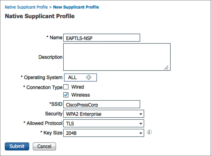
Creating the Native Supplicant Profile
This subsection focuses on the creation of the native supplicant profile, which defines the network settings for the endpoints that will go through onboarding.
The native supplicant profile defines the following:
![]() Wireless SSID
Wireless SSID
![]() EAP type to use (PEAP or EAP-TLS)
EAP type to use (PEAP or EAP-TLS)
![]() Level of wireless security
Level of wireless security
![]() If it applies to wired, wireless, or both
If it applies to wired, wireless, or both
The following steps guide you through adding the latest client provisioning resources from the Cisco site, and then creating the native supplicant profile.
1. Navigate to Policy > Policy Elements > Results > Client Provisioning.
2. Select Resources.
3. Click Add > Agent Resources from Cisco site.
4. Select the latest versions of the clients and wizards, as shown in Figure 17-45.

5. Click Save.
6. Click Add > Native Supplicant Profile.
7. Name the native supplicant profile EAPTLS-NSP.
8. Operating system may remain the default of ALL.
9. Ensure that Wireless is checked.
10. Wired is optional.
11. Provide the SSID for the corporate wireless network.
12. Select the security level (such as WPA2).
13. Choose TLS for the allowed protocol.
14. Select the certificate size (such as 2048).
15. Click Submit.
Figure 17-46 shows the completed native supplicant profile.
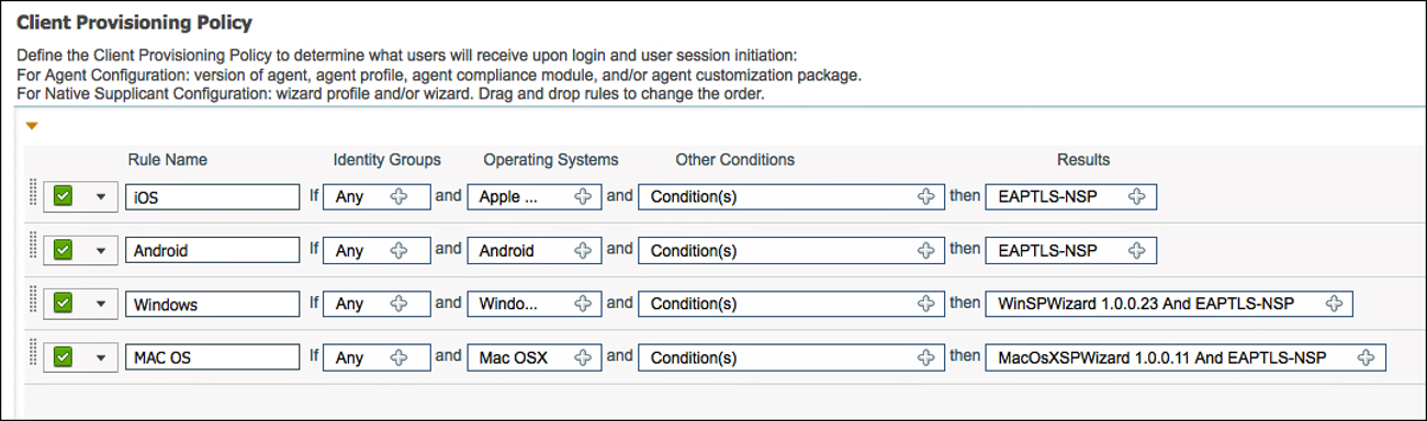
Configure the Client Provisioning Policy
You configure a Client Provisioning Policy to dictate the software and profiles that should be downloaded and installed based on the operating system of the endpoint and a multitude of other possible attributes. For example, you might configure a policy for Android to be provisioned for the CORP-SSID wireless network when an employee is going through the provisioning process while configuring the CONTRACTOR-SSID for all vendors and contractors who are also working through the provisioning process.
For our example, let’s create one client provisioning policy per OS using the following steps:
1. Navigate to Policy > Client Provisioning.
2. Name a new rule iOS.
3. Set the operating system as Apple iOS Al.l.
4. Set the result to be the EAPTLS-NSP supplicant profile.
Note
The ISE client provisioning portal automatically uses the Over the Air (OTA) provisioning process that is native to iOS for Apple iOS. There is no need to specify that here.
5. Insert a new rule below the iOS rule; name that rule Android.
6. Set the operating system as Android.
7. Set the result to be the EAPTLS-NSP supplicant profile.
Note
The ISE client provisioning portal automatically redirects Android devices to play.google.com to download the supplicant-provisioning app. There is no ability to specify a different app store.
8. Insert a new rule below the Android rule; name that rule Windows.
9. Set the operating system as Windows All.
10. Configure the results to use the WinSPWizard AND EAPTLS-NSP, as shown in Figure 17-47.

The drop-down provides many more possibilities for Windows, because we also have the ability to provision the NAC agent or web agent to the Windows operating system. Windows uses the Cisco Supplicant Provisioning wizard (a Java applet) to implement the provisioning, and that must be specified here.
11. Insert a new rule below the Windows rule; name that rule MAC OS.
12. Set the operating system as Mac OS X.
13. Configure the results to use the MacSPWizard AND EAPTLS-NSP.
Like Windows, the drop-down choices for Mac OSX provide many more possibilities, because you have the ability to also provision the NAC agent to the Mac OS X operating system. MAC OS will use the Cisco Supplicant Provisioning wizard (a Java applet) to implement the provisioning, and that must be specified here.
Figure 17-48 shows the final client provisioning policy.
Configure the WebAuth
The client provisioning policy is now created, and it will be used with both dual-SSID and single-SSID provisioning. However, you must ensure that the Web Auth Portal page is ready for the dual-SSID flow.
There is a plethora of options when it comes to Web Authentication and supplicant provisioning. For instance, it is absolutely possible to configure different web portals based on a number of attributes available from the authentication request (such as source SSID). This way, you can enable the device registration and supplicant provisioning to occur per use case, if you so choose.
For simplicity, use the DefaultGuestPortal for your example:
1. Navigate to Administration > Web Portal Management > Guest.
2. Choose Multi-Portal Configuration > DefaultGuestPortal.
3. Click Operations.
4. Ensure the Enable Self-Provisioning Flow check box is selected, as shown in Figure 17-49.

5. Click Save.
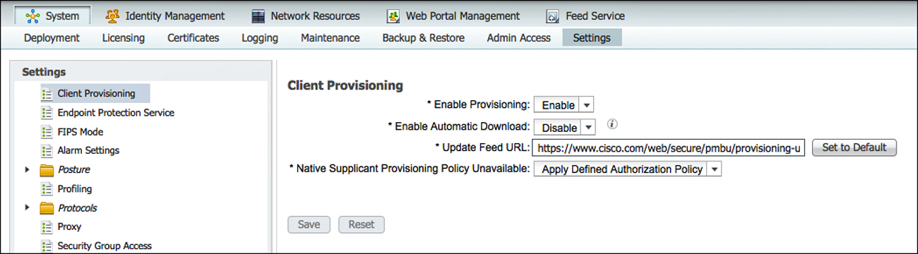
Verify Default Unavailable Client Provisioning Policy Action
ISE supports iOS, Android, Windows, and Mac OS X. However, it is possible for an end user to attempt access with a client that is not supported by ISE native supplicant provisioning (such as attempting with a BlackBerry or Windows Mobile device). ISE offers two options for that situation:
![]() Allow Network Access: With this option, users are allowed to register their device through the My Devices Portal and gain network access without having to install and launch a native supplicant wizard. This assumes the user will have to interact and configure the supplicant independently. This option may be attractive if the end users are capable of requesting and installing their own certificates.
Allow Network Access: With this option, users are allowed to register their device through the My Devices Portal and gain network access without having to install and launch a native supplicant wizard. This assumes the user will have to interact and configure the supplicant independently. This option may be attractive if the end users are capable of requesting and installing their own certificates.
![]() Apply Defined Authorization Policy: Basically, this option leaves the client in the current state, which is a state of limited access. This is also the default setting.
Apply Defined Authorization Policy: Basically, this option leaves the client in the current state, which is a state of limited access. This is also the default setting.
Figure 17-50 shows the setting for Native Supplicant Provisioning Policy Unavailable.
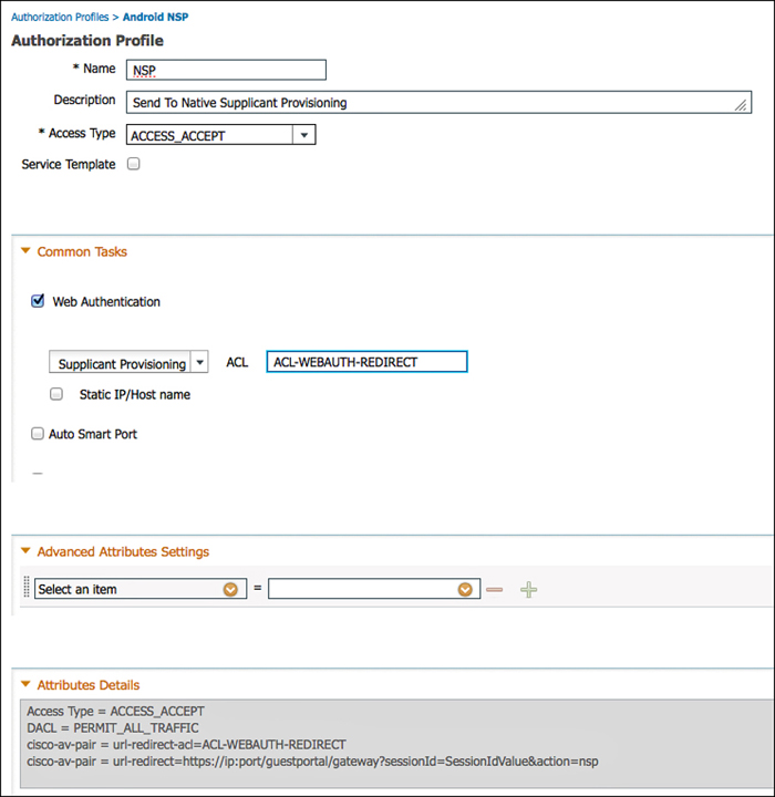
Create the Authorization Profiles
Although having the client provisioning policy is required, the Authorization Policy is still mission-critical. Without the properly configured Authorization Policy, there is no “call to action” that sends the endpoint over to the client provisioning portal. Of course, an authorization rule needs an Authorization Policy that includes that call to action.
Create two authorization profiles, one for Android and another for the remaining devices:
1. Navigate to Policy > Policy Elements > Results > Authorization > Authorization Profiles.
2. Add a new authorization profile, named Android NSP.
3. Select a dACL to permit traffic when doing wired onboarding.
4. Select Web Authentication.
5. From the drop-down, choose Supplicant Provisioning.
6. Enter the Android Marketplace ACL.
7. Click Submit.
Figure 17-51 shows the Android NSP authorization profile.

8. Add a new authorization profile, named NSP.
9. Select a dACL to permit traffic when doing wired onboarding.
10. Select Web Authentication.
11. From the drop-down, choose Supplicant Provisioning.
12. Enter the ACL-WEBAUTH-REDIRECT ACL.
13. Click Submit.
Figure 17-52 shows the NSP authorization profile.
Create the Authorization Policy Rules
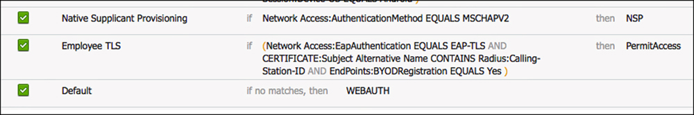
Now you have the authorization profiles, you need to create the authorization rules that use those profiles for results. Create two authorization rules that result in a client provisioning action: one for Android and another for the remaining devices. Lastly, create an authorization rule that permits the devices that have already been provisioned.
The following steps create the Android NSP authorization rule:
1. Navigate to Policy > Authorization.
2. Add a new rule, just above the default rule.
3. Name the rule Android NSP.
4. Set the conditions as
Network Access:AuthenticationMethod EQUALS MSCHAPV2
And
Session:Device-OS EQUALS Android
5. Set the authorization result to be the Android NSP created earlier.
6. Click Done.
Now you’ve created the Android NSP Rule is created. What is remaining is to create the non-Android (all other devices) rule, and rule for any devices that have already been onboarded. The following steps configure the non-Android provisioning rule:
1. Add a new rule, just above the default rule and below the Android rule.
2. Name the rule Native Supplicant Provisioning.
3. Set the conditions as
Network Access:AuthenticationMethod EQUALS MSCHAPV2
4. Set the authorization result to be the NSP Authorization profiler created earlier.
5. Click Done.
Now you have created both provisioning rules in the authorization table, all that remains is to add the EAP-TLS rule for successful authentications. The following steps create a rule that matches authentications using certificates and ensures that the MAC address of the endpoint matches the MAC address burned into the certificate during the onboarding process:
1. Add a new rule, just above the default rule and below the NSP rule.
2. Name the rule Employee TLS.
3. Set the conditions as
Network Access:AuthenticationMethod EQUALS x509_PKI
And
CERTIFICATE:Subject Alternative Name CONTAINS Radius:Calling-Station-ID
Endpoints:BYODRegistration EQUALS Yes
4. Set the authorization result to be Permit Access.
5. Click Done.
6. Click Save.
Figure 17-53 shows the completed authorization policy with all three of the new rules.
Configure SCEP
ISE acts as a registration authority (RA) for the certificate enrollment and provisioning of the devices that are being onboarded. So, with ISE 1.2, ISE is not the certificate authority (CA); instead it is a “broker” of sorts that uses Simple Certificate Enrollment Protocol (SCEP) to request and provision a certificate to the client from the CA of your choice.
Multiple CAs could be used. Although it is not commonly deployed, Cisco offers CA functionality in the higher-end routers, like the 7200, 7300, and 7600 series routers, as well as integrated services routers (ISR). At the time of this publishing, no CA function is available for the aggregated services router (ASR).
At present, the most common CA seems to be the Microsoft Certificate Authority. The Microsoft CA has support for SCEP and it is called Network Device Enrollment Services (NDES). It requires Windows 2008 R2 Enterprise or newer and that server must be part of a domain.
Note
There are companies who have created a brand-new Active Directory domain with only the one server in it, just for the CA and NDES functionality to be separate from their production AD. This is not necessarily recommended, just noting the example to show the level of flexibility you might have, if needed. For more details on the configuration of a Microsoft CA, refer to Appendix C, “Configuring the Microsoft CA for BYOD.”
You may use any CA of your choosing, as long as it meets the requirements:
![]() Must support SCEP
Must support SCEP
![]() Must support an automated or automatic issuing of the requested certificates
Must support an automated or automatic issuing of the requested certificates
The configuration of ISE to use the CA is simple. There is really just one setting to configure by using the following steps:
1. Navigate to Administration > System > Certificates.
2. Click SCEP RA Profiles.
3. Click Add.
4. Name the CA (example is CP_AD_CA).
5. Add the URL, such as http://ip-address-of-ca/certsrv/mscep/
6. Click Test Connectivity.
7. Click Submit.
Figure 17-54 shows the completed SCEP RA profile.

Assuming your CA configuration was complete, your deployment is now ready to do BYOD onboarding.
BYOD Onboarding Process Detailed
Yes, this chapter is getting very long. However, it is my hope that you will find all this information useful if you ever find yourself in a spot where you need to do troubleshooting of this process. You have seen that the user experience is simple and straightforward, but the process behind the scenes is complex.
iOS Onboarding Flow
We examine, in detail, the experience with iOS devices and onboarding. To do so, we are focusing on a single SSID onboarding experience. The end user should only have to complete four actions, as noted in Figure 17-55. However, we look at all the items that occur behind the scenes.
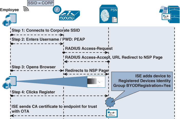
1. User joins the corporate SSID and the iOS device prompts the user for credentials.
2. The user enters his AD username and password.
3. The EAP login request is sent to the wireless controller, which wraps the request in a RADIUS access-accept request to ISE
4. The authorization result from ISE will include a URL-redirection to the NSP portal.
5. The user opens his web browser, which is redirected to the NSP portal on ISE, displaying the device-registration page with the device-ID pre-populated with the MAC address.
6. The user clicks register, which immediately triggers three events:
![]() Sets the BYODRegistration flag for the endpoint identity to Yes.
Sets the BYODRegistration flag for the endpoint identity to Yes.
![]() Adds the endpoint to the RegisteredDevices identity group.
Adds the endpoint to the RegisteredDevices identity group.
![]() Sends the CA’s certificate to the IOS device for it to trust for OTA.
Sends the CA’s certificate to the IOS device for it to trust for OTA.
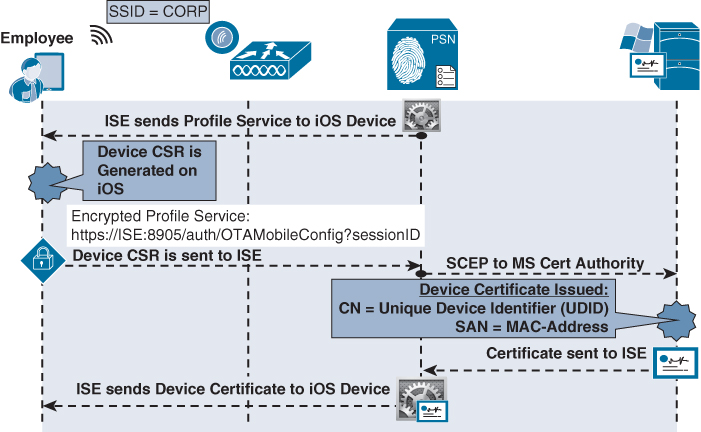
1. ISE sends a profile service to ISE via Over the Air Provisioning (OTA).
2. The profile instructs iOS to generate a Certificate Signing Request (CSR) using the Unique Device Identifier (UDID) as the certificate’s subject, and the MAC address as the Subject Alternative Name (SAN) field:
![]() CN=device-UDID
CN=device-UDID
![]() SAN=MAC-Address
SAN=MAC-Address
3. The device CSR is sent to ISE, which uses SCEP to proxy the certificate enrollment request to the CA.
4. The CA automatically issues the certificate.
5. The certificate is sent back to ISE, which sends it to the device through the OTA service.
Phase 2 is illustrated in Figure 17-56.
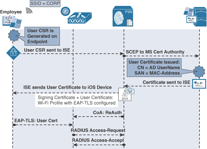
Phase 3: Device Provisioning
1. The iOS device generates another CSR, using the employee’s credentials (given to iOS by ISE via the OTA service) as the certificate’s subject, and the MAC address as the Subject Alternative Name (SAN) field:
![]() SAN=MAC-Address
SAN=MAC-Address
2. The user CSR is sent to ISE, which uses SCEP to proxy the certificate enrollment request to the CA.
3. The CA automatically issues the certificate.
4. The certificate is sent back to ISE, which sends it to the device through the OTA service. Included in that profile is the WiFi configuration, which details the SSID and to use EAP-TLS.
5. ISE sends a CoA to the NAD of the type ReAuth, which causes a new authentication.
6. The endpoint now authenticates to the corporate SSID using the certificate via EAP-TLS.
Phase 3 is illustrated in Figure 17-57.

Android Flow
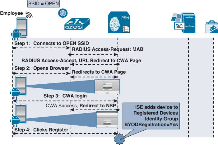
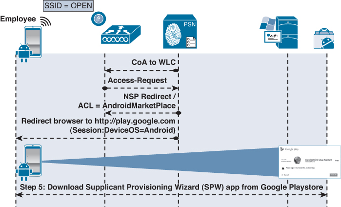
To detail the flow of onboarding with Android, we will use the dual-SSID approach. Android is certainly capable of doing a single-SSID approach as well. The end-user should only have to complete four actions, as noted in Figure 17-55. However, let’s take a look at all the items that occur behind the scenes.
Phase 1: Device Registration
1. User joins the open SSID, and ISE sends a redirection to the Centralized Web Authentication portal.
2. The WLC sends a MAC Authentication Bypass (MAB) request to ISE.
3. The authorization result from ISE will include a URL-redirection to the Centralized Web Authentication (CWA) portal.
4. The user opens a browser, and is redirected to the CWA portal.
5. The user enters his AD username and password.
6. The successful Web Auth triggers two events:
![]() The web page changes to the native supplicant provisioning portal.
The web page changes to the native supplicant provisioning portal.
![]() A CoA is sent to the WLC, which includes a redirection to the NSP portal.
A CoA is sent to the WLC, which includes a redirection to the NSP portal.
7. The NSP portal displays the device-registration page with the device-ID pre-populated with the MAC address of the endpoint.
8. User click Register, which immediately triggers five events:
![]() Sets the BYODRegistration flag for the endpoint identity to Yes.
Sets the BYODRegistration flag for the endpoint identity to Yes.
![]() Adds the endpoint to the RegisteredDevices identity group.
Adds the endpoint to the RegisteredDevices identity group.
![]() Sets the Session:Device-OS attribute to Android. (This is a temporary attribute and only used for the provisioning process.)
Sets the Session:Device-OS attribute to Android. (This is a temporary attribute and only used for the provisioning process.)
![]() Sends a CoA to the WLC to apply the correct ACL, allowing Google Marketplace access for the Android device.
Sends a CoA to the WLC to apply the correct ACL, allowing Google Marketplace access for the Android device.
![]() The web page sends the browser to Google Play Store.
The web page sends the browser to Google Play Store.
Phase 1 is illustrated in Figure 17-58.
Phase 2: Download SPW
1. The CoA from phase 1 applied an ACL that permits traffic to the Google Play Store (Android Marketplace).
2. The browser was automatically sent to the Google Play Store and the Android device prompts the user to choose the Internet or Play Store to complete the request.
3. The user may be prompted to login to the Google Play Store.
4. The user clicks to install the Cisco Network Setup Assistant app.
Phase 2 is illustrated in Figure 17-59.
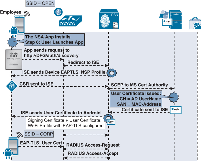
Phase 3: Device Provisioning
1. The Network Setup Assistant installs, and the user runs it.
2. The NSA sends a discovery message to http://default-gateway/auth/discovery
3. The WLC redirects that HTTP message to the ISE native supplicant provisioning portal based on the URL-REDIRECT result within the authorization from ISE.
4. ISE sends the Android profile based on the EAPTLS-NSP supplicant profile to the endpoint.
5. NSA generates the Certificate Signing Request (CSR), using the employee’s credentials as the certificate’s subject, and the MAC address as the Subject Alternative Name (SAN) field:
![]() CN=Username
CN=Username
![]() SAN=MAC-Address
SAN=MAC-Address
6. The CSR is sent to ISE, which uses SCEP to proxy the certificate enrollment request to the CA.
7. The CA automatically issues the certificate.
8. The certificate is sent back to ISE, which sends it to NSA app. Included in that profile is the WiFi configuration, which details the SSID and to use EAP-TLS.
9. The NSA app connects the endpoint to the corporate SSID and ISE sends a CoA to the NAD of the type ReAuth, which also causes a new authentication.
10. The endpoint now authenticates to the corporate SSID using the certificate via EAP-TLS.
Phase 3 is illustrated in Figure 17-60.
Windows and Mac-OSX Flow
Mac OS X and Windows both use a wizard to accomplish the onboarding and provisioning. It is a Java-based applet called the Cisco native supplicant provisioning wizard. The wizard takes care of triggering the CSR from the OS and installing the supplicant profile. This is only a two-phase process.
Phase 1: Device Registration
1. User joins the corporate SSID, and the iOS device prompts the user for credentials.
2. The user enters his AD username and password.
3. The EAP login request is sent to the wireless controller, which wraps the request in a RADIUS access-accept request to ISE.
4. The authorization result from ISE includes a URL-redirection to the NSP portal.
5. The user opens his web browser, which is redirected to the NSP portal on ISE, displaying the device-registration page with the device-ID pre-populated with the MAC address.
6. The user clicks register, which immediately triggers two events:
![]() Sets the BYODRegistration flag for the endpoint identity to Yes.
Sets the BYODRegistration flag for the endpoint identity to Yes.
![]() Adds the endpoint to the RegisteredDevices identity group.
Adds the endpoint to the RegisteredDevices identity group.
Phase 1 is illustrated in Figure 17-61.

Phase 2: Device Provisioning
1. The native supplicant provisioning wizard is downloaded and runs.
2. The NSP wizard sends a discovery message to http://default-gateway/auth/discovery.
3. The WLC redirects that HTTP message to the ISE native supplicant provisioning portal based on the URL-REDIRECT result within the authorization from ISE.
4. ISE sends the NSP profile based on the EAPTLS-NSP supplicant profile to the endpoint.
5. The NSP wizard generates the Certificate Signing Request (CSR), using the employee’s credentials as the certificate’s subject, and the MAC address as the Subject Alternative Name (SAN) field:
![]() CN=Username
CN=Username
![]() SAN=MAC-Address
SAN=MAC-Address
6. The CSR is sent to ISE, which uses SCEP to proxy the certificate enrollment request to the CA.
7. The CA automatically issues the certificate.
8. The certificate is sent back to ISE and is sent down to the NSP wizard. Included in that profile is the WiFi configuration, which details the SSID and to use EAP-TLS.
9. The NSP wizard connects the endpoint to the corporate SSID, and ISE sends a CoA to the NAD of the type ReAuth, which also causes a new authentication.
10. The endpoint now authenticates to the corporate SSID using the certificate via EAP-TLS.
Phase 2 is illustrated in Figure 17-62.
MDM Onboarding
Many organizations use MDM solutions. These solutions provide endpoint management for a plethora of devices. They help enforce specific security requirements, such as endpoint encryption, PIN lock, jail-break detection, remote wipe capabilities, and more. Many MDMs will even provision supplicants and certificates to devices as part of their management package.
What would typically occur is that a user would bring in a mobile device, and to gain access to the network, he had to call the helpdesk and receive instructions on how to onboard the device with the MDM, so he could gain access to the network. There are some significant downsides to this process, such as
![]() Users are required to manually connect to the MDM solution to begin the onboarding process.
Users are required to manually connect to the MDM solution to begin the onboarding process.
![]() There was no enforcement to help “steer” the user toward that solution.
There was no enforcement to help “steer” the user toward that solution.
![]() An MDM license was required for every device the organization would provision and allow to have network access, which can be cost prohibitive.
An MDM license was required for every device the organization would provision and allow to have network access, which can be cost prohibitive.
However, this presented a beneficial and strategic opportunity for Cisco and the MDM vendors. The MDM vendors possessed the mobile device-management capabilities, and Cisco had the onboarding, network access policy, and enforcement mechanisms.
ISE 1.2 adds the integration of five of the industries top MDM vendors:
![]() AirWatch
AirWatch
![]() Mobile Iron
Mobile Iron
![]() ZenPrise (acquired by Citrix)
ZenPrise (acquired by Citrix)
![]() Good Technologies
Good Technologies
![]() SAP Afaria
SAP Afaria
These five vendors have implemented an Application Programming Interface (API) written by Cisco to enable scalable bidirectional communication between their solution and ISE.
Integration Points
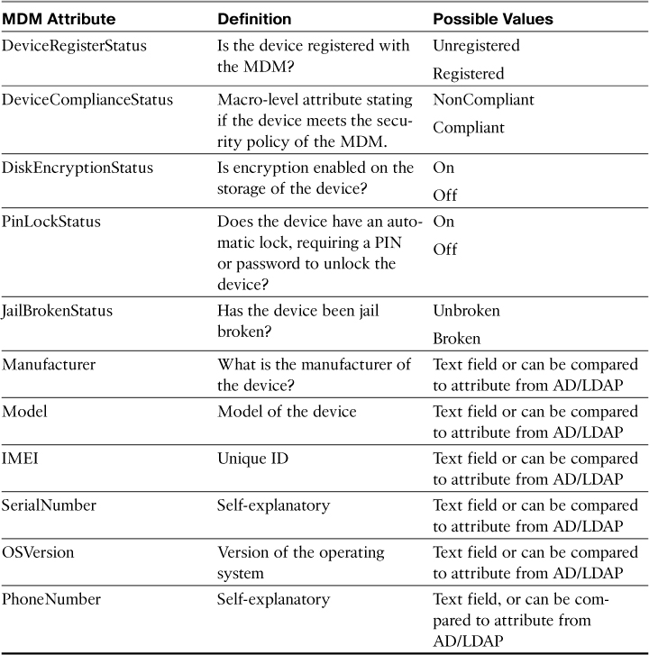
The API provides ISE with the ability to use MDM attributes in the authorization policies. The authorization may use a macro-level attribute stating that the device is in compliance with the MDM policy or Micro level attributes, such as jail break status, PIN lock, or even endpoint encryption.
Table 17-1 documents the possible MDM attribute values, provides a definition of each value, and lists the possible values for each attribute.
Configuring MDM Integration
Before you configure ISE to communicate with the MDM, ISE needs to trust the certificate of the MDM for the SSL-encrypted communications. You can accomplish this by using the following steps:
1. Navigate to Administration > Certificates.
2. Choose Certificate Store.
3. Import the Certificate of the MDM as a trusted certificate.
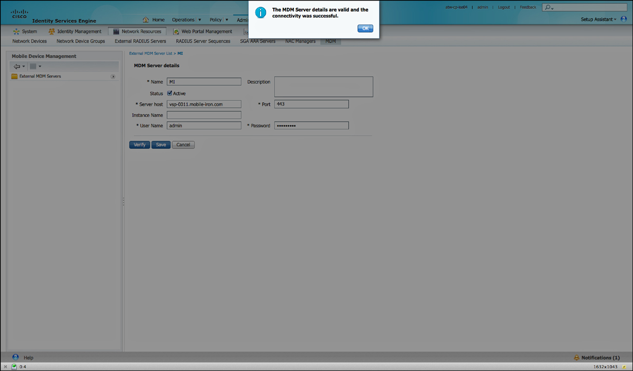
Now that the certificate is trusted, add the MDM Server to ISE. ISE may be configured with the knowledge of many MDMs, but only one may be active at a time:
4. Navigate to Administration > Network Resources > MDM.
5. Click Add.
6. Input a name for the connection to the MDM.
7. Add an optional description.
8. Input the hostname of the server.
9. The port should be 443, unless otherwise instructed by your MDM vendor.
10. Instance name is usually not used, but may be used in some cases when the vendor is multi-tenant aware.
11. Use the administrator name that will enroll all the mobile devices and its password.
12. Click Verify to test the connectivity.
13. Click Save.
Figure 17-63 shows the successful addition of the MDM.
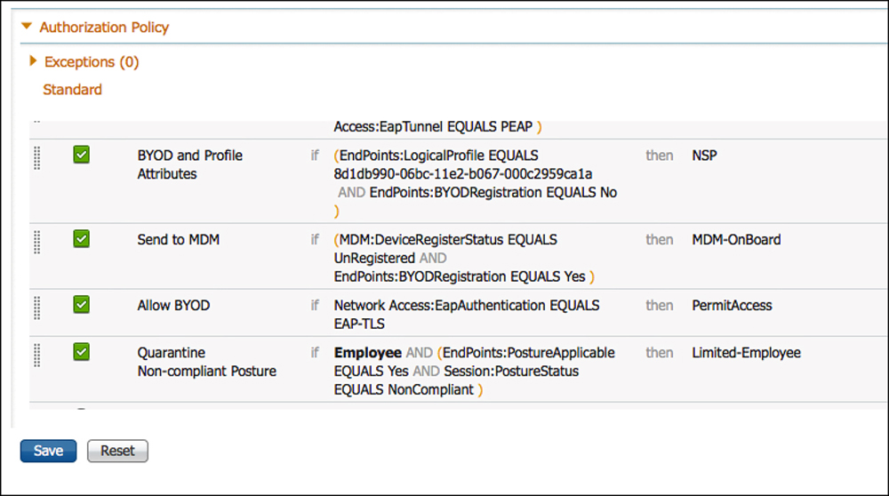
Configuring MDM Onboarding Policies
The MDM onboarding is configured much like the ISE BYOD onboarding. The authorization rules need to be configured to redirect the endpoint to MDM onboarding if it meets specific requirements.
One example of where to place an MDM onboarding policy is just below the BYOD onboarding rules, but above the rule that would permit final access. Some organizations would not want to send all devices to the MDM, but would prefer that specific devices be included. One way to achieve this is to maintain a separate list of MAC addresses belonging to corporate owned assets, and add that list to an endpoint identity group. The example shown in Figure 17-64 does not use identity groups, but it represents a policy that has been used in production at a number of installs.
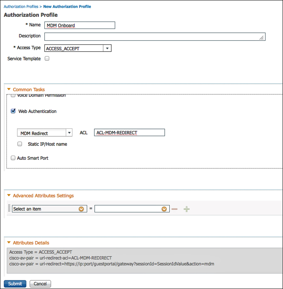
The first step is to create the authorization profile that redirects the endpoint to the MDM for onboarding:
1. Navigate to Policy > Policy Elements > Results > Authorization.
2. Select Authorization Profiles.
3. Add a new authorization profile named MDM Onboard.
4. Access type set to Access-Accept.
5. Set Web Authentication to MDM Redirect.
6. The Web Authentication ACL should reference an ACL that permits access to the MDM and ISE, but denies access to the rest of the Internet.
7. Click Submit.
Now, create an authorization rule to send devices to the MDM for onboarding:
1. Navigate to Policy > Authorization.
2. Insert a new rule where it makes sense in your policy.
3. Name the rule MDM Onboard.
4. Add the conditions, as follows:
Endpoints:BYODRegistration EQUALS Yes
And
MDM:DeviceRegistrationStatus EQUALS Unregistered
5. Set the result to the MDM Onboard Authorization Profile.
6. Click Done.
Add another rule below it that permits access to devices that are registered and meet the MDM Compliance:
7. Navigate to Policy > Authorization.
8. Insert a new rule below the MDM Onboard Rule.
9. Name the rule MDM Permit.
10. Add the conditions, as follows:
Endpoints:BYODRegistration EQUALS Yes
And
MDM:DeviceRegistrationStatus EQUALS Registered
And
MDM:DeviceComplianceStatus EQUAL Compliant
11. Set the Result to Permit Access.
12. Click Done.
13. Click Save.
When using MDM attributes as part of the authorization policy, ISE checks with the MDM at every authorization. So, if the MDM is unavailable, the rule will never match. There is also a bulk download of data from the MDM every four hours, detailing endpoint status. If an endpoint is marked non-compliant during that download, a CoA is sent and the device is forced to reauthenticate, providing a different result (such as quarantine).
Managing Endpoints
Each user may manage the devices they have personally onboarded from the My Devices portal, or the administrator may manage the devices from the endpoints screen.
Table 17-2 lists the options available with registered devices and provides a description of each option.

Self Management
The end users self-manage the devices they have registered via the MyDevices portal. Navigate to https://ISE:8443/mydevices/ or the friendly URL configured at Administration > Web Portal Management > Settings > General > Ports.
After logging in to the My Devices portal, the list of registered devices is displayed. As shown in Figure 17-66, the end user may select his device and initiate one of the options, such as Corporate Wipe.

Administrative Management
From an administrative perspective, the endpoints are administered just like any other endpoint at Administration > Identity Management > Identities > Endpoints. From here, an administrator may initiate actions against the registered devices, as shown in Figure 17-67.

You may also run a report to get a list of all registered devices and their current status (Operations > Reports > Endpoints and Users > Mobile Device Management Report). Figure 17-68 shows the MDM report with specific entries called out.

The Opposite of BYOD: Identify Corporate Systems
For many years, customers have voiced their business need to identify the machine as an authorized asset, in addition to the user being an authorized user. Given that Microsoft Windows has both a user and a machine state, it allows the device to be authenticated to the network with what is commonly known as machine auth, as well as the ability to have the interactive user authenticated to the network.
The issue is that EAP was always designed to transport a single credential. The machine authentication occurs when there is no interactive user or if the supplicant profile is configured to only issue the machine’s credentials. When the user logs into the system, it changes to a user-state and issues the credentials associated to the user. With standard RADIUS and standard EAP, there was no way to join those authentications together.
To answer the issue, Cisco enhanced EAP-FAST with the ability to do EAP chaining. EAP chaining is the ability to authenticate both the machine and the user within the same authentication session. EAP-FASTv2 is being standardized on and should be known as EAP-TEAP when it finalizes standardization.
EAP Chaining
With EAP-FASTv2 and EAP-chaining, both the machine and the user are issued a Protected Access Credential (PAC), similar to secure cookie. So, ISE may request the machine PAC during the user authentication process, and the authorization policy is capable of using the results of either or both authentications.
The authorization condition is NetworkAccess:EAPChainingResult, and the options are
![]() No chaining
No chaining
![]() User and machine both failed
User and machine both failed
![]() User and machine both succeeded
User and machine both succeeded
![]() User failed and machine succeeded
User failed and machine succeeded
![]() User succeeded and machine failed
User succeeded and machine failed
With that level of flexibility and authorization, a result may be provided that permits limited access to remediate a single failure, no access if neither succeeds, and full access if both succeed.
Figure 17-69 shows an example authorization rule that uses EAP chaining.

A practical example from a customer was to use EAP chaining to identify corporate owned and managed devices. The authorization rule acted like this:
If
the device and user authentication both succeed
and the endpoint posture is compliant
and the user is a member of the PCI group in Active Directory
and the location of the endpoint is on a corporate campus
Then
permit full access
and assign the PCI Security Group Tag (SGT)
That authorization rule allowed only those devices to communicate to the servers housing credit card data.
Summary
This chapter took an in-depth look at BYOD onboarding and MDM integration. It provided a brief look at identifying corporate assets and users with EAP chaining. The next chapter focuses on distributed ISE deployments.