Chapter 26. MACSec and NDAC
In years long passed, when WiFi was first being introduced into the consumer and corporate space, security concerns were raised. The concerns focused on sensitive data being transmitted through the air, without any level of confidentiality. The temporary answer to this was to use Wired Equivalency Protection (WEP). WEP was not very secure (as history has confirmed), but it provided an extra level of protection designed to bring wireless connections to the same security-level as a wired network.
Well, the fun part (for geeks like me) is that wireless networks quickly became even more secure than wired networks. As described many times in this book so far, 802.1X authentication took off like a rocket in wireless networks, and enhancements were made to the encryption and keying mechanisms (such as WiFi Protected Access [WPA/WPA2] using AES encryption). So, wireless networks had full encryption mechanisms to provide the confidentiality and integrity of data traversing the Layer 2 hop from the endpoint into the network infrastructure, in addition to the strong identity capabilities of 802.1X.
Wireless Equivalency was necessary for wired networks to provide equivalent confidentiality and integrity. What was the answer? Should IPSec be employed on every endpoint to every other endpoint, encrypting the entire communication from end-to-end? If that was done, how could you provide strong levels of quality of service (QoS) if you couldn’t see the content of a packet, and how could you glean into the packet to ensure security with all the Security tooling that you invested in? If you used end-to-end IPsec, you would simply be encrypting both good and bad traffic across the network.
The answer was to provide Wireless Equivalency. A viable alternative to end-to-end IPsec was to layer on the confidentiality and integrity using IEEE 802.1AE (a.k.a. MACSec). MACSec provides Layer 2 encryption on the LAN between endpoints and the switch, as well as between the switches themselves. Figure 26-1 provides a logical representation of MACSec.

MACSec
As described in this chapter’s introduction, MACSec (IEEE 802.1AE) provides Layer 2 encryption on the LAN. The encryption also encapsulates and protects the Cisco Meta Data (CMD) field, which carries the Security Group Tag (SGT), which is described in Chapter 25, “Secure Group Access.”
Currently, two keying mechanisms are available, both using 128-bit AES-GCM (Galois/Counter Mode) symmetric encryption that is capable of line-rate encryption and decryption for both 1Gb- and 10Gb-Ethernet interfaces and provides replay attack protection of each and every frame.
The keying mechanisms are Security Association Protocol (SAP) and MAC Security Key Agreement (MKA). SAP is a Cisco-proprietary keying protocol used between Cisco switches, while MKA is going to be the industry standard and is currently used between endpoints and Cisco switches.
Downlink MACSec
Downlink MACSec is the term used to describe the encrypted link between an endpoint and the switch. The encryption between the endpoint and the switch is handled by the MKA keying protocol. This requires a MACSec-capable switch (such as a Cisco Catalyst 3750-X), and a MACSec-capable supplicant on the endpoint (such as the Cisco AnyConnect Network Access Manager). The encryption on the endpoint may be handled in hardware (if the endpoint possesses the correct hardware) or in software using the main CPU for the encryption and decryption.
The Cisco switch has the ability to force encryption, make it optional, or force non-encryption; that setting may be configured manually per port (not common) or dynamically as an authorization result from ISE (more common). If ISE returns an encryption policy with the authorization result, the policy issued by ISE overrides anything set using the switch CLI.
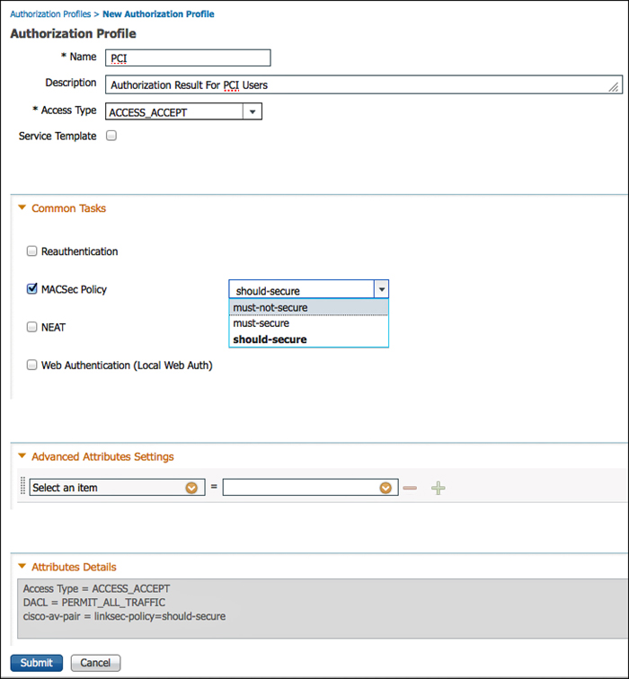
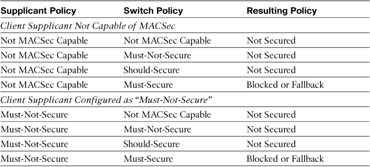
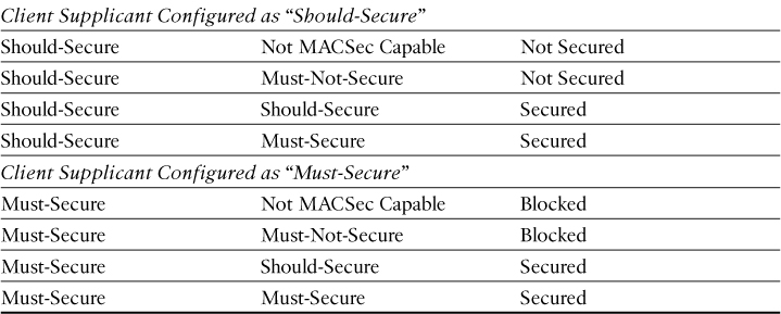
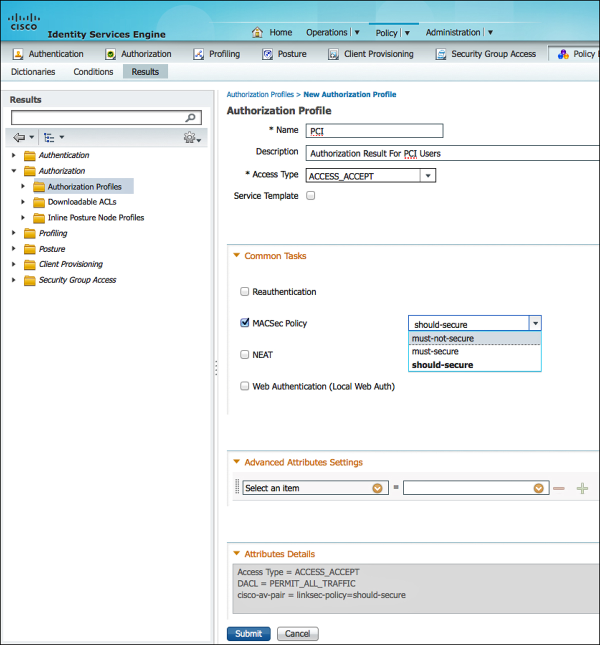
Figure 26-2 shows the MACSec Policy within an Authorization Profile on ISE. Notice at the bottom that the attribute sent to the switch is cisco-av-pair=subscriber:linksec-policy, followed by the policy itself. The choices are Must-Secure, Should-Secure, and Must-Not-Secure. Example 26-1 shows these options on the switch CLI, and Table 26-1 displays the resulting policy based on the Supplicant Policy and Switch Policy.
Example 26-1. MACSec Policy Switch CLI
C3750X(config-if)#authentication linksec policy ?
must-not-secure Never secure sessions
must-secure Always secure sessions
should-secure OPTIONALLY secure sessions
If the authentication server does not return the appropriate attribute-value pair to set the policy, the switch uses the configured policy on the port. If no policy is specified in the switch configuration, the switch reverts to the default policy of Should-Secure.
Switch Configuration Modes
Only a few configurations on the switch interface have implications for a MACSec deployment, such as the authentication host-mode. The host-mode plays an important role, because it determines the number of endpoints that may be connected to a single switch interface:
![]() Single Mode: MACSec is a fully supported in single-host-mode. In single-host-mode, only a single MAC or IP address can be authenticated and secured with MACSec. If a different MAC address is detected on the port after an endpoint has authenticated, a security violation will be triggered on the port.
Single Mode: MACSec is a fully supported in single-host-mode. In single-host-mode, only a single MAC or IP address can be authenticated and secured with MACSec. If a different MAC address is detected on the port after an endpoint has authenticated, a security violation will be triggered on the port.
![]() Multi-Domain Authentication (MDA) Mode: With this mode, a single endpoint may be on the Data domain, and another endpoint may be on the Voice domain. MACSec is fully supported in multi-domain authentication host mode. If both endpoints are MACSec capable, each is secured by its own independent MACSec session. If only one endpoint is MACSec capable, that endpoint is secured while the other endpoint sends traffic in the clear.
Multi-Domain Authentication (MDA) Mode: With this mode, a single endpoint may be on the Data domain, and another endpoint may be on the Voice domain. MACSec is fully supported in multi-domain authentication host mode. If both endpoints are MACSec capable, each is secured by its own independent MACSec session. If only one endpoint is MACSec capable, that endpoint is secured while the other endpoint sends traffic in the clear.
![]() Multi-Authentication Mode: With this mode, a virtually unlimited number of endpoints may be authenticated to a single switch port. MACSec is not supported in this mode.
Multi-Authentication Mode: With this mode, a virtually unlimited number of endpoints may be authenticated to a single switch port. MACSec is not supported in this mode.
![]() Multi-Host Mode: Although MACSec usage with this mode may technically be possible, it is not recommended. With Multi-Host Mode, the first endpoint on the port authenticates, and then any additional endpoints are permitted onto the network via the first authorization. So, MACSec works with the first connected host, but no other endpoint’s traffic actually passes, because it isn’t encrypted traffic.
Multi-Host Mode: Although MACSec usage with this mode may technically be possible, it is not recommended. With Multi-Host Mode, the first endpoint on the port authenticates, and then any additional endpoints are permitted onto the network via the first authorization. So, MACSec works with the first connected host, but no other endpoint’s traffic actually passes, because it isn’t encrypted traffic.
Example 26-2 shows a switch interface configuration for MACSec-enabled endpoints. The example uses the default MACSec policy of Should-Secure and, therefore, the default setting is not displayed.
Example 26-2. Switch Interface Configuration for MACSec
interface X
switchport access vlan 10
switchport mode access
switchport voice vlan 99
ip access-group ACL-ALLOW in
authentication event fail action next-method
authentication event server dead action authorize vlan 2274
authentication event server alive action reinitialize
authentication event linksec fail action next-method
authentication host-mode multi-domain
authentication open
authentication order dot1x mab
authentication priority dot1x mab
authentication port-control auto
authentication violation restrict
macsec
mka default-policy
mab
dot1x pae authenticator
dot1x timeout tx-period 10
spanning-tree portfast
end
ISE Configuration
Downlink MACSec is configured as attribute within the Authorization Profile (the result of an authorization). To add this result to an Authorization Profile, perform the following steps:
1. Navigate to Policy > Policy Elements > Results.
2. Choose Authorization Profiles.
3. Edit an Authorization Profile to which you want to add MACSec. (PCI was used in our example.)
4. Under Common Tasks, scroll to MACSec Policy.
5. Select must-secure, should-secure, or must-not-secure.
6. Click Submit or Save to save the change.
Figure 26-3 shows a MACSec policy being added to an Authorization Profile.
Uplink MACSec
Uplink MACSec describes encrypting the link between the switches with 802.1AE. At the time this book was written, the switch-to-switch encryption used Cisco’s proprietary Security Association Protocol (SAP) instead of MKA, which is used with the downlink MACSec. The encryption is still the same AES-GCM-128 encryption used with both Uplink and Downlink MACSec.
Uplink MACSec may be achieved manually or dynamically. Dynamic MACSec requires 802.1X between the switches and is covered in the section, “Network Device Admission Control (NDAC).” This section focuses on manual mode.
Manually Configuring Uplink MACSec
This method of MACSec is perfect to layer on top of the Manual SGT’s configured as part of Chapter 25. It encrypts the inter-switch links without requiring the entire domain of trust (the way that NDAC does). It also removes the dependency on ISE for the link keying, similar to how an IPSEC tunnel is built using pre-shared keys.
Let’s start by re-examining the configuration of your uplink interface as you had it configured at the end of Chapter 25.
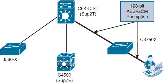
With the configuration shown in Example 26-3, the uplink between the 3750-X and the 6500-Sup2T is set up to use manual keying, without any encryption at all, to apply Security Group Tags (SGT) to the frames. Now, layer encryption on top of this to provide confidentiality and integrity of the SGTs and the data. Figure 26-4 depicts the relevant infrastructure configuration used for this example.
Example 26-3. Uplink Configuration from Chapter 25
C3750X# show run int Ten 1/1/1
Building configuration...
Current configuration : 286 bytes
!
interface TenGigabitEthernet1/1/1
description Cat6K Ten1/5
no switchport
ip address 10.1.48.2 255.255.255.252
ip authentication mode eigrp 1 md5
ip authentication key-chain eigrp 1 EIGRP
load-interval 60
cts manual
policy static sgt 2 trusted
no macro auto processing
end
The following steps guide you through adding encryption to the interface:
1. From interface configuration mode, enter cts manual.
2. Enable encryption with the sap pmk pairwise-master-key mode-list gcm-encrypt command.
The Pairwise Master Key (PMK) should be a hexadecimal value configured to be the same on both sides of the link. This master key can be compared to a RADIUS shared-secret between a NAD and ISE, or even the pre-shared key used with IPsec encryption. For the added security of dynamic keying, you must use NDAC.
3. Add the sap pmk pairwise-master-key mode-list gcm-encrypt command to the other side of the link.
Example 26-4 displays the example configuration steps, while Example 26-5 shows the final configuration for the uplink port on the 3750-X.
Example 26-4. Adding Encryption to the Uplink Interface
C3750X# conf t
Enter configuration commands, one per line. End with CNTL/Z.
C3750X(config)# int Ten1/1/1
C3750X(config-if)# cts manual
C3750X(config-if-cts-manual)# sap pmk 26 mode-list gcm-encrypt
C3750X(config-if-cts-manual)#end
C3750X#
Example 26-5. Final Configuration for Uplink Interface
C3750X#sho run int ten1/1/1
Building configuration...
Current configuration : 386 bytes
!
interface TenGigabitEthernet1/1/1
description Cat6K Ten1/5
no switchport
ip address 10.1.48.2 255.255.255.252
ip authentication mode eigrp 1 md5
ip authentication key-chain eigrp 1 EIGRP
load-interval 60
cts manual
policy static sgt 2 trusted
sap pmk 0000000000000000000000000000000000000000000000000000000000000026 mode-list
gcm-encrypt
no macro auto processing
end
Verifying the Manual Configuration
Validate that the manual encryption on the uplink was successful with the show cts interface command, as shown in Example 26-6. SAP status is the status of the encryption; in the example, notice that SAP succeeded, the pairwise cypher is using gcm-encrypt, and that replay protection is enabled.
Example 26-6. Output of show cts interface Command
C3750X#show cts interface TenGigabitEthernet 1/1/1
Global Dot1x feature is Enabled
Interface TenGigabitEthernet1/1/1:
CTS is enabled, mode: MANUAL
IFC state: OPEN
Authentication Status: NOT APPLICABLE
Peer identity: "unknown"
Peer's advertised capabilities: "sap"
Authorization Status: SUCCEEDED
Peer SGT: 2
Peer SGT assignment: Trusted
SAP Status: SUCCEEDED
Version: 2
Configured pairwise ciphers:
gcm-encrypt
Replay protection: enabled
Replay protection mode: STRICT
Selected cipher: gcm-encrypt
Propagate SGT: Enabled
Cache Info:
Cache applied to link : NONE
Statistics:
authc success: 0
authc reject: 0
authc failure: 0
authc no response: 0
authc logoff: 0
sap success: 2
sap fail: 0
authz success: 5
authz fail: 0
port auth fail: 0
L3 IPM: disabled.
C3750X#
As you can see from this section, there is not much configuration necessary to use manual Uplink MACSec, assuming that you are using MACSec-capable hardware. However, there is still this concept of a “domain of trust” with the Secure Access solution—where you can authenticate and authorize any network devices before they participate in your infrastructure. To examine that domain of trust further, let’s discuss Network Device Admission Control (NDAC).
Network Device Admission Control
The Secure Unified Access architecture builds secure networks by establishing domains of trusted network devices. The days of someone grabbing a rogue off-the-shelf switch and connecting it to your enterprise network infrastructure and possibly wreaking havoc are a thing of the past.
For a network device to be part of the network infrastructure and pass traffic, its peer(s) must first authenticate it. You are authenticating the switch via 802.1X, much like you are now authenticating the endpoints and users with 802.1X. However, once the device is allowed to join the network infrastructure, the communication on the links between devices is secured with MACSec. This process is known as Network Device Admission Control (NDAC).
There are three main roles within NDAC:
![]() Supplicant: The role of an unauthenticated switch connected to a peer within the trusted domain, and attempting to join that domain.
Supplicant: The role of an unauthenticated switch connected to a peer within the trusted domain, and attempting to join that domain.
![]() Authentication server: The server that validates the identity of the supplicant and issues the policies to allow the device onto the network as well as being responsible for the encryption keys. This is the Cisco ISE server.
Authentication server: The server that validates the identity of the supplicant and issues the policies to allow the device onto the network as well as being responsible for the encryption keys. This is the Cisco ISE server.
![]() Authenticator: An authenticated device that is already part of the trusted domain and can authenticate new peer supplicants on behalf of authentication server.
Authenticator: An authenticated device that is already part of the trusted domain and can authenticate new peer supplicants on behalf of authentication server.
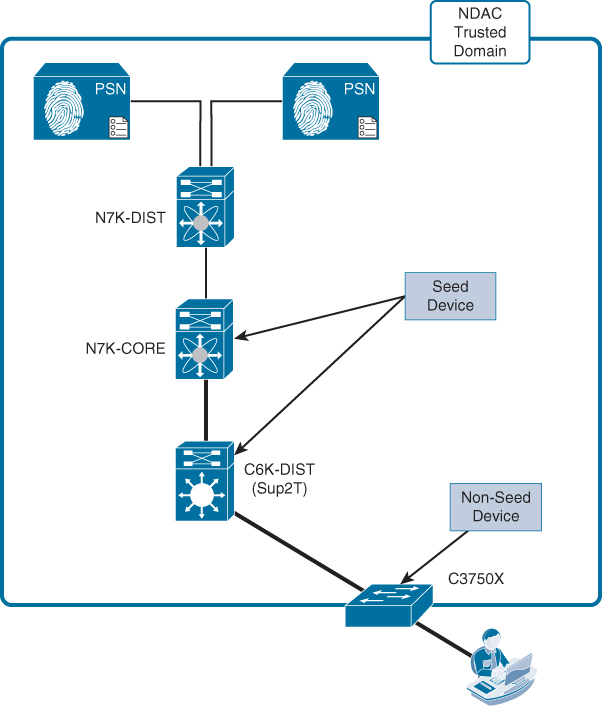
There is another role: seed device. There must be at least one seed device. This device has knowledge of at least one ISE Policy Service Node. The seed device begins or creates the NDAC-trusted domain. When a new switch is added to the network, a switch that’s already a member of the NDAC domain authenticates it, as shown in Figure 26-5.

Creating an NDAC Domain
An NDAC domain is created when the first switch (known as the seed device) is authenticated and authorized by ISE.
Configuring ISE
The following steps prepare ISE for NDAC and SGA.
Perform the following steps from the ISE GUI:
1. Navigate to Administration > Network Resources > Network Device Groups.
2. Add a new Top-Level Device Group.
3. Name the Group and the Type SGA.
4. Create a new NDG named SGA-Device; the type should be SGA.
5. Create a new NDG named Non-SGA-Device; the type should be SGA.
Figure 26-6 shows the final Network Device Groups.

Now, add the switch to ISE as a NAD. This procedure may have been completed during Chapter 25; however, go through the screens in ISE and ensure it all configured correctly.
From the ISE GUI, perform the following steps:
1. Navigate to Administration > Network Resources > Network Devices.
2. If the switch is already in the device list, edit it. If not, add a new device.
3. Ensure that the RADIUS shared secret is configured.
4. Set the Network Device Groups. Specifically, assign the NAD to the SGA-Device NDG.
5. Enable the Advanced TrustSec Settings section of the NAD definition.
6. Here, you may use either the device-id for SGA Identification or configure a new name.
Note
This name must match what you configure on the switch in later steps.
7. The Device Configuration Deployment section allows ISE to push SGT-to-IP mappings to the switch. This is optional, but if you want that functionality, add the exec and enable passwords.
8. Click Save.
9. Repeat Steps 1 through 8 for all network devices that participate in the NDAC trusted domain.
Figure 26-7 displays the completed Advanced TrustSec settings for a Nexus switch.
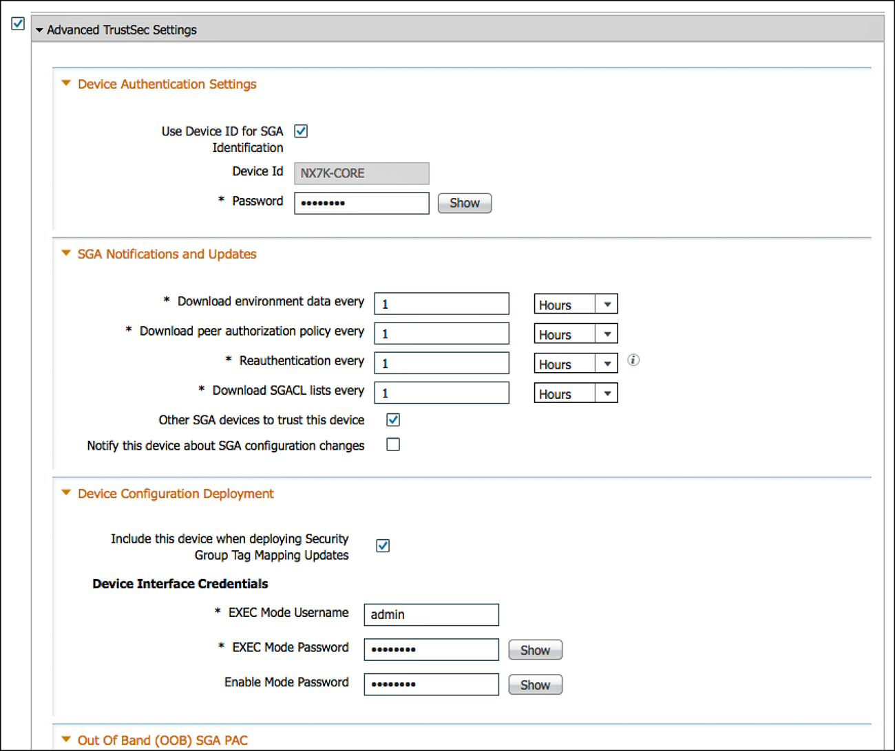
Once you submit a network device with the Advanced TrustSec Settings configured, the device name and password are added to a special internal identity store, known as Internal CTS Devices. This identity store is what will be used for the NDAC authentications.
The big difference between seed and non-seed devices is whether the device is configured with the list of AAA servers for NDAC. Instead, it gets the list of AAA servers from the seed device. To build the list of AAA servers to be sent to non-seed devices, add it to the SGA AAA Servers list within ISE:
1. Navigate to Administration > Network Resources > SGA AAA Servers.
2. Click Add.
3. Enter the PSN name.
4. Enter the PSN IP address.
5. Click Submit.
6. Repeat Steps 2 through 5 for all PSNs that will be involved with NDAC.
Figure 26-8 shows an example list of two AAA servers to be sent to the non-seed devices.

Create a Network Authorization Policy for the switches to be assigned an SGT and permitted to join the NDAC Trusted Domain:
1. Navigate to Policy > Security Group Access > Network Device Authorization.
2. Insert a rule above the default rule.
3. Name the rule SGA Devices.
4. Set the condition to be SGA equals SGA-Device. This is using the Network Device Group you created earlier in this chapter.
5. Set the resulting security group to be the NADs group created in Chapter 25 (SGT = 2).
6. Click Done.
7. Click Save.
Figure 26-9 shows a simple NDAC policy.

Configuring the Seed Device
Now that ISE is prepared, it is time to configure the first switch of the NDAC trusted domain, the seed device. For this example, let’s use the Nexus core switch as the seed device, shown in Figure 26-5. All switches may be configured as seed devices, if that is your choice.
From the switch CLI, perform the following steps:
1. Enter show dot1x to see if the feature is enabled from Chapter 25. If it is not, type feature dot1x from global configuration mode.
2. Enter show cts and validate that the feature is enabled from Chapter 25. If not, type feature cts from global configuration mode.
3. Set the CTS device-id at global configuration mode using the cts device-id device-id password password command.
Note
This device-id and password must match exactly what was configured in the network device definition within ISE.
4. Add ISE to the configuration with the radius-server host ip-address key shared-secret pac.
Note
The pac keyword is used to configure the Nexus switch to download a Protected Access Credential (PAC) that will be used to secure the RADIUS transactions.
5. Repeat Step 4 for all applicable RADIUS servers.
6. Create a RADIUS server group with the aaa group server radius group-name command.
7. Add the servers to the group with the server ip-address command.
8. Repeat Step 7 for all applicable servers.
9. Configure the RADIUS server group to use the correct VRF with the use-vrf vrf-name command.
10. Configure AAA authentication for 802.1X with the aaa authentication dot1x default group radius-group-name command.
11. Configure AAA accounting for 802.1X with the aaa accounting dot1x default group radius-group-name command.
12. Configure CTS authorization for 802.1X with the aaa authorization cts default group radius-group-name command.
13. Re-enter the cts device-id device-id password password command to trigger an immediate download of the PAC file.
Example 26-7 shows an example configuration on the Nexus 7000 Core switch.
Example 26-7. Configuring the Nexus 7000 Seed Device
NX7K-CORE(config)# cts device-id NX7K-CORE password Cisco123
NX7K-CORE(config)# radius-server host 10.1.103.4 key Cisco123 pac
NX7K-CORE(config)# radius-server host 10.1.103.3 key Cisco123 pac
NX7K-CORE(config)# aaa group server radius ise
NX7K-CORE(config-radius)# server 10.1.103.4
NX7K-CORE(config-radius)# server 10.1.103.3
NX7K-CORE(config-radius)# use-vrf default
NX7K-CORE(config)# aaa authentication dot1x default group ise
NX7K-CORE(config)# aaa accounting dot1x default group ise
NX7K-CORE(config)# aaa authorization cts default group ise
NX7K-CORE(config)# cts device-id NX7K-CORE password Cisco123
NX7K-CORE(config)#
NX7K-CORE(config)# sho cts pac
PAC Info :
==============================
PAC Type : Trustsec
AID : 01ecb966907841dd6af9cfdc810c3d4e
I-ID : NX7K-CORE
AID Info : Identity Services Engine
Credential Lifetime : Wed Mar 27 14:51:01 2013
PAC Opaque : 000200b8000300010004001001ecb966907841dd6af9cfdc810c3d4e
0006009c00030100eb281feae6759891966c609335bb71930000001350d502f300093a805f1acdce
863015e76decbd96e98d628146738491ef414d34d5c4685d09fdec04dbfbb46ebee17174e4b75403
a10e29014032189c3c1cba408261f5862dbaee1e9c275bcc264267bdce1333baeaa370aa7e49f97e
0c353b620badb4ca00a185af6fb1b7e0c5a12407c7ecfd2284f2aa50e168640040eeefe8ca9c4e7d
NX7K-CORE(config)#
NX7K-CORE(config)# sho cts environment-data
CTS Environment Data
==============================
Current State : CTS_ENV_DNLD_ST_ENV_DOWNLOAD_DONE
Last Status : CTS_ENV_SUCCESS
Local Device SGT : 0x0002
Transport Type : CTS_ENV_TRANSPORT_DIRECT
Data loaded from cache : FALSE
Env Data Lifetime : 600 seconds after last update
Last Update Time : Thu Dec 27 14:09:43 2012
Server List : CTSServerList1
AID:01ecb966907841dd6af9cfdc810c3d4e IP:10.1.103.4 Port:1812
AID:01ecb966907841dd6af9cfdc810c3d4e IP:10.1.103.3 Port:1812
Example 26-8 shows an example configuration on the Catalyst 6500 Sup2T Distribution switch.
Example 26-8. Configuration of a Catalyst 6500 Seed Device
C6K-DIST# cts credentials id C6K-DIST password Cisco123
CTS device ID and password have been inserted in the local keystore.
Please make sure that the same ID and password are configured in the
server database.
C6K-DIST(config)# cts authorization list default
C6K-DIST(config)# radius-server host 10.1.103.3 auth-port 1812 acct-
port 1813 test username radius-test pac key Cisco123
Request successfully sent to PAC Provisioning driver.
C6K-DIST(config)# radius-server host 10.1.103.4 auth-port 1812 acct-
port 1813 test username radius-test pac key Cisco123
Request successfully sent to PAC Provisioning driver.
Note: the pac keyword in the radius-server configuration is
essential, to ensure the RADIUS communication between the switch and
ISE is secured for NDAC.
C6K-DIST(config)# radius-server vsa send authentication ! (this will
most likely be configured already)
C6K-DIST(config)# dot1x system-auth-control ! (this will most likely be
configured already)
Adding Non-Seed Switches
A non-seed device does not have a configuration to locate the AAA servers to use with NDAC. Instead, the list is downloaded from the seed device. However, the device still needs to be added to ISE as a network device, which was accomplished in an earlier procedure.
It is not required to use any non-seed devices, but it is a viable option and, therefore, is covered in this chapter. For these examples, let’s configure the 3750X as a non-seed device, and all other switches will be configured as seed devices.
Figure 26-10 displays the example NDAC environment.
The majority of the configuration required to be a non-seed device has been accomplished when bootstrapping the device to work with ISE in Chapter 11, “Bootstrapping Network Access Devices.”
The CTS credentials must be entered into the device, just as with the seed device, as shown in Example 26-9.
Example 26-9. 3750-X Non-Seed Device Configuration
C3750X#cts credentials id C3750X password Cisco123
CTS device ID and password have been inserted in the local keystore.
Please make sure that the same ID and password are configured in the
server database.
The next set of commands should already be configured in the switch from Chapter 11:
C3750X(config)# aaa new-model
C3750X(config)# aaa authentication dot1x default group radius
C3750X(config)# aaa authorization network default group radius
C3750X(config)# aaa accounting dot1x default start-stop group radius
C3750X(config)# radius-server vsa send authentication
C3750X(config)# dot1x system-auth-control
Configuring the Switch Interfaces for Both Seed and Non-Seed
Once the global configuration is complete, all that is truly needed for the switch interfaces is to enter the cts dot1x command on the interfaces that are to be trusted in NDAC, as shown in Example 26-10.
Example 26-10. Enabling NDAC on the Interface
C3750X(config)# int Ten1/1/1
C3750X(config-if)# cts dot1x
C3750X(config-if-cts-dot1x)#
To verify the interface activities, use the show cts interface interface-name command as shown in Example 26-11.
Example 26-11. Verifying Interface Activities with show cts interface
C6K-DIST#sho cts interface
Global Dot1x feature is Enabled
Interface TenGigabitEthernet1/5:
CTS is enabled, mode: DOT1X
IFC state: OPEN
Authentication Status: SUCCEEDED
Peer identity: "C3750X"
Peer's advertised capabilities: "sap"
802.1X role: Authenticator
Reauth period configured: 86400 (default)
Reauth period per policy: 86400 (server configured)
Reauth period applied to link: 86400 (server configured)
Reauth starts in approx. 0:14:11:09 (dd:hr:mm:sec)
Authorization Status: SUCCEEDED
Peer SGT: 2:NADs
Peer SGT assignment: Trusted
SAP Status: SUCCEEDED
Version: 2
Configured pairwise ciphers:
gcm-encrypt
null
Replay protection: enabled
Replay protection mode: STRICT
Selected cipher: gcm-encrypt
Propagate SGT: Enabled
Cache Info:
Cache applied to link : NONE
Statistics:
authc success: 4890
authc reject: 40
authc failure: 11
authc no response: 0
authc logoff: 31
sap success: 2
sap fail: 0
authz success: 19
authz fail: 4871
port auth fail: 0
L3 IPM: disabled.
Dot1x Info for TenGigabitEthernet1/5
-----------------------------------
PAE = AUTHENTICATOR
QuietPeriod = 60
ServerTimeout = 0
SuppTimeout = 30
ReAuthMax = 2
MaxReq = 2
TxPeriod = 30
MACSec Sequence in an NDAC Domain
When the link between a supplicant and an authenticator first appears, the following sequence of events typically occurs:
1. Authentication: Using Network Device Admission Control (NDAC), ISE authenticates a device using EAP-FAST before allowing it to join the network. During the EAP-FAST exchange, ISE creates and sends a unique protected access credential (PAC) to the supplicant switch (the switch attempting to join the NDAC domain). That PAC contains a shared key and an encrypted token for future secure communications with the authentication server.
2. Authorization: Based on the identity information of the supplicant switch, ISE provides authorization policies to each of the linked peers. The authentication server provides the identity of each peer to the other, and each peer then applies the appropriate policy for the link.
3. SAP negotiation: When both sides of a link support encryption, the supplicant and the authenticator negotiate the necessary parameters to establish a security association (SA) and encrypt the traffic.
4. When all three steps are complete, the authenticator changes the state of the link from the unauthorized (blocking) state to the authorized state, and the supplicant switch becomes a member of the NDAC trusted domain.
Summary
In Chapter 25, you learned about Security Group Access (SGA) and the ability to apply a tag to traffic based on the contextual identity of the endpoint or user; you also learned how to apply this traffic manually, and without the inherent security associated with a domain of trusted devices, using strong encryption between them.
In this chapter, you learned about Network Device Admission Control (NDAC) and IEEE 802.1AE (MACSec), where all the Cisco devices in the network are authorized before being added to the network, and all devices can form a trusted domain, which encrypts all traffic (including the SGT) across network links between those trusted devices.
Chapter 27, “Network Edge Access Topology,” briefly focuses on another addition to this trusted-domain approach, meant for conference rooms where wired connectivity is a requirement. This technology is known as Network Edge Access Topology (NEAT).