
Chapter 3. Configuring Cisco ASA with FirePOWER Services
This chapter provides step-by-step guidance on how to set up and configure the Cisco ASA with FirePOWER Services module. The following topics are covered in this chapter:
![]() Setting up the Cisco ASA FirePOWER module in Cisco ASA 5585-X appliances
Setting up the Cisco ASA FirePOWER module in Cisco ASA 5585-X appliances
![]() Setting up the Cisco ASA FirePOWER module in Cisco ASA 5500-X appliances
Setting up the Cisco ASA FirePOWER module in Cisco ASA 5500-X appliances
![]() Configuring the Cisco ASA to redirect traffic to the Cisco ASA FirePOWER module
Configuring the Cisco ASA to redirect traffic to the Cisco ASA FirePOWER module
![]() Configuring the Cisco ASA FirePOWER services module for the FMC
Configuring the Cisco ASA FirePOWER services module for the FMC
![]() Configuring the Cisco ASA FirePOWER module using the Adaptive Security Device Manager (ASDM)
Configuring the Cisco ASA FirePOWER module using the Adaptive Security Device Manager (ASDM)
![]() Firepower Threat Defense (FTD)
Firepower Threat Defense (FTD)
Setting Up the Cisco ASA FirePOWER Module in Cisco ASA 5585-X Appliances
In Chapter 2, “Introduction to and Design of Cisco ASA with FirePOWER Services,” you learned that in the Cisco ASA 5585-X, the Cisco ASA FirePOWER module includes a separate management interface. All management traffic to and from the Cisco ASA FirePOWER module must enter and exit this interface. You also learned that the Cisco ASA FirePOWER module needs Internet access to perform several operations.
Figure 3-1 shows an example of how you can physically connect the Cisco ASA FirePOWER module management interface to be able to reach the Internet by using the Cisco ASA interface.

Figure 3-1 shows the Cisco ASA 5585-X with a module running Cisco ASA software and a module running FirePOWER Services. The Cisco ASA software is managed by using the interface named Management 0/0 in this example. This interface is configured with the IP address 10.10.1.1. The Cisco ASA FirePOWER module is managed by using the interface named Management 1/0, configured with the IP address 10.10.1.2.
You can access the Cisco ASA FirePOWER module command-line interface (CLI) by using the serial console port or Secure Shell (SSH).
Cisco ASA 5585-X appliances have a dedicated console port for the Cisco ASA FirePOWER module. You can use a DB-9 to RJ-45 serial cable or a USB serial adapter to connect to the console.
Note
In all other Cisco ASA models, you connect to the Cisco ASA console and then you connect by using the backplane to the “module” or solid state drive (SSD) by using the session sfr command. The Cisco ASA 5506-X, Cisco ASA 5508-X, and Cisco ASA 5516-X also come with a mini-USB console port that you can use.
You can also connect to the Cisco ASA FirePOWER module by using SSH, with the default IP address.
Table 3-1 lists all the default parameters and credentials of the Cisco ASA FirePOWER module.

Installing the Boot Image and Firepower System Software in the Cisco ASA 5585-X SSP
In order to have a fully functional Cisco ASA FirePOWER module in a Cisco ASA 5585-X, the boot image needs to first be installed, and then a system software package needs to be installed as well.
Note
If you purchased a new Cisco ASA with FirePOWER Services, you do not need to reimage the system to install upgrade packages.
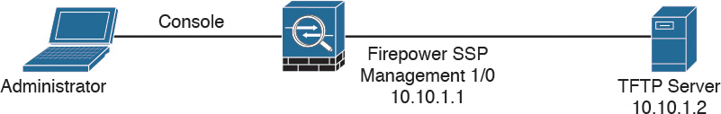
To install the boot image, you need to transfer the image from a TFTP server to the Management-0 port on the ASA Firepower SSP by logging in to the module’s Console port.
Tip
The Management-0 port is in the first slot on an SSP. This management port is also known as Management 1/0; however, it appears as Management-0 or Management 0/1 in ROMMON.
Figure 3-2 illustrates a topology with a Cisco ASA with a Firepower SSP and a TFTP server. The Cisco ASA Firepower SSP management interface is configured with IP address 10.10.1.1 and the TFTP server with 10.10.1.2.
Follow these steps to install the boot image:
Step 1. Place the boot image and a system software package on the TFTP server so that they can be accessed by the Cisco ASA FirePOWER module.
Step 2. Connect to the Cisco ASA FirePOWER module through the Management 1/0 interface. You must use this interface to TFTP boot the boot image.
Step 3. Reboot the system with the system reboot command.
Step 4. As the system is booting, break out of the boot process by pressing Esc (the Escape key on your keyboard). If you see grub start to boot the system, you are too late, and you have to reboot the system again.
Step 5. From the ROMMON prompt, configure the IP address for the Firepower SSP, the TFTP server address, the gateway, and the boot image path and filename. The following example shows the configuration used in this example:
ADDRESS=10.10.1.1
SERVER=10.10.1.2
GATEWAY=10.1.1.2
IMAGE= asasfr-5500x-boot-6.0.0-1005.img
In this example, the IP address of the Firepower SSP is 10.10.1.1. The TFTP server address is 10.10.1.2, and the gateway is set to the TFTP server address, as well. The boot image is asasfr-5500x-boot-6.0.0-1005.img. After entering the preceding commands, issue the set command to apply the configuration.
Step 6. Save the settings by using the sync command.
Step 7. Start the download and boot process by using the tftp command.
Note
The boot takes several minutes. When it is finished, you see a login prompt.
Step 8. Log in as admin, with the password Admin123, which is the default password.
Step 9. Start configuring the system by issuing the setup command.
Step 10. Configure the hostname, which can be up to 65 alphanumeric characters, with no spaces (though hyphens are allowed).
Step 11. Configure the IP address. You can configure a static IPv4 or IPv6 address or use DHCP (for IPv4) or stateless autoconfiguration if you are configuring IPv6.
Step 12. Identify at least one DNS server and set the domain name and search domain.
The management address, the gateway, and DNS information are the key settings to configure. Administrators often forget to set up the DNS server correctly, and this causes problems later in the configuration.
Step 13. Optionally, enable NTP and configure the NTP servers to set the system time.
Step 14. Install the system software image by using the system install [noconfirm] url command. Here is an example:
asasfr-boot> system install http://10.10.1.2/ asasfr-sys-6.0.0-1005.pkg
Note
The noconfirm option skips all the confirmation messages.
The Cisco ASA FirePOWER module reboots when the installation is complete. This process can take more than 10 minutes. After the Cisco ASA FirePOWER module boots, you can log in as admin with the password Sourcefire. You can install the system software image from an HTTP, HTTPS, or FTP server that is accessible from the ASA SFR management interface.
Note
Detailed step-by-step configuration options are provided later in this chapter.
Setting Up the Cisco ASA FirePOWER Module in Cisco ASA 5500-X Appliances
The following sections cover how to perform the initial setup of the Cisco ASA FirePOWER module in Cisco ASA 5500-X appliances.
Tip
Cisco is always adding new models to its next-generation security appliances. Visit Cisco’s Firepower compatibility guide to obtain the most recent information: www.cisco.com/c/en/us/td/docs/security/firepower/compatibility/firepower-compatibility.html.
Installing the Boot Image and Firepower System Software in the SSD of Cisco ASA 5500-X Appliances
As you have already learned in this chapter, if you purchase a new Cisco ASA 5500-X appliance with the Cisco ASA FirePOWER module, the module software and required SSDs come preinstalled and ready to configure. However, you need to install the Cisco ASA Firepower boot software, partition the SSD, and install the system software if you are adding a new Cisco ASA FirePOWER software module to an existing Cisco ASA or if the SSD needs to be replaced.
Tip
The flash (disk0) should have at least 3 GB of free space plus the space needed for the boot software in order to perform the reimaging process. If you are running the Cisco ASA in multi-context mode, you need to complete the reimaging steps in the system execution space. You also need to shut down any other modules from the Cisco ASA CLI, as shown in Example 3-1.
Example 3-1 Shutting Down and Uninstalling the IPS Module
sw-module module ips shutdown
sw-module module ips uninstall
reload
The commands in Example 3-1 shut down and uninstall the IPS software module (if installed on the Cisco ASA) and reboot the Cisco ASA. If you have a Cisco ASA CX module, you can use the same commands except use the cxsc keyword instead of ips.
Note
If you are just reimaging the Cisco ASA FirePOWER module, use the sw-module module sfr shutdown and sw-module module sfr uninstall commands.
Complete the following steps to install the boot image and the Firepower system software in the SSD of a Cisco ASA 5500-X appliance:
Step 1. Download the Firepower boot image and system software packages from Cisco.com.
Step 2. Transfer the boot image to the ASA. You can do this by using the CLI or the ASDM. If you select to install the image by using the ASDM, you can place the boot image on your workstation and upload it from there or you can place it on an FTP, TFTP, HTTP, HTTPS, SMB, or SCP server. In the ASDM, select Tools > File Management and choose the appropriate file transfer command, either Between Local PC and Flash or Between Remote Server and Flash. Figure 3-3 illustrates how to transfer the file between the remote server and flash.

If you choose to transfer the file by using the CLI, place the boot image on a TFTP, FTP, HTTP, or HTTPS server and then use the copy command to transfer it to the Cisco ASA flash. To transfer the file by using TFTP, enter the following command:
RTP-asa# copy tftp://10.10.1.2/asasfr-5500x-boot-5.4.1-69.img
disk0:/asasfr-5500x-boot-5.4.1-69.img
Step 3. Transfer the boot software to disk0 on the ASA.
Step 4. After the boot image is transferred to disk0 (flash), use sw-module module sfr recover configure image disk0: file to recover the Firepower module and install the boot image, as demonstrated here:
NY-asa# sw-module module sfr recover configure image
disk0:asasfr-5500x-boot-5.4.1-69.img
Step 5. Use the sw-module module sfr recover boot command to load the Firepower boot image. This takes approximately 5 to 15 minutes.
Step 6. Use the session command to connect to the Firepower module from the Cisco ASA, as demonstrated in the example that follows. The default username is admin, and the default password is Admin123:
RTP-asa# session sfr console
Opening console session with module sfr.
Connected to module sfr. Escape character sequence is 'CTRL-^X'.
Cisco ASA SFR Boot Image 5.4.1
asasfr login: admin
Password: Admin123
Note
The session command fails with a message about not being able to connect over ttyS1 if the module has not completed the boot process.
Step 7. Configure the module so that you can install the system software package using the setup command, as shown here:
asasfr-boot> setup
Welcome to SFR Setup
[hit Ctrl-C to abort]
Default values are inside []
Enter the hostname, management address, gateway, DNS information, and, optionally, NTP server. It is very important to enter a correct DNS server to avoid name resolution problems during setup. You can also set the domain name and search domain.
Step 8. Install the system software image by using the system install [noconfirm] url command. You can transfer the file using HTTP, HTTPS, or FTP. The following example demonstrates how to install the system software image by using HTTP:
asasfr-boot> system install http://10.10.1.3/asasfr-sys-5.4.1-211.pkg
Verifying
Downloading
Extracting
Package Detail
Description: Cisco ASA-Firepower 5.4.1-211
System Install
Requires reboot: Yes
Do you want to continue with upgrade? [y]: y
Warning: Please do not interrupt the process or turn off the system.
Doing so might leave system in unusable state.
Upgrading
Starting upgrade process ...
Populating new system image
Reboot is required to complete the upgrade. Press 'Enter' to reboot the system.
(press Enter)
Broadcast message from root (ttyS1) (Mon Sep 28 12:12:48 2015):
The system is going down for reboot NOW!
Console session with module sfr terminated.
When the Firepower module reboots and you use the session command to access the module, you see a different login prompt, as shown in Example 3-2.
Example 3-2 A Functional Firepower Module
RTP-asa# session sfr console
Opening console session with module sfr.
Connected to module sfr. Escape character sequence is 'CTRL-^X'.
RTP-sfr login: admin
Password:
Last login: Sun Sep 27 02:02:28 UTC 2015 on ttyS1
Copyright 2001-2013, Sourcefire, Inc. All rights reserved. Sourcefire is
a registered trademark of Sourcefire, Inc. All other trademarks are
property of their respective owners.
Sourcefire Linux OS v5.4.1 (build 43)
Sourcefire ASA5512 v5.4.1 (build 211)
Last login: Sun Sep 27 02:02:28 on ttyS1
>
Configuring of Cisco ASA 5506-X, 5508-X, and 5516-X Appliances
When the Cisco ASA is booted with no configuration, it offers a setup menu that enables you to assign the initial parameters, such as the device name and an address for the management interface. You can choose to go through the initial setup menu for quick configuration. Example 3-3 shows the boot process (console output) for an ASA 5508.
Example 3-3 Boot Process of the ASA 5508
Rom image verified correctly
Cisco Systems ROMMON, Version 1.1.01, RELEASE SOFTWARE
Copyright (c) 1994-2014 by Cisco Systems, Inc.
Compiled Mon 10/20/2014 15:59:12.05 by builder
Current image running: Boot ROM0
Last reset cause: PowerCycleRequest
DIMM Slot 0 : Present
DIMM Slot 1 : Present
Platform ASA5508 with 8192 Mbytes of main memory
MAC Address: 18:8b:9d:ad:79:c1
Use BREAK or ESC to interrupt boot.
Use SPACE to begin boot immediately.
Boot in 10 seconds.
Located '.boot_string' @ cluster 840607.
#
Attempt autoboot: "boot disk0:/asa951-lfbff-k8.SPA"
Located 'asa951-lfbff-k8.SPA' @ cluster 816328.
####################################################################################
##################################################################################
##################################################################################
##################################################################################
##################################################################################
##################################################################################
##################################################################################
##################################################################################
####################################################################
LFBFF signature verified.
INIT: version 2.88 booting
Starting udev
Configuring network interfaces... done.
Populating dev cache
dosfsck 2.11, 12 Mar 2005, FAT32, LFN
There are differences between boot sector and its backup.
Differences: (offset:original/backup)
65:01/00
Not automatically fixing this.
Starting check/repair pass.
Starting verification pass.
/dev/sdb1: 120 files, 838432/1918808 clusters
dosfsck(/dev/sdb1) returned 0
Processor memory 3754858905
Compiled on Wed 12-Aug-15 12:18 PDT by builders
Total NICs found: 13
i354 rev03 Gigabit Ethernet @ irq255 dev 20 index 08 MAC: 188b.9dad.79c1
ivshmem rev03 Backplane Data Interface @ index 09 MAC: 0000.0001.0002
en_vtun rev00 Backplane Control Interface @ index 10 MAC: 0000.0001.0001
en_vtun rev00 Backplane Int-Mgmt Interface @ index 11 MAC: 0000.0001.0003
en_vtun rev00 Backplane Ext-Mgmt Interface @ index 12 MAC: 0000.0000.0000
Verify the activation-key, it might take a while...
Running Permanent Activation Key: 0x7007c269 0x1098868c 0x54928558 0xa9987ca0
0x081c04af
Licensed features for this platform:
Maximum Physical Interfaces : Unlimited perpetual
Maximum VLANs : 50 perpetual
Inside Hosts : Unlimited perpetual
Failover : Active/Active perpetual
Encryption-DES : Enabled perpetual
Encryption-3DES-AES : Enabled perpetual
Security Contexts : 2 perpetual
GTP/GPRS : Disabled perpetual
AnyConnect Premium Peers : 4 perpetual
AnyConnect Essentials : Disabled perpetual
Other VPN Peers : 100 perpetual
Total VPN Peers : 100 perpetual
Shared License : Disabled perpetual
AnyConnect for Mobile : Disabled perpetual
AnyConnect for Cisco VPN Phone : Disabled perpetual
Advanced Endpoint Assessment : Disabled perpetual
Total UC Proxy Sessions : 320 perpetual
Botnet Traffic Filter : Disabled perpetual
Cluster : Disabled perpetual
VPN Load Balancing : Enabled perpetual
Encryption hardware device : Cisco ASA Crypto on-board accelerator (revision 0x1)
Cisco Adaptive Cisco ASA Software Version 9.5(1)
****************************** Warning *******************************
This product contains cryptographic features and is
subject to United States and local country laws
governing, import, export, transfer, and use.
Delivery of Cisco cryptographic products does not
imply third-party authority to import, export,
distribute, or use encryption. Importers, exporters,
distributors and users are responsible for compliance
with U.S. and local country laws. By using this
product you agree to comply with applicable laws and
regulations. If you are unable to comply with U.S.
and local laws, return the enclosed items immediately.
A summary of U.S. laws governing Cisco cryptographic
products may be found at:
http://www.cisco.com/wwl/export/crypto/tool/stqrg.html
If you require further assistance please contact us by
sending email to [email protected].
******************************* Warning *******************************
libgcc, version 4.8.1, Copyright (C) 2007 Free Software Foundation, Inc.
libgcc comes with ABSOLUTELY NO WARRANTY.
This is free software, and you are welcome to redistribute it under the General
Public License v.3 (http://www.gnu.org/licenses/gpl-3.0.html)
See User Manual (''Licensing'') for details.
libstdc++, version 4.8.23, Copyright (C) 2007 Free Software Foundation, Inc.
libstdc++ comes with ABSOLUTELY NO WARRANTY.
This is free software, and you are welcome to redistribute it under the General
Public License v.2 (http://www.gnu.org/licenses/gpl-2.0.html)
See User Manual (''Licensing'') for details.
Mdadm tools, version 3.2.6, Copyright (C) 1989, 1991 Free Software Foundation, Inc.
Copyright (C) 2002-2009 Neil Brown <[email protected]>
mdadm comes with ABSOLUTELY NO WARRANTY.
This is free software, and you are welcome to redistribute it under the General
Public License v.2 (http://www.gnu.org/licenses/gpl-2.0.html)
See User Manual (''Licensing'') for details.
Cisco Adaptive Cisco ASA Software, version 9.5
Copyright (c) 1996-2015 by Cisco Systems, Inc.
For licenses and notices for open source software used in this product, please visit
http://www.cisco.com/go/asa-opensource
Restricted Rights Legend
Use, duplication, or disclosure by the Government is
subject to restrictions as set forth in subparagraph
(c) of the Commercial Computer Software - Restricted
Rights clause at FAR sec. 52.227-19 and subparagraph
(c) (1) (ii) of the Rights in Technical Data and Computer
Software clause at DFARS sec. 252.227-7013.
Cisco Systems, Inc.
170 West Tasman Drive
San Jose, California 95134-1706
Reading from flash...
!!...
Cryptochecksum (unchanged): e7c1298c 7cf1ea71 242116d3 20270fcc
INFO: Power-On Self-Test in process.
.......................................................................
INFO: Power-On Self-Test complete.
INFO: Starting HW-DRBG health test...
INFO: HW-DRBG health test passed.
INFO: Starting SW-DRBG health test...
INFO: SW-DRBG health test passed.
Type help or '?' for a list of available commands.
ciscoasa>
In the first highlighted line in Example 3-3, the Cisco ASA starts loading the Cisco ASA software image and then verifies the activation key (license key), as you can see in the other highlighted lines. Then it lists all the open source licenses used in the software and performs system health checks. At the end of the boot process you get a prompt, which by default is ciscoasa>; this prompt changes, however, after you change the device hostname.
In Example 3-4, the Cisco ASA prompts you to specify whether you wish to go through the interactive menu to preconfigure the device. If you type no, the interactive menu is not shown, and the Cisco ASA shows the ciscoasa> prompt. If you type yes, the default option, the Cisco ASA walks you through the configuration of a number of parameters.
The Cisco ASA shows the default values in brackets ([]) before prompting you to accept or change them. To accept the default input, press Enter. After you go through the initial setup menu, the Cisco ASA displays the summary of the new configuration before prompting you to accept or reject it.
Example 3-4 Cisco ASA Initial Setup Menu
Pre-configure Firewall now through interactive prompts [yes]? yes
Firewall Mode [Routed]:
Enable password [<use current password>]: C1$c0123
Allow password recovery [yes]?
Clock (UTC):
Year [2012]: 2016
Month [Jul]: Jan
Day [6]:6
Time [01:08:57]: 21:27:00
Management IP address: 192.168.1.1
Management network mask: 255.255.255.0
Host name: NY-1
Domain name: securemeinc.org
IP address of host running Device Manager: 192.168.1.88
The following configuration will be used:
Enable password: <current password>
Allow password recovery: yes
Clock (UTC): 21:27:00 Jan 6 2016
Firewall Mode: Routed
Management IP address: 192.168.1.1
Management network mask: 255.255.255.0
Host name: NY-1
Domain name: securemeinc.org
IP address of host running Device Manager: 192.168.1.88
Use this configuration and write to flash? yes
Cryptochecksum: 629d6711 ccbe8923 5911d433 b6dfbe0c
182851 bytes copied in 1.190 secs (182851 bytes/sec)
NY-1>
You can assign the initial parameters and features by using either CLI commands or the ASDM.
Tip
You can rerun the interactive setup process by using the setup command in configuration mode.
Before you access the ASDM graphical console, you must install the ASDM software image on the local flash of the Cisco ASA if it is not present already. The ASDM interface only manages a local Cisco ASA. Therefore, if you need to manage multiple Cisco ASAs, you must install the ASDM software on all the Cisco ASAs. However, a single workstation can launch multiple instances of ASDM to manage more than one appliance.
Uploading ASDM
You can use the dir command to determine whether the ASDM software is installed. If the Cisco ASA does not have an ASDM image, your first step is to upload an image from an external file server, using one of the supported protocols. The appliance needs to be set up for basic configuration, including the following:
![]() Image interface names
Image interface names
![]() Image security levels
Image security levels
![]() Image IP addresses
Image IP addresses
![]() Image proper routes
Image proper routes
After you set up basic information, use the copy command to transfer the image file, as shown in Example 3-5, where an ASDM file, named asdm-751.bin, is being copied from a TFTP server located at 172.18.82.10. Verify the content of the local flash after the file is successfully uploaded.
Example 3-5 Uploading the ASDM Image to the Local Flash
NY-1# copy tftp flash
Address or name of remote host []? 172.18.82.10
Source filename []? asdm-751.bin
Destination filename [asdm-751.bin]? asdm-751.bin
Accessing tftp://172.18.82.10/asdm-715.bin...!!!!!!!!!!!!!!!!!!
! Output omitted for brevity.
!!!!!!!!!!!!!!!!!!!!!!!!!!!!!!!!!!!!!!!!!
Writing file disk0:/asdm-715.bin...
!!!!!!!!!!!!!!!!!!!!!!!!!!!!!!!!!!!!!!!!!!!!!!!!!!!!!!!!!!!!!!!!!!!!!!!!!!!!!!!!
! Output omitted for brevity.
!!!!!!!!!!!!!!!!!!!!!!!!!!!!!!!!!!!!!!!!!!!!!!!!!!!!!!!!!!!!!!!!!!!!!!!!!!!
22658960 bytes copied in 51.30 secs (420298 bytes/sec)
NY-1# dir
Directory of disk0:/
135 -rwx 22834188 06:18:02 Jan 06 2016 asdm-715.bin
136 -rwx 37767168 06:22:46 Jan 06 2016 asa951-smp-k8.bin
4118732802 bytes total (3955822592 bytes free)
Setting Up the Cisco ASA to Allow ASDM Access
When the ASDM file is accessed, the Cisco ASA loads the first ASDM image that it finds from the local flash. If multiple ASDM images exist in the flash, use the asdm image command and specify the location of the ASDM image you want to load. This ensures that the appliance always loads the specified image when ASDM is launched. The following commands sets up the Cisco ASA to use asdm-715.bin as the ASDM image file:
NY-1(config)# asdm image disk0:/asdm-751.bin
The Cisco ASA uses the Secure Sockets Layer (SSL) protocol to communicate with the client. Consequently, the Cisco ASA acts as a web server to process the requests from the clients. You must enable the web server on the appliance by using the http server enable command.
The Cisco ASA discards the incoming requests until the ASDM client’s IP address is in the trusted network to access the HTTP engine. To enable the HTTP engine and set up the appliance to trust the 192.168.1.0/24 network connected to the management interface, enter the following commands:
NY-1(config)# http server enable
NY-1(config)# http 192.168.1.0 255.255.255.0 management
Note
The SSL VPN implementation on the Cisco ASA requires you to run the HTTP server on the appliance. Starting with Cisco ASA software version 8.0, you can set up the Cisco ASA to terminate both the SSL VPN and ASDM sessions on the same interface, using the default port 443. Use https://<ASAipaddress>/admin to access the GUI for administrative and management purposes.
Accessing the ASDM
You can access the ASDM interface from any workstation whose IP address is in the trusted network list. Before you establish the secure connection to the appliance, verify that IP connectivity exists between the workstation and the Cisco ASA.
To establish an SSL connection, launch a browser and point it to the appliance’s IP address. In Figure 3-4, ASDM is accessed by entering https://192.168.1.1/admin as the URL. The URL is redirected to https://192.168.1.1/admin/public/index.html.
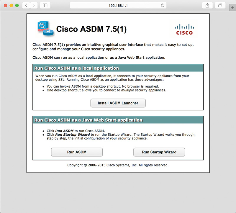
The Cisco ASA presents its self-signed certificate to the workstation so that a secure connection can be established. If the certificate is accepted, the Cisco ASA prompts you to present authentication credentials. If the ASDM authentication or enable password is not set up, there is no default username or password. If the enable password is defined, there is no default username, and you must use the enable password as the login password. If user authentication is enabled on the Cisco ASA through use of the aaa authentication http console command, then those login credentials must be provided. After a successful user authentication, the appliance presents two ways to launch ASDM:
![]() Run Cisco ASDM as a local application: The Cisco ASA offers a setup utility called asdm-launcher.msi, which can be saved to the workstation’s local hard drive.
Run Cisco ASDM as a local application: The Cisco ASA offers a setup utility called asdm-launcher.msi, which can be saved to the workstation’s local hard drive.
![]() Run Cisco ASDM as a Java Web Start application: The Cisco ASA launches ASDM in the client’s browser as a Java applet. This option is not feasible if a firewall that filters out Java applets exists between the client and the Cisco ASA.
Run Cisco ASDM as a Java Web Start application: The Cisco ASA launches ASDM in the client’s browser as a Java applet. This option is not feasible if a firewall that filters out Java applets exists between the client and the Cisco ASA.
Running the ASDM as a local application is currently supported on Windows-based and OS X–based operating systems.
When the ASDM application is launched, it prompts for the IP address of the Cisco ASA to which you are trying to connect, as well as the user authentication credentials.
Note
When you first launch the ASDM, the Cisco Smart Call Home functionality may prompt you to enable error and health information reporting either anonymously or by registering the product. You can choose not to enable if you are not interested.
If the user authentication is successful, the ASDM checks the current version of the installer application and downloads a new copy, if necessary. It loads the current configuration from the Cisco ASA and displays it in the GUI, as shown in Figure 3-5.

After you have established connectivity to the Cisco ASA, by using either the CLI or the ASDM, you are ready to start configuring the device. The following section guides you through basic setup of the Cisco ASA.
Setting Up a Device Name and Passwords
The default device name (also known as the hostname) of a Cisco ASA is ciscoasa. It is highly recommended that you set a unique device name to identify the Cisco ASA on the network. In addition, networking devices usually belong to a network domain. A domain name appends the unqualified hostnames with the configured domain name. For example, if the Cisco ASA tries to reach the host secweb by its hostname and the configured domain name on the Cisco ASA is securemeinc.org, the fully qualified domain name (FQDN) of the host is secweb.securemeinc.org.
In a new Cisco ASA, you can configure the Telnet and enable passwords. The Telnet password is used to authenticate remote sessions by using either the Telnet protocol or SSH. Prior to Cisco ASA software version 9.0(2), the default Telnet password was cisco. In version 9.0(2) and later, you must define a Telnet password using the password command. In addition, for an SSH connection, there is no default username or password in version 8.4(2) and later. You must configure the aaa authentication ssh console command to enable AAA authentication.
Example 3-6 shows the configuration you use in the CLI. The hostname is changed using the hostname command, the domain name is changed using the domain-name command, and the Telnet and enable passwords are changed using the password and enable password commands, respectively.
Example 3-6 Setting Up the Hostname, Domain Name, and Passwords
ciscoasa# configure terminal
ciscoasa(config)# hostname NY-1
NY-1(config)# domain-name securemeinc.org
NY-1 (config)# password C1$c0123
NY-1 (config)# enable password C1$c0123
Tip
If you view the configuration after adding the passwords, the Cisco ASA displays the encrypted passwords as follows:
NY-1# show running-config | include pass
enable password 9jNfZuG3TC5tCVH0 encrypted
passwd 2KFQnbNIdI.2KYOU encrypted
Configuring an Interface
Cisco ASA appliances come with a number of Fast Ethernet, Gigabit Ethernet, and 10-Gigabit Ethernet interfaces, depending on the platform. They also include one management interface (Management 0/0) in all one-rack unit (1 RU) models and two management interfaces (Management 0/0 and Management 0/1) in ASA 5580s and ASA 5585s. In addition, you can create one or more subinterfaces in each physical interface. The Fast Ethernet, Gigabit Ethernet, and 10-Gigabit Ethernet interfaces are used to route traffic from one interface to another, based on the configured policies, whereas the management interface is designed to establish out-of-band connections.
The Cisco ASA protects the internal network from external threats. Each interface is assigned a name to designate its role on the network. The most secure network is typically labeled as the inside network, whereas the least secure network is designated as the outside network. For semi-trusted networks, you can define them as demilitarized zones (DMZs) or any logical interface name. You must use the interface name to set up the configuration features that are linked to an interface.
The Cisco ASA also uses the concept of assigning security levels to the interfaces. The higher the security level, the more protected the interface. Consequently, the security level is used to reflect the level of trust of this interface with respect to the level of trust of another interface on the Cisco ASA. The security level can be between 0 and 100. Therefore, the most trusted network is placed behind the interface with a security level of 100, whereas the least protected network is placed behind an interface with a security level of 0. A DMZ interface should be assigned a security level between 0 and 100.
When an interface is configured with a nameif command, the Cisco ASA automatically assigns a preconfigured security level. If an interface is configured with the name inside, the Cisco ASA assigns a security level of 100. For all the other interface names, the Cisco ASA assigns a security level of 0.
Cisco ASA enables you to assign the same security level to more than one interface. If communication is required between the hosts on interfaces at the same security level, use the same-security-traffic permit inter-interface global configuration command. In addition, if an interface is not assigned a security level, it does not respond at the network layer.
By default, you do not need to define an access control list (ACL) to permit traffic from a high security–level interface to a low security–level interface; however, if you want to restrict traffic flows from a high security–level interface destined to a low security–level interface, you can define an ACL. If you configure an ACL for traffic originating from a high security–level interface to a low security–level interface, it disables the implicit permit from that interface. All traffic is now subject to the entries defined in that ACL.
An ACL must explicitly permit traffic traversing the security appliance from a lower to a higher security–level interface of the firewall. The ACL must be applied to the lower security–level interface or globally.
The most important parameter under the interface configuration is the assignment of an IP address. This is required if an interface is to be used to pass traffic in a Layer 3 firewall, also known as routed mode. An address can be either statically or dynamically assigned. For a static IP address, you configure an IP address and its respective subnet mask.
The Cisco ASA also supports interface address assignment through a Dynamic Host Configuration Protocol (DHCP) server and by using PPPoE. Assigning an address by using DHCP is a preferred method if an ISP dynamically allocates an IP address to the outside interface. You can also inform the Cisco ASA to use the DHCP server’s specified default gateway as the default route if the Obtain Default Route Using DHCP option is enabled in the ASDM. You can do this in the CLI by issuing the ip address dhcp [setroute] interface subcommand.
Note
If a Cisco ASA is deployed in transparent mode, the IP address is assigned in global configuration mode or on a bridge virtual interface (BVI) interface, depending of the version of code.
Assigning an interface address through DHCP is not supported if used with failover.
To configure a physical interface on a Cisco ASA by using ASDM, navigate to Configuration > Device Setup > Interfaces, select an interface, and click the Edit button.
Example 3-7 shows how to enable the GigabitEthernet0/0 interface as the outside interface and assigns a security level of 0. The IP address is 209.165.200.225 with a mask of 255.255.255.224.
Example 3-7 Enabling an Interface
NY-1# configure terminal
NY-1(config)# interface GigabitEthernet0/0
NY-1(config-if)# no shutdown
NY-1(config-if)# nameif outside
NY-1(config-if)# security-level 0
NY-1(config-if)# ip address 209.165.200.225 255.255.255.224
The ASDM enables you to configure the speed, duplex, and media type on an interface by opening the Edit Interface dialog box for the interface and clicking the Configure Hardware Properties button. By default, the speed and duplex are set to auto and can be changed to avoid link negotiations. If the speed and duplex settings do not match the speed and duplex settings on the other end of the Ethernet connection, you may see packet loss and experience performance degradation. The media type is either RJ-45 for copper-based interfaces or SFP for fiber-based interfaces. RJ-45 is the default media type.
Tip
The Ethernet-based interfaces on the Cisco ASA 5500 Series use the auto-MDI/MDIX (media-dependent interface/media-dependent interface crossover) feature, which does not require a crossover cable when connecting interfaces of two similar types. These interfaces perform an internal crossover when a straight network cable connects two similar interfaces. This feature works only when both the speed and duplex parameters are set to auto-negotiate.
Example 3-8 shows the outside interface set up with a connection speed of 1000 Mbps, using full-duplex mode.
Example 3-8 Configuring Speed and Duplex on an Interface
NY-1# configure terminal
NY-1(config)# interface GigabitEthernet0/0
NY-1(config-if)# speed 1000
NY-1(config-if)# duplex full
The Cisco ASA shows the output of interface-related statistics when you issue the show interface command from the CLI. Example 3-9 shows GigabitEthernet0/0 set up as the outside interface and has an IP address of 209.165.200.225 and GigabitEthernet0/1 set up as the inside interface with an IP address of 192.168.10.1. This command also shows the packet rate and the total number of packets entering and leaving the interface.
Example 3-9 show interface Command Output
NY-1# show interface
Interface GigabitEthernet0/0 "outside", is up, line protocol is up
Hardware is i82574L rev00, BW 1000 Mbps, DLY 10 usec
Full-duplex, 1000 Mbps
MAC address 000f.f775.4b53, MTU 1500
IP address 209.165.200.225, subnet mask 255.255.255.224
70068 packets input, 24068922 bytes, 0 no buffer
Received 61712 broadcasts, 0 runts, 0 giants
0 input errors, 0 CRC, 0 frame, 0 overrun, 0 ignored, 0 abort
0 L2 decode drops
13535 packets output, 7196865 bytes, 0 underruns
0 output errors, 0 collisions, 0 interface resets
0 babbles, 0 late collisions, 0 deferred
0 lost carrier, 0 no carrier
input queue (curr/max packets): hardware (0/1) software (0/11)
output queue (curr/max packets): hardware (0/19) software (0/1)
Traffic Statistics for "outside":
70081 packets input, 23044675 bytes
13540 packets output, 6992176 bytes
49550 packets dropped
1 minute input rate 1 pkts/sec, 362 bytes/sec
1 minute output rate 1 pkts/sec, 362 bytes/sec
1 minute drop rate, 0 pkts/sec
5 minute input rate 1 pkts/sec, 342 bytes/sec
5 minute output rate 1 pkts/sec, 362 bytes/sec
5 minute drop rate, 0 pkts/sec
Interface GigabitEthernet0/1 "inside", is up, line protocol is up
Hardware is i82546GB rev03, BW 1000 Mbps, DLY 10 usec
Auto-Duplex(Full-duplex), Auto-Speed(1000 Mbps)
MAC address 000f.f775.4b55, MTU 1500
IP address 192.168.10.1, subnet mask 255.255.255.0
1447094 packets input, 152644956 bytes, 0 no buffer
Received 1203884 broadcasts, 0 runts, 0 giants
0 input errors, 0 CRC, 0 frame, 0 overrun, 0 ignored, 0 abort
20425 L2 decode drops
332526 packets output, 151244141 bytes, 0 underruns
0 output errors, 0 collisions, 0 interface resets
0 babbles, 0 late collisions, 0 deferred
0 lost carrier, 0 no carrier
input queue (curr/max packets): hardware (0/1) software (0/14)
output queue (curr/max packets): hardware (0/26) software (0/1)
Traffic Statistics for "inside":
777980 packets input, 80481496 bytes
151736 packets output, 85309705 bytes
395607 packets dropped
1 minute input rate 0 pkts/sec, 58 bytes/sec
1 minute output rate 0 pkts/sec, 0 bytes/sec
1 minute drop rate, 0 pkts/sec
5 minute input rate 0 pkts/sec, 66 bytes/sec
5 minute output rate 0 pkts/sec, 0 bytes/sec
5 minute drop rate, 0 pkts/sec
Configuring the Cisco ASA to Redirect Traffic to the Cisco ASA FirePOWER Module
As you learned in Chapter 2, you can configure the Cisco ASA FirePOWER module in inline mode or in monitor-only mode. Follow these steps to configure the Cisco ASA to redirect traffic to the Cisco ASA FirePOWER module in inline mode or monitor-only mode:
Step 1. Log in to the ASDM.
Step 2. Navigate to Configuration > Firewall > Service Policy Rules.
Note
If you previously had a legacy IPS module or CX module configured and an active service policy in the Cisco ASA, you must remove that policy before you configure the Cisco ASA FirePOWER Services policy. If your Cisco ASA is running in multiple context mode, you must configure the service policy within each security context.
Step 3. Click the Add button to add a new service policy rule. The screen shown in Figure 3-6 appears.

Step 4. Specify whether the policy will apply to a particular interface or globally and click Next. In this example, the policy will apply globally.
Step 5. After you click Next, the screen shown in Figure 3-7 appears.

Step 6. Enter the name of the new traffic class (for example, firePOWER-class).
Step 7. Enter an optional description.
Step 8. Optionally specify criteria for the traffic that will be matched and sent to the Cisco ASA FirePOWER module or use the default class (class-default). In this example, the class will match all traffic because the Any traffic checkbox is checked under the Traffic Match Criteria field.
Step 9. Click Next. The Rule Actions page shown in Figure 3-8 appears.
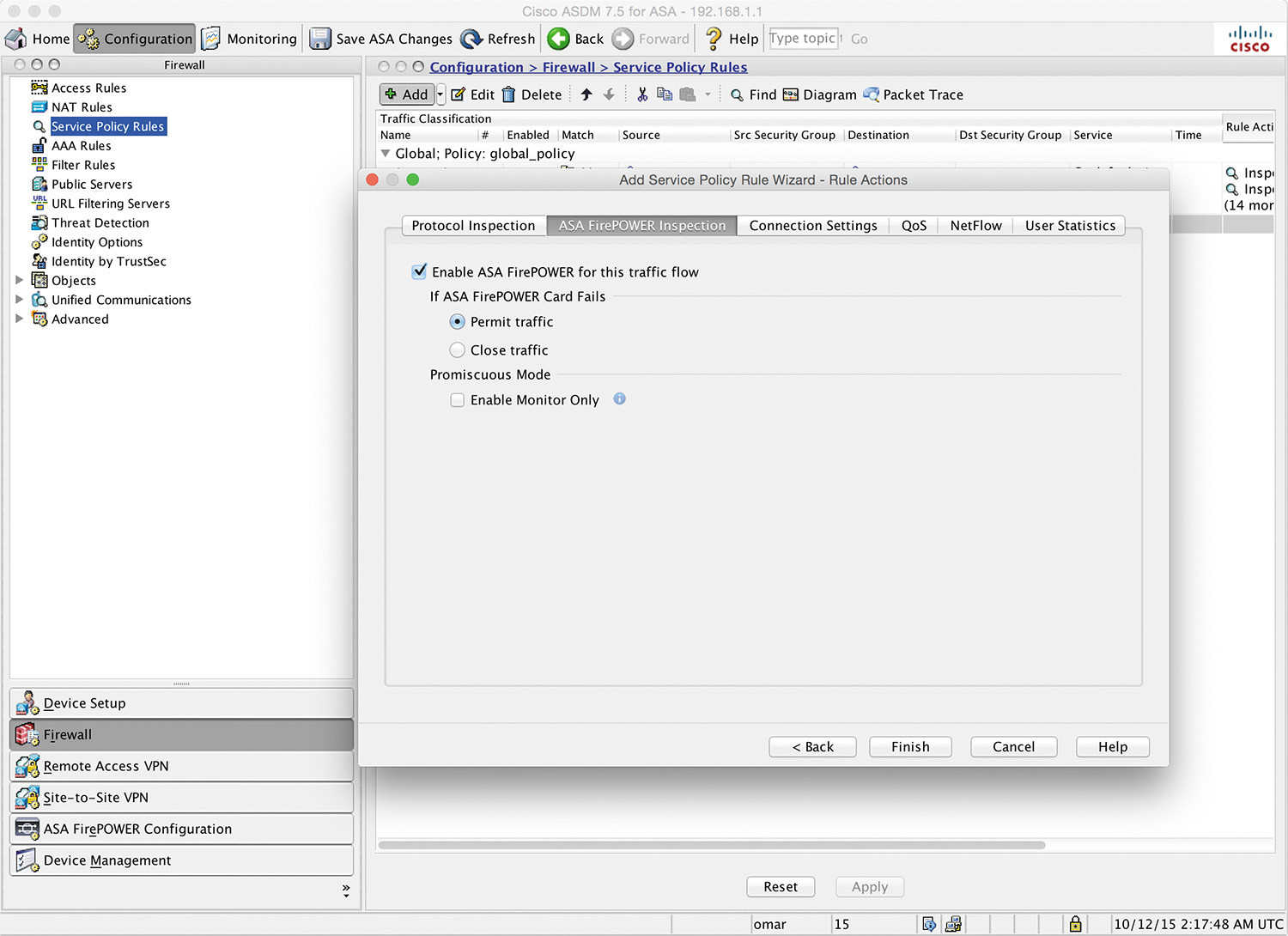
Step 10. Navigate to the ASA Firepower Inspection tab and check the Enable ASA Firepower for this traffic flow checkbox, as shown in Figure 3-8.
Step 11. Optionally configure the Cisco ASA to pass traffic if the Cisco ASA FirePOWER module fails (this is referred to as “fail open”) or configure the Cisco ASA to stop all traffic (or “fail close”). In Figure 3-8, the Cisco ASA is configured to fail open because the Permit traffic option is selected in the If ASA Firepower Card Fails area.
Step 12. Optionally check Enable Monitor Only to send a read-only copy of traffic to the module. This is also referred to as “inline tap mode.” (By default, the Cisco ASA sends all traffic to the Cisco ASA FirePOWER module in inline mode.) In Figure 3-8, the Cisco ASA is configured to send all traffic to the Cisco ASA FirePOWER module, and the module is configure in inline mode.
Step 13. Click Finish. The new service policy is shown on the Service Policy Rules page in ASDM, as shown in Figure 3-9.

Example 3-10 shows the command-line interface (CLI) commands that were applied on the Cisco ASA by ASDM.
Example 3-10 Configuring the Service Policy Using the CLI
! The class map
class-map firePOWER-class
description class to send all traffic to the Firepower module
! Matching all traffic to be sent to the Firepower module
match any
!
! Applying the class to the policy map
policy-map global_policy
class firePOWER-class
! The Firepower module configured to fail open
sfr fail-open
!
! Applying the policy map to the service policy
service-policy global_policy global
Configuring the Cisco ASA FirePOWER Module for the FMC
You can register the Cisco ASA FirePOWER module to the Firepower Management Center (FMC). Chapter 12, “Reporting and Troubleshooting with Cisco Next-Generation IPS,” covers the FMC in detail. Complete the following steps to register the Cisco ASA FirePOWER module to the FMC:
Step 1. Log in to the Cisco ASA FirePOWER module.
Step 2. Use the configure manager command as shown in the following example:
configure manager add 192.168.1.89 thisISaRegKey
In this example, the IP address of the FMC is 192.168.1.89. You can also use the DNS hostname or an IPv6 address (if IPv6 is enabled in your network). If the FMC is not directly addressable, use the DONTRESOLVE keyword. In this example, the registration key is thisISaRegKey. The registration key is a unique alphanumeric registration key required to register a Cisco ASA FirePOWER module to the FMC. You can also enter an optional alphanumeric string (nat_id) that is used during the registration process between the FMC and the ASA FirePOWER module. This is required if the DONTRESOLVE keyword is used. In deployments where Network Address Translation (NAT) is configured, you must provide a hostname or an IP address either when you are configuring remote management or when you are adding the managed appliance. A self-generated alphanumeric registration key up to 37 characters in length identifies the connection. You can configure an optional unique alphanumeric NAT ID (nat_id) that can help the FMC establish communications in a NAT environment. The NAT ID must be unique among all NAT IDs used to register managed appliances.
Step 3. Type exit to exit the configuration mode.
Configuring the Cisco ASA FirePOWER Module Using the ASDM
You can use the ASDM to configure the Cisco ASA FirePOWER module in only certain platforms, including the Cisco ASA 5506-X, 5506H-X, 5506W-X, 5508-X, and 5516-X appliances.
Note
For additional compatibility information, visit www.cisco.com/c/en/us/td/docs/security/asa/compatibility/asamatrx.html#48552.
The following sections covers how to configure the Cisco ASA FirePOWER module using the ASDM in supported platforms.
Configuring Access Control Policies
To view the access control policies that are applied in the Cisco ASA FirePOWER module, navigate to Configuration > ASA FirePOWER Configuration > Policies > Access Control Policy, as shown in Figure 3-10.

Creating a New Access Control Policy
Follow these steps to create a new access control policy in the Cisco ASA FirePOWER module:
Step 1. Click the New Policy button. The dialog shown in Figure 3-11 appears.

Step 2. Enter a name for the new access policy. In this example, the name of the new policy is myPolicy.
Step 3. Enter an optional description for the policy.
Step 4. Set Default Action to either Block all traffic or Intrusion Prevention. If you select the default action to Block all traffic, all traffic will be blocked without further inspection. In this example, the default action is set to Intrusion Prevention. When you first create an access control policy, you cannot choose to trust traffic as the default action. If you want to trust all traffic by default, change the default action after you create the policy. You can also use and modify the initial system-provided policy named Default Trust All Traffic. Figure 3-12 shows the Default Action dropdown menu options.

You can also copy an existing policy from this ASA FirePOWER module or import a policy from another ASA FirePOWER module.
As previously mentioned, in this example, Intrusion Prevention is set as the default action. Therefore, the Cisco ASA FirePOWER module creates a policy with the Intrusion Prevention: Balanced Security and Connectivity default action.
Step 5. Click Store ASA Firepower Changes.
Adding Rules to the Access Control Policy
You can more granularly control network traffic by adding rules to an access control policy. The rules within an access control policy are organized using a numbering scheme starting at 1. The Firepower system matches traffic to access control rules by ascending rule number. Typically, the Firepower system process network traffic according to the first access control rule, where all the rule’s conditions match the traffic. These conditions include the following:
![]() Security zone
Security zone
![]() Network or geographical location
Network or geographical location
![]() Applications
Applications
![]() Requested URLs
Requested URLs
![]() Users
Users
To add a rule, click the Add Rule button, and the screen shown in Figure 3-13 appears.

Each rule also has an action that determines whether you monitor, trust, block, or allow matching traffic. When you allow traffic, you can specify that the system first inspect it with intrusion or file policies to block any exploits, malware, or prohibited files before they reach your assets or exit your network. On the other hand, after the system trusts or blocks traffic, it does not perform further inspection. Figure 3-14 shows the Action dropdown menu options.

To configure rules based on security zones, navigate to the Zones tab. You can also configure rule conditions to match network or geographical locations. Figure 3-15 shows how to configure a rule condition based on geographical location of the source and destination networks. For instance, you can block or allow traffic that is sourced or destined to a given geographical location. In Figure 3-15, the source networks are based in North America (geolocation), and the destination networks are in Asia.

Cisco Security Intelligence–based traffic filtering and some decoding and preprocessing occur before network traffic is evaluated by access control rules. The system matches traffic to access control rules in the order you specify. In most cases, the system handles network traffic according to the first access control rule where all the rule’s conditions match the traffic. Some of the filtering capabilities may rely on Layer 7 (application) information, where the actual flow of the application may not be determined until a few packets are analyzed in the communication between two or more hosts. Conditions can be simple or complex; you can control traffic by security zone, network or geographical location, port, application, requested URL, and user.
You can also create rules based on the type and the risk of the application. Figure 3-16 shows how to create a rule based on application conditions, on the Applications tab.

Figure 3-17 shows how to use the Ports tab to create a rule based on given application ports. You can select predefined ports/applications such as FTP, Bittorrent, DNS over TCP or UDP, and so on.

You can also create rules that match known URLs to sites known to be hosting pornography, drug content, dating sites, and many other categories. The URL filtering license is required in order to configure and enable rules based on URLs. Figure 3-18 shows how to use the URLs tab to configure a rule based on URL categories.

Security Intelligence
Security Intelligence from Cisco is available as a first line of defense against malicious Internet sites and known malicious IP addresses. You can configure this feature to instantly blacklist (block) connections based on the latest reputation intelligence from Cisco Talos. You can configure access control policies with whitelists and blacklists, based on Cisco Talos Security Intelligence by navigating to the Security Intelligence tab under a given access policy, as shown in Figure 3-19.

You can override blacklists with custom whitelists in order to ensure continual access to critical resources. This traffic filtering takes place before any other policy-based inspection, analysis, or traffic handling, including rules and the default action.
HTTP Responses
You can customize a web page for blocked URLs. When the system blocks a given HTTP web request, you can customize what the user sees in a web browser depending on how the session is blocked. For example, you can select Block or Block with reset to deny the connection. A blocked session times out; the system resets Block with reset connections. On the other hand, for both blocking actions, you can override the default browser or server page with a custom page that explains that the connection was denied. The Cisco ASA Firepower system calls this custom page an HTTP response page.
You can edit the block response page by navigating to the HTTP Responses tab under the access control policy, as shown in Figure 3-20.

If you set the Cisco ASA FirePOWER module action to Interactive Block or Interactive Block with reset, you can configure an interactive HTTP response page that warns users but also allows them to click a button to continue or refresh the page to load the originally requested site. Users may have to refresh after bypassing the response page to load page elements that did not load. You can either display a generic system-provided response page or enter custom HTML, as shown in Figure 3-21.

Access Control Policy Advanced Settings
The advanced access control policy settings typically require little or no modification because the default settings are appropriate for most deployments. However, you can also customize the following advanced settings (see Figure 3-22):
![]() General Settings: You can customize the number of characters you store in the Cisco ASA FirePOWER module database for each URL requested by users.
General Settings: You can customize the number of characters you store in the Cisco ASA FirePOWER module database for each URL requested by users.
![]() Network Analysis and Intrusion Policies: You can change the access control policy’s default intrusion policy and associated variable set, which are used to initially inspect traffic before the system can determine exactly how to inspect that traffic. You can also change the access control policy’s default network analysis policy, which administers many preprocessing options. In addition, you can use custom network analysis rules and network analysis policies to tailor preprocessing options to specific security zones and networks.
Network Analysis and Intrusion Policies: You can change the access control policy’s default intrusion policy and associated variable set, which are used to initially inspect traffic before the system can determine exactly how to inspect that traffic. You can also change the access control policy’s default network analysis policy, which administers many preprocessing options. In addition, you can use custom network analysis rules and network analysis policies to tailor preprocessing options to specific security zones and networks.
![]() File and Malware Settings: You can set performance options for file control, file storage, and advanced malware protection.
File and Malware Settings: You can set performance options for file control, file storage, and advanced malware protection.
![]() Transport/Network Layer Preprocessor Settings: You can create preprocessor settings that are applied globally to all networks, zones, and VLANs where you apply your access control policy.
Transport/Network Layer Preprocessor Settings: You can create preprocessor settings that are applied globally to all networks, zones, and VLANs where you apply your access control policy.
![]() Detection Enhancement Settings: You can use adaptive profiles to improve reassembly of packet fragments and TCP streams in passive deployments, based on your network’s host operating systems.
Detection Enhancement Settings: You can use adaptive profiles to improve reassembly of packet fragments and TCP streams in passive deployments, based on your network’s host operating systems.
![]() Performance Settings and Latency-Based Performance Settings: You can tune and improve the performance of your system as it analyzes traffic for attempted intrusions.
Performance Settings and Latency-Based Performance Settings: You can tune and improve the performance of your system as it analyzes traffic for attempted intrusions.

Configuring Intrusion Policies
You can configure intrusion policies by navigating to Configuration > ASA FirePOWER Configuration > Policies > Intrusion Policy, where you can view your current custom intrusion policies, edit them, or create new ones. To create a new intrusion policy, click Create Policy to display the screen shown in Figure 3-23.

You must provide a name for the new intrusion policy, specify a base policy, and specify drop behavior.
The Drop when Inline setting defines how the Firepower module handles drop rules (intrusion or preprocessor rules whose rule state is set to Drop and Generate Events) and other intrusion policy configurations that affect traffic. You should enable drop behavior in inline deployments when you want to drop or replace malicious packets.
Note
In Cisco ASA FirePOWER modules that are configured in passive mode, the system cannot affect traffic flow, regardless of the drop behavior.
The base policy sets the intrusion policy’s default settings. You can use either a system-provided or custom policy as your base policy. Figure 3-23 shows the Base Policy dropdown menu options.
You can edit an intrusion policy by navigating to Configuration > ASA FirePOWER Configuration > Policies > Intrusion Policy and clicking the pencil (edit) button; the screen shown in Figure 3-24 appears.

To customize how rules are displayed in the intrusion policy or sort rules by several criteria, click Manage Rules to display the screen shown in Figure 3-25.

In the page shown in Figure 3-25, you can also display the details for a specific rule to see rule settings, rule documentation, and other rule settings. This page has four key categories:
![]() Filtering features
Filtering features
![]() Rule attribute menus
Rule attribute menus
![]() Rules listing
Rules listing
![]() Rule details
Rule details
Note
The column headers relate to the menus in the menu bar, where you access those configuration items.
Custom Rules
You can create custom rules or edit or clone existing ones by navigating to Configuration > ASA FirePOWER Configuration > Policies > Intrusion Policy > Rule Editor (see Figure 3-26).

To modify an existing rule, click the pencil icon next to the specific rule. You can also import rules from another system by clicking the Import Rules button to display the screen shown in Figure 3-27.

New vulnerabilities are reported daily by many vendors in the industry. Cisco Talos releases rule updates that you can first import onto your Cisco ASA Firepower module and then implement by applying affected access control, network analysis, and intrusion policies.
Tip
Rule updates are cumulative, and Cisco recommends that you always import the latest update. You cannot import a rule update that either matches or predates the version of the currently installed rules. Rule updates may contain new binaries, so make sure your process for downloading and installing them complies with your security policies. In addition, rule updates may be large, so import rules during periods of low network use.
If you are an advanced user, you can create a new rule by clicking Create Rule in the main rule editor page (refer to Figure 3-26). The screen shown in Figure 3-28 appears.

When creating a custom standard text rule, you set the rule header settings and the rule keywords and arguments. After you create a custom rule, you can search for it by using the rule number. The format of the rule number is as follows:
GID:SID:Rev
The rule number for all standard text rules starts with 1. The second part of the rule number, the Snort ID (SID), indicates whether the rule is a local rule or a rule provided by Cisco. Snort IDs for custom rules start at 1,000,000, and the SID for each new local rule is incremented by 1. The last part of the rule number is the revision number. Each time you edit a custom rule, the revision number increments by 1.
You enter the message you want displayed with the event in the Message field. The Classification dropdown menu allows you to select a classification to describe the type of event. Figure 3-29 shows examples of the options available in the Classification dropdown menu.

The Action list allows you to define the type of rule you are creating (alert to create an alert or pass to create a rule that ignores traffic that triggers the rule). You can select from the Protocol dropdown menu the traffic protocol (tcp, udp, icmp, or ip) of packets you want the rule to inspect.
The Direction dropdown menu allows you to select the operator that indicates which direction of traffic you want to trigger the rule.
You can also define the source and destination IP addresses and ports that should trigger the rule. Select Directional under the Direction dropdown menu to match traffic that moves from the source IP address to the destination IP address. Select Bidirectional to match traffic that moves in either direction.
You can select the detection options under the Detection Options dropdown menu and click the Add Option button. Figure 3-30 shows examples of the different detection options available.

Configuring File Policies
You can configure file policies in a Cisco ASA FirePOWER module to perform advanced malware protection and file control. You can configure file policies by navigating to Configuration > ASA FirePOWER Configuration > Policies > Files. To create a new file policy, click the New File Policy button to open the dialog shown in Figure 3-31.

Enter the name of the new file policy and a description and then click the Store ASA FirePOWER Changes button. The screen shown in Figure 3-32 appears.

The policy has two access control rules, both of which use the Allow action and are associated with file policies. The policy’s default action is also to allow traffic, but without file policy inspection. A file policy, like its parent access control policy, contains rules that determine how the system handles files that match the conditions of each rule. You can configure file rules to take different actions for different file types, application protocols, or directions of transfer. To add a new file rule, click the Add File Rule button. The Add File Rule screen shown in Figure 3-33 appears.

Note
Each file rule has an associated action that determines how the system handles traffic that matches the conditions of the rule.
You can set separate rules within a file policy to take different actions for different file types, application protocols, or directions of transfer.
The rule actions can be configured to the following:
![]() Detect Files: To log the detection of specific file types while still allowing their transmission
Detect Files: To log the detection of specific file types while still allowing their transmission
![]() Block Files: To block specific file types
Block Files: To block specific file types
![]() Malware Cloud Lookup: To log the malware disposition of files traversing the network based on a cloud lookup, while still allowing their transmission
Malware Cloud Lookup: To log the malware disposition of files traversing the network based on a cloud lookup, while still allowing their transmission
![]() Block Malware: To calculate the SHA-256 hash value of specific file types, use a cloud lookup process to first determine whether files traversing the network contain malware, and block files that represent threats
Block Malware: To calculate the SHA-256 hash value of specific file types, use a cloud lookup process to first determine whether files traversing the network contain malware, and block files that represent threats
You can select different file type categories in the File Type Categories section and select or search for specific file types under the File Types section (refer to Figure 3-33). Click the Add button to add file categories and file types.
Reusable Object Management
The Cisco ASA FirePOWER module allows you to create named objects, which are reusable configurations that associate a name with a value so that a named object is used instead. You can configure the following object types:
![]() Network-based objects that represent IP addresses and networks, port/protocol pairs, security zones, and origin/destination country (geographical location)
Network-based objects that represent IP addresses and networks, port/protocol pairs, security zones, and origin/destination country (geographical location)
![]() Security Intelligence feeds and lists
Security Intelligence feeds and lists
![]() Application filters
Application filters
![]() Ports
Ports
![]() URLs
URLs
![]() File lists
File lists
![]() Intrusion policy variable sets
Intrusion policy variable sets
You can use these objects in various places in the ASA FirePOWER module, including access control policies, network analysis policies, intrusion policies and rules, reports, dashboards, and so on. You can configure these objects by navigating to Configuration > ASA FirePOWER Configuration > Object Management.
Keeping the Cisco FirePOWER Module Up-to-Date
Cisco provides different types of updates for the Cisco ASA FirePOWER module, including the following:
![]() Major and minor updates to the module software itself (patches, feature updates, and major updates)
Major and minor updates to the module software itself (patches, feature updates, and major updates)
![]() Rule updates
Rule updates
![]() Geolocation database (GeoDB) updates
Geolocation database (GeoDB) updates
![]() Vulnerability database (VDB) updates
Vulnerability database (VDB) updates
Patches include a limited range of fixes and usually change the fourth digit in the version number (for example, 5.4.2.1). Feature updates are more comprehensive than patches and generally include new features and usually change the third digit in the version number (for example, 5.4.3). Major updates include new features and functionality and may involve large-scale changes and usually change the first or second digit in the version number (for example, 5.4 or 5.5).
To apply and upload product updates, go to Configuration > ASA FirePOWER Configuration > Updates, navigate to the Product Updates tab, and click Upload Update, as shown in Figure 3-34.

VDB updates affect the database of known vulnerabilities to which hosts may be susceptible. Intrusion rule updates provide new and updated intrusion rules and preprocessor rules, modified states for existing rules, and modified default intrusion policy settings.
Tip
Rule updates may also delete rules, provide new rule categories and default variables, and modify default variable values.
To configure or upload rule updates, go to Configuration > ASA FirePOWER Configuration > Updates and navigate to the Rule Updates tab, as shown in Figure 3-35.

Cisco recommends that you always import the latest update. You can apply one-time rule updates or set the interval of recurring rule update imports.
Rule updates are cumulative. You cannot import a rule update that either matches or predates the version of the currently installed rules.
Geolocation updates provide updated information on physical locations with detected routable IP addresses. As you learned earlier in this chapter, you can use geolocation data as a condition in access control rules. To configure or upload geolocation updates, go to Configuration > ASA FirePOWER Configuration > Updates and navigate to the Geolocation Updates tab, as shown in Figure 3-36.

You can import a one-time geolocation update or configure recurring updates, as shown in Figure 3-36.
Firepower Threat Defense
As you learned in previous chapters, the Cisco Firepower Threat Defense (FTD) software can run on the following Cisco ASA models:
![]() Cisco ASA 5506-X
Cisco ASA 5506-X
![]() Cisco ASA 5506H-X
Cisco ASA 5506H-X
![]() Cisco ASA 5506W-X
Cisco ASA 5506W-X
![]() Cisco ASA 5512-X
Cisco ASA 5512-X
![]() Cisco ASA 5515-X
Cisco ASA 5515-X
![]() Cisco ASA 5516-X
Cisco ASA 5516-X
![]() Cisco ASA 5525-X
Cisco ASA 5525-X
![]() Cisco ASA 5545-X
Cisco ASA 5545-X
![]() Cisco ASA 5555-X
Cisco ASA 5555-X
Cisco is always adding new models to its next-generation security appliances. You should visit the Cisco Firepower compatibility guide to obtain the most recent information: www.cisco.com/c/en/us/td/docs/security/firepower/compatibility/firepower-compatibility.html.
Installing FTD Boot Image and Software
FTD provides next-generation firewall services, including stateful firewalling, dynamic routing, next-generation intrusion prevention systems (NGIPS), Application Visibility and Control (AVC), URL filtering, and Advanced Malware Protection (AMP) in a unified system image. You can use an FTD device in single-context mode and in routed or transparent mode.
If you are deploying a Cisco ASA 5506-X, Cisco ASA 5508-X, or Cisco ASA 5516-X, you must run ROMMON version 1.1.8 or later. You can transfer the new ROMMON image by using the copy command, as mentioned previously in this chapter. Once you copy the ROMMON image, you can use the upgrade rommon disk0: rommon-image command to upgrade the ROMMON in the system. The Cisco ASA then updates the ROMMON and reboots the system.
To install the FTD software in a supported Cisco ASA, you use the same procedure you learned earlier: You first install the boot image in ROMMON by pressing Esc during the boot process, and then, at the ROMMON prompt, enter set and configure the following parameters to establish temporary connectivity to the TFTP server:
![]() ADDRESS: The management IP address of the Cisco ASA.
ADDRESS: The management IP address of the Cisco ASA.
![]() SERVER: The IP address of the TFTP server.
SERVER: The IP address of the TFTP server.
![]() GATEWAY: The gateway address to the TFTP server. If the TFTP server is directly attached to Management 1/0, use the IP address of the TFTP server. If the TFTP server and management address are on the same subnet, do not configure the gateway, or TFTP boot will fail.
GATEWAY: The gateway address to the TFTP server. If the TFTP server is directly attached to Management 1/0, use the IP address of the TFTP server. If the TFTP server and management address are on the same subnet, do not configure the gateway, or TFTP boot will fail.
![]() IMAGE: The boot image path and image name on the TFTP server. For example, if you place the file on the TFTP server in /tftpboot/images/filename, the IMAGE value is images/ftd-boot-version.cdisk or ftd-boot-version.lfbff.
IMAGE: The boot image path and image name on the TFTP server. For example, if you place the file on the TFTP server in /tftpboot/images/filename, the IMAGE value is images/ftd-boot-version.cdisk or ftd-boot-version.lfbff.
After you enter that information, use the sync command to save the settings and issue the tftpdnld command to initiate the download and boot process. The OS image should begin downloading through TFTP. When the OS download is complete, the system automatically boots with the image it just downloaded and stops at the boot CLI prompt.
After installing the boot image, use the setup command to enter the management IP address, subnet mask, and gateway and then use the system install [noconfirm] url command (as discussed earlier) to transfer and install the FTD software:
> system install http://10.10.10.123/ftd-6.0.1-123.pkg
After the FTD image is installed, choose Yes when the appliance reboot option is displayed. The Cisco ASA reboots, and the system prompts you for a username and password when the reboot is complete. At this point, the OS and package installation is complete.
FTD Firewall Mode
The FTD software supports routed and transparent firewall modes, just like the legacy Cisco ASA software. The default is routed. In transparent mode you can create up to 250 bridge groups, with 4 interfaces per bridge group. In devices configured in transparent mode, the diagnostic interface updates the MAC address table in the same manner as a data interface; therefore, you should not connect both a diagnostic interface and a data interface to the same switch unless you configure one of the switch ports as a routed port. Otherwise, if traffic arrives on the diagnostic interface from the physically connected switch, FTD updates the MAC address table to use the diagnostic interface, instead of the data interface, to access the switch. This action causes a temporary traffic interruption; the FTD device does not re-update the MAC address table for packets from the switch to the data interface for at least 30 seconds for security reasons.
To change the firewall mode in FTD, you can use the configure firewall [routed | transparent] command, as demonstrated here:
> configure firewall transparent
This will destroy the current interface configurations, are you sure that you want
to proceed? [y/N] y
The firewall mode was changed successfully.
FTD Interface Types
There are three general types of interfaces in FTD:
![]() Management interface
Management interface
![]() Diagnostic interface
Diagnostic interface
![]() Routed mode deployment
Routed mode deployment
The management interface is a dedicated interface for management tasks and registering the device to the FMC. It runs a separate SSH server and uses its own local authentication, IP address, and static routing. To configure its settings by using the CLI, you can use the configure network command or change the IP address in the FMC by navigating to Devices > Device Management > Devices > Management.
The diagnostic interface only allows management traffic and does not allow through traffic. You can configure the diagnostic logical interface along with the rest of the data interfaces in the FMC by navigating to Devices > Device Management > Interfaces. Using the diagnostic interface is optional. The diagnostic interface and data interfaces can be used to communicate with external LDAP or RADIUS servers for authentication.
Cisco recommends that you not configure the diagnostic interface and, in fact, suggests that you remove the name for this interface if you do not have an inside router. The major benefit of disabling the diagnostic interface is that you can place the management interface on the same network as any other data interfaces. If you leave the diagnostic interface configured, its IP address must be on the same network as the management IP address, and it counts as a regular interface that cannot be on the same network as any other data interfaces. Because the management interface requires Internet access for updates, putting the management interface on the same network as an inside interface means you can deploy the FTD device with only a switch on the inside and point to the inside interface as its gateway.
FTD Security Zones
Each interface must be assigned to a single security zone. This is the same principle you learned earlier, with Cisco ASA running Firepower Services. You apply security policy based on zones. For instance, you can configure your access control policy to enable traffic to go from inside to outside but not from outside to inside, for example. You can create security zones in the FMC by navigating to the Objects page.
You can also add a security zone can when you are configuring an interface. You can only add interfaces to the correct zone type for your interface—either Passive, Inline, Routed, or Transparent zone types.
Note
The diagnostic and management interfaces cannot belong to a security zone.
Static and Dynamic Routing in FTD
FTD supports static routes and the following dynamic routing protocols:
![]() OSPF
OSPF
![]() BGP
BGP
![]() RIP
RIP
To add a static route, follow these steps:
Step 1. Log in to the FMC, navigate to Devices > Device Management, and edit the FTD device. Then select the Routing tab.
Step 2. Select Static Route from the table of contents and click Add Routes.
Step 3. Select IPv4 or IPv6.
Step 4. Enter or select the Interface to which this static route applies. In the Available Network list, enter or select the destination network. If you are adding a default route, create an object with the address 0.0.0.0/0 and select it there.
Step 5. Enter or select the gateway router in the Gateway or IPv6 Gateway field.
Step 6. Enter the number of hops to the destination network in the Metric field. Valid values range from 1 to 255, and the default value is 1.
Step 7. If you want to monitor route availability, in the Route Tracking field enter or select the name of a service level agreement (SLA) Monitor object that defines the monitoring policy. This is only supported in IPv4 and not in IPv6.
Step 8. Click OK.
To configure OSPF, RIP, or BGP, navigate to Devices > Device Management and edit the FTD device and then select the routing protocol in the Routing area.
Note
OSPF, RIP, and BGP routing protocol configuration is very similar to the legacy Cisco ASA software configuration.
The access policy, IPS, AMP, URL filtering, and other configurations in FTD are the same as the Firepower software options you learned previously in this chapter.
Summary
In this chapter you have learned how to configure the Cisco ASA and the Cisco ASA FirePOWER module. You have seen step-by-step examples of how to set up the Cisco ASA FirePOWER module in Cisco ASA 5585-X and in Cisco ASA 5500-X appliances. You have also learned how to configure the Cisco ASA to redirect traffic to the Cisco ASA FirePOWER module. The Cisco ASA FirePOWER module can be managed and configured with the FMC. In addition, you have learned how to configure the Cisco ASA FirePOWER module for the FMC. The Cisco ASA FirePOWER module can be configured using ASDM in certain platforms only—the Cisco ASA 5506-X, 5506H-X, 5506W-X, 5508-X, and 5516-X appliances. In this chapter you have learned how to configure the Cisco ASA FirePOWER module using the ASDM in the supported platforms. You have learned how to configure access control, intrusion and file policies, and custom rules. In addition, you have learned how to configure reusable objects to ease configuration tasks. You have also learned how to apply product updates and how to import and schedule rule and geolocation database updates. Finally, you have gotten an overview of how to install the FTD software on a Cisco ASA as well as how to configure interfaces, security zones, and dynamic routing.