
Chapter 2. Introduction to and Design of Cisco ASA with FirePOWER Services
This chapter provides an introduction to the Cisco ASA with FirePOWER Services solution. It also provides design guidance and best practices for deploying Cisco ASA with FirePOWER Services. This chapter covers the following topics:
![]() Introduction to Cisco ASA FirePOWER Services
Introduction to Cisco ASA FirePOWER Services
![]() Inline versus promiscuous mode
Inline versus promiscuous mode
![]() Cisco ASA FirePOWER management options
Cisco ASA FirePOWER management options
![]() Cisco ASA FirePOWER Services sizing
Cisco ASA FirePOWER Services sizing
![]() Cisco ASA FirePOWER Services licensing
Cisco ASA FirePOWER Services licensing
![]() Compatibility with other Cisco ASA features
Compatibility with other Cisco ASA features
![]() Cisco ASA FirePOWER packet processing order of operations
Cisco ASA FirePOWER packet processing order of operations
![]() Cisco ASA FirePOWER Services and failover
Cisco ASA FirePOWER Services and failover
![]() Cisco ASA FirePOWER Services and clustering
Cisco ASA FirePOWER Services and clustering
![]() Deployment of the Cisco ASA FirePOWER Services in the Internet edge
Deployment of the Cisco ASA FirePOWER Services in the Internet edge
![]() Deployment of the Cisco ASA FirePOWER Services in VPN scenarios
Deployment of the Cisco ASA FirePOWER Services in VPN scenarios
![]() Deployment of the Cisco ASA FirePOWER Services in the data center
Deployment of the Cisco ASA FirePOWER Services in the data center
Introduction to Cisco ASA FirePOWER Services
In Chapter 1, “Fundamentals of Cisco Next-Generation Security,” you learned about the different Cisco next-generation security products and technologies. You also learned that those security technologies and processes should not focus solely on detection but should also provide the ability to mitigate the impact of an attack. Organizations must maintain visibility and control across the extended network during the full attack continuum:
![]() Before an attack takes place
Before an attack takes place
![]() During an active attack
During an active attack
![]() After an attacker starts to damage systems or steal information
After an attacker starts to damage systems or steal information
The Cisco ASA with FirePOWER Services and Cisco’s Advanced Malware Protection (AMP) provide a security solution that helps you discover threats and enforce and harden policies before an attack takes place. These technologies and solutions can help you detect, block, and defend against attacks that have already taken place. In Chapter 1 you also learned that the Cisco ASA family has members in many shapes and sizes, and you learned about their uses in small, medium, and large organizations.
Cisco introduced the Cisco ASA FirePOWER Services as part of the integration of the SourceFire technology. Cisco ASA FirePOWER Services provides the following key capabilities:
![]() Access control: This policy-based capability allows a network security administrator to define, inspect, and log the traffic that traverses a firewall. Access control policies determine how traffic is permitted or denied in a network. For instance, you can configure a default action to inspect all traffic or to block or trust all traffic without further inspection. You can also achieve a more complete access control policy with enrichment data based on security threat intelligence. Whether you configure simple or complex rules, you can control traffic based on security zones, network or geographical locations, ports, applications, requested URLs, and per user.
Access control: This policy-based capability allows a network security administrator to define, inspect, and log the traffic that traverses a firewall. Access control policies determine how traffic is permitted or denied in a network. For instance, you can configure a default action to inspect all traffic or to block or trust all traffic without further inspection. You can also achieve a more complete access control policy with enrichment data based on security threat intelligence. Whether you configure simple or complex rules, you can control traffic based on security zones, network or geographical locations, ports, applications, requested URLs, and per user.
![]() Intrusion detection and prevention: Intrusion detection and prevention help you detect attempts from an attacker to gain unauthorized access to a network or a host, create performance degradation, or steal information. You define intrusion detection and prevention policies based on your access control policies. You can create and tune custom policies at a very granular level to specify how traffic is inspected in a network.
Intrusion detection and prevention: Intrusion detection and prevention help you detect attempts from an attacker to gain unauthorized access to a network or a host, create performance degradation, or steal information. You define intrusion detection and prevention policies based on your access control policies. You can create and tune custom policies at a very granular level to specify how traffic is inspected in a network.
![]() AMP and file control: You can detect, track, capture, analyze, and optionally block the transmission of files, including malware files and nested files inside archive files in network traffic. File control also enables you to detect and block users from sending or receiving files of different specified types over a multitude of application protocols. You can configure file control as part of the overall access control policies and application inspection.
AMP and file control: You can detect, track, capture, analyze, and optionally block the transmission of files, including malware files and nested files inside archive files in network traffic. File control also enables you to detect and block users from sending or receiving files of different specified types over a multitude of application protocols. You can configure file control as part of the overall access control policies and application inspection.
![]() Application programming interfaces (APIs): Cisco ASA FirePOWER Services supports several ways to interact with the system using APIs.
Application programming interfaces (APIs): Cisco ASA FirePOWER Services supports several ways to interact with the system using APIs.
The Cisco ASA FirePOWER module can be a hardware module on the ASA 5585-X only or a software module that runs in a solid state drive (SSD) in all other Cisco ASA 5500-X models.
Note
The Cisco ASA FirePOWER Services module is not supported in the 5505. For the 5512-X through ASA 5555-X, you must install an SSD. The SSD is standard on the 5506-X, 5508-X, and 5516-X.
Inline versus Promiscuous Mode
The Cisco ASA FirePOWER module can be configured in either of the following modes:
![]() Inline mode
Inline mode
![]() Promiscuous monitor-only (passive) mode
Promiscuous monitor-only (passive) mode
Inline Mode
When the Cisco ASA FirePOWER module is configured in inline mode, the traffic passes through the firewall policies before it is sent to the Cisco ASA FirePOWER module.
Figure 2-1 illustrates the order of operations when the Cisco ASA FirePOWER module is configured in inline mode.
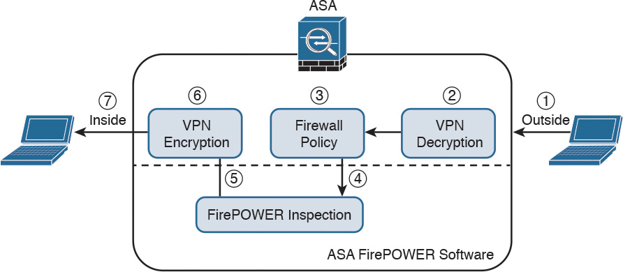
1. Network traffic is received on a given interface of the Cisco ASA. In this example, the traffic is received in the outside interface.
2. If IPsec or SSL VPN is configured, the incoming encrypted traffic is decrypted.
3. Firewall policies are applied to the traffic.
4. If the traffic is compliant and allowed by the firewall policies, it is sent to the Cisco ASA FirePOWER module.
5. The Cisco ASA FirePOWER module inspects the traffic and applies its security policies and takes appropriate actions. If traffic is not compliant with security policies or is determined to be malicious, the Cisco ASA FirePOWER module sends back a verdict to the ASA, and the ASA blocks the traffic and alerts the network security administrator. All valid traffic is allowed by the Cisco ASA.
6. If IPsec or SSL VPN is configured, the outgoing traffic is encrypted.
7. The network traffic is sent to the network.
Promiscuous Monitor-Only Mode
When the Cisco ASA FirePOWER module is configured in promiscuous monitor-only mode, a copy of each packet of the traffic that is defined in the service policy is sent to the Cisco ASA FirePOWER module.
Figure 2-2 illustrates the order of operations when the Cisco ASA FirePOWER module is configured in promiscuous monitor-only mode:
1. Network traffic is received on a given interface of the Cisco ASA. In this example, the traffic is received in the outside interface.
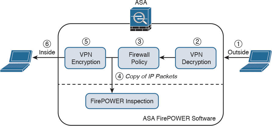
2. If IPsec or SSL VPN is configured, the incoming encrypted traffic is decrypted.
3. Firewall policies are applied to the traffic.
4. If the traffic is compliant and allowed by the firewall policies, a copy of each packet is sent to the Cisco ASA FirePOWER module. If traffic is not compliant with security policies or is determined to be malicious, the Cisco ASA FirePOWER module can be configured to alert the administrator, but it does not block the traffic.
5. If IPsec or SSL VPN is configured, the outgoing traffic is encrypted.
6. The network traffic is sent to the network.
As you can see, the most secure and effective way to configure the Cisco ASA FirePOWER module is in inline mode. You can configure the Cisco ASA FirePOWER module in promiscuous monitor-only mode when you are evaluating and performing capacity planning for a new deployment.
The Cisco ASA FirePOWER module modes are a bit different than those of the Cisco FirePOWER Series of appliances, which support the following deployment modes/options:
![]() Standalone IPS (active/standby)
Standalone IPS (active/standby)
![]() Clustering
Clustering
![]() SourceFire Redundancy Protocol (SFRP)
SourceFire Redundancy Protocol (SFRP)
![]() Bypass and non-bypass modules
Bypass and non-bypass modules
Cisco FirePOWER Series next-generation intrusion prevention systems (NGIPS) appliances can be deployed in multiple modes at once:
![]() Passive
Passive
![]() Inline
Inline
![]() Routed
Routed
![]() Switched
Switched
Note
Chapter 10, “Introduction to and Deployment of Cisco Next-Generation IPS,” covers the different modes of operations of the Cisco FirePOWER Series NGIPS appliances.
Cisco ASA FirePOWER Management Options
There are several options available for network security administrators to manage the Cisco ASA FirePOWER module. The Cisco ASA FirePOWER module provides a basic command-line interface (CLI) for initial configuration and troubleshooting only. Network security administrators can configure security policies on the Cisco ASA FirePOWER module using either of these methods:
![]() Administrators can configure the Cisco Firepower Management Center hosted on a separate appliance or deployed as a virtual machine (VM).
Administrators can configure the Cisco Firepower Management Center hosted on a separate appliance or deployed as a virtual machine (VM).
![]() Administrators can configure the Cisco ASA FirePOWER module deployed on Cisco ASA 5506-X, 5508-X, and 5516-X using Cisco’s Adaptive Security Device Manager (ASDM).
Administrators can configure the Cisco ASA FirePOWER module deployed on Cisco ASA 5506-X, 5508-X, and 5516-X using Cisco’s Adaptive Security Device Manager (ASDM).
Figure 2-3 shows a Cisco ASA with FirePOWER Services being managed by a Cisco Firepower Management Center (FMC) in a VM.
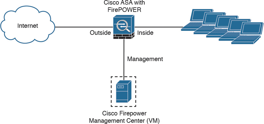
In Figure 2-3 the Cisco Firepower Management Center manages the Cisco ASA FirePOWER module via its management interface. The following section provides important information about configuring and accessing the Cisco ASA FirePOWER module management interface.
Accessing the Cisco ASA FirePOWER Module Management Interface in Cisco ASA 5585-X Appliances
In the Cisco ASA 5585-X, the Cisco ASA FirePOWER module includes a separate management interface. All management traffic to and from the Cisco ASA FirePOWER module must enter and exit this management interface, and the management interface cannot be used as a data interface.
The Cisco ASA FirePOWER module needs Internet access to perform several operations, such as automated system software updates and threat intelligence updates. If the module is managed by the Firepower Management Center, the FMC is the one that needs to have Internet access to perform those tasks.
Figure 2-4 shows an example of how you can physically connect the Cisco ASA FirePOWER module management interface to be able to reach the Internet via the Cisco ASA interface.
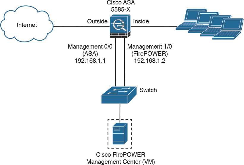
In Figure 2-4, the Cisco ASA 5585-X has two modules:
![]() A module running Cisco ASA software
A module running Cisco ASA software
![]() A module running FirePOWER Services
A module running FirePOWER Services
The Cisco ASA is managed via the interface named management 0/0 in this example. This interface is configured with the IP address 192.168.1.1. The Cisco ASA FirePOWER module is managed via the interface named management 1/0, configured with the IP address 192.168.1.2. The Cisco ASA FirePOWER module is being managed by a virtual Cisco Firepower Management Center. Both interfaces are connected to a Layer 2 switch in this example.
Note
You can use other cabling options with the Cisco ASA FirePOWER module management interface to be able to reach the Internet, depending on how you want to connect your network. However, the example illustrated in Figure 2-4 is one of the most common scenarios.
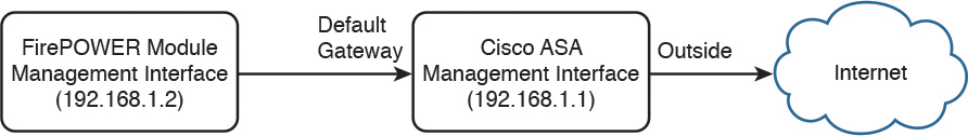
In order for the Cisco ASA FirePOWER module management interface to have an Internet connection, the default gateway of the Cisco ASA FirePOWER module is set to the Cisco ASA management interface IP address (192.168.1.1 in this example). Figure 2-5 illustrates the logical connection between the Cisco ASA FirePOWER module management interface and the Cisco ASA management interface.
Accessing the Cisco ASA FirePOWER Module Management Interface in Cisco ASA 5500-X Appliances
In the rest of the Cisco 5500-X appliances, the management interface is shared by the Cisco ASA FirePOWER module and the classic Cisco ASA software. These appliances include the Cisco ASA 5506-X, 5506W-X, 5506H-X, 5508-X, 5512-X, 5515-X, 5516-X, 5525-X, 5545-X, and 5555-X appliances.
Figure 2-6 shows a Cisco ASA 5516-X running Cisco ASA FirePOWER Services.
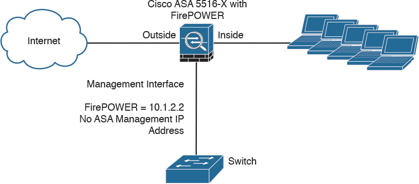
In Figure 2-6, the management interface is used by the Cisco ASA FirePOWER module. The management interface is configured with the IP address 10.1.2.2. You cannot configure an IP address for this interface in the Cisco ASA configuration. For the ASA 5506-X, 5508-X, and 5516-X, the default configuration enables the preceding network deployment; the only change you need to make is to set the module IP address to be on the same network as the ASA inside interface and to configure the module gateway IP address. For other models, you must remove the ASA-configured name and IP address for management 0/0 or 1/1 and then configure the other interfaces as shown in Figure 2-6.
Note
The management interface is considered completely separate from the Cisco ASA, and routing must be configured accordingly.
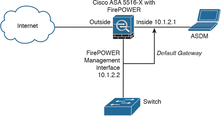
The Cisco ASA FirePOWER module default gateway is configured to be the inside interface of the Cisco ASA (10.1.2.1), as illustrated in Figure 2-7.
If you must configure the management interface separately from the inside interface, you can deploy a router or a Layer 3 switch between both interfaces, as shown in Figure 2-8. This option is less common, as you still need to manage the ASA via the inside interface.
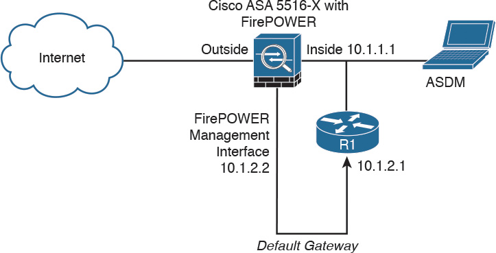
In Figure 2-8, the Cisco ASA FirePOWER module default gateway is the router labeled R1, with the IP address 10.1.2.1. The Cisco ASA’s inside interface is configured with the IP address 10.1.1.1. The Cisco ASA FirePOWER module must have a way to reach the inside interface of the ASA to allow for on-box ASDM management. On the other hand, if you are using FMC, the Cisco ASA FirePOWER module needs to have a way to reach the FMC.
Cisco ASA FirePOWER Services Sizing
It is really important that you understand the capabilities of each Cisco ASA model before you select the one that is appropriate for your specific deployment. Table 2-1 lists the maximum application visibility and control (AVC) and NGIPS throughput on each Cisco ASA–supported model.
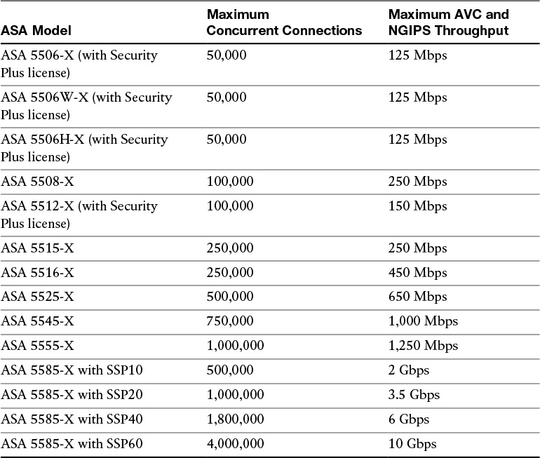
For a complete and up-to-date Cisco ASA model comparison, visit Cisco’s ASA website, at cisco.com/go/asa.
Table 2-1 The Maximum Concurrent Connections and AVC/NGIPS Throughput
Cisco ASA FirePOWER Services Licensing
You have already learned that the Cisco ASA FirePOWER module can be managed by the Firepower Management Center or ASDM, in the case of the Cisco ASA 5506-X and 5508-X. The Firepower Management Center and the Cisco ASA FirePOWER module require different licenses. These licenses are installed in the Cisco FirePOWER module and the Cisco Firepower Management Center. There are no additional licenses required in the Cisco ASA.
The following are the different types of Cisco ASA FirePOWER Services licenses:
![]() Protection
Protection
![]() Control
Control
![]() Malware
Malware
![]() URL Filtering
URL Filtering
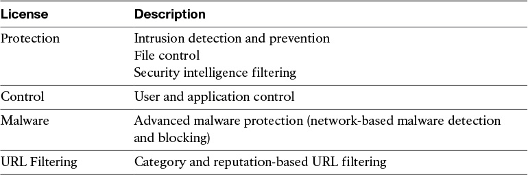
Table 2-2 provides a high-level overview of each license.
The Protection License
The Protection license enables a network security administrator to perform intrusion detection and prevention, file control, and security intelligence filtering. The intrusion detection and prevention capabilities are used to analyze network traffic for intrusions and exploits, to alert the network security administrator and optionally block offending packets. File control allows network security administrators to detect and (optionally) block users from sending or receiving files of specific types over specific application protocols.
Note
The Malware license also allows you to inspect and block a set of file types, based on malware intelligence and dispositions. The Malware license is covered later in this chapter.
Security intelligence filtering allows network security administrators to blacklist different hosts/IP addresses before the traffic is analyzed by access control rules. Cisco provides dynamic feeds, allowing a network security administrator to immediately blacklist connections based on the Cisco threat intelligence capabilities, fueled by Cisco’s research organization, Talos. You can also configure this to be monitor only.
Tip
You can configure access control policies without a license; however, if you do this, you will not be able to apply the policy until the Protection license is added to the Cisco ASA FirePOWER module. If the Protection license is for some reason deleted, the Cisco ASA FirePOWER module ceases to detect intrusions and file events, and it is not able to reach the Internet for either Cisco-provided or third-party security intelligence information.
A Protection license is required with all the other licenses (Control, Malware, and URL Filtering licenses). If the Protection license is disabled or deleted, this has a direct effect on any other licenses installed.
The Control License
The Control license allows a network security administrator to implement user and application control. The administrator does this by adding user and application settings to access control rules. As with the Protection license, you can add user and application conditions to access control rules without a Control license. You cannot apply the policy until the Control license is installed and enabled in the Cisco ASA FirePOWER module, however.
The URL Filtering License
The URL Filtering license allows a network security administrator to implement access control rules that determine what traffic can pass through the firewall, based on URLs requested by monitored hosts. The Cisco ASA FirePOWER module obtains information about those URLs from the Cisco cloud, as illustrated in Figure 2-9.
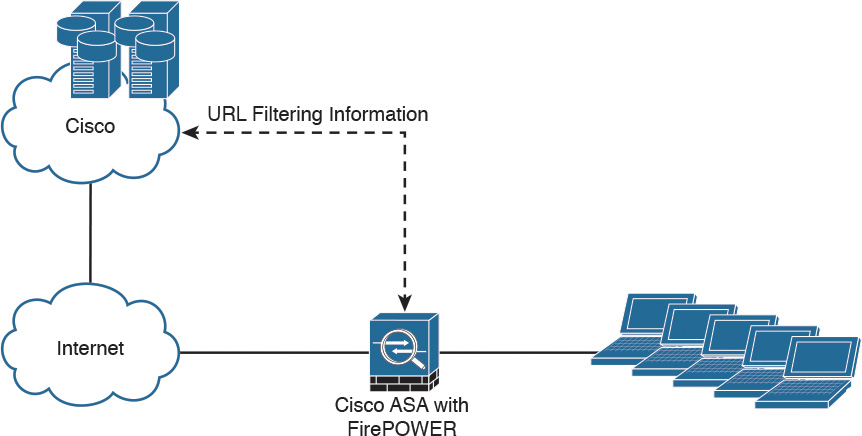
You can configure individual URLs or groups of URLs to be allowed or blocked by the Cisco ASA FirePOWER module without a URL Filtering license; however, you cannot use URL category and reputation data to filter network traffic without a URL Filtering license. The example in Figure 2-9 applies to Cisco ASA FirePOWER modules managed by ASDM. If the Cisco ASA FirePOWER module is managed by the FMC, the URL categorization and reputation information is received from Cisco by the FMC and then sent to the managed devices (that is, Cisco ASA FirePOWER modules, NGIPS, FTD, etc.).
Note
The URL Filtering license is a subscription-based license.
The Malware License
The Malware license enables Advanced Malware Protection (AMP) in the Cisco ASA FirePOWER module. With AMP you can detect and block malware potentially being transmitted over the network.
Malware detection is configured as part of a file policy, which you then associate with one or more access control rules.
Note
Step-by-step examples of how to configure the Cisco ASA FirePOWER module are provided in Chapter 3, “Configuring Cisco ASA with FirePOWER Services.”
Viewing the Installed Cisco ASA FirePOWER Module Licenses
You can view the installed licenses in the Cisco ASA FirePOWER module by navigating to System > Licenses in the Cisco Firepower Management Center. The Licenses page lists all the licenses in the devices managed by the Cisco Firepower Management Center, as shown in Figure 2-10.
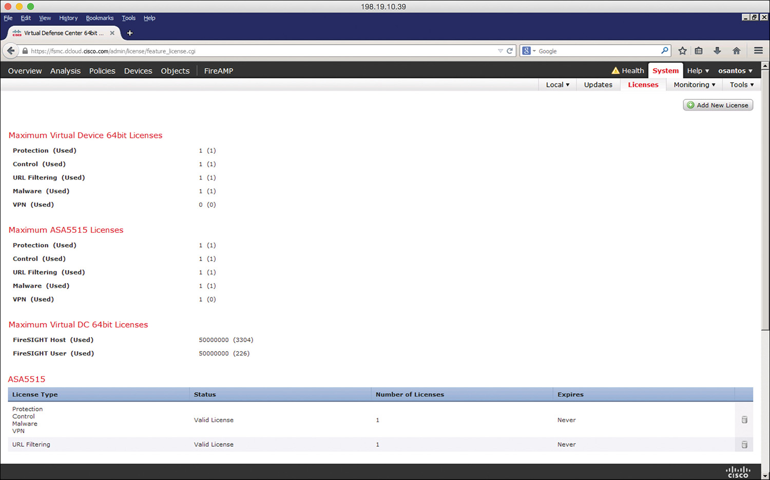
In Figure 2-10, a Cisco ASA 5515-X is being managed by the Cisco Firepower Management Center. The Protection, Control, Malware, and URL Filtering licenses are enabled.
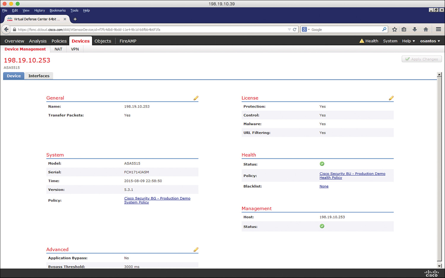
Another way to view the installed licenses in the Cisco ASA FirePOWER module is by navigating to Devices > Device Management in the Cisco Firepower Management Center. Then click the device for which you want to see the details, as shown in Figure 2-11.
Adding a License to the Cisco ASA FirePOWER Module
This section covers how to add a license to the Cisco ASA FirePOWER module after you receive the activation key provided by Cisco when you purchase the license. The following are the steps to add a license:
Step 1. Navigate to System > Licenses in the Cisco Firepower Management Center, as shown in Figure 2-12.
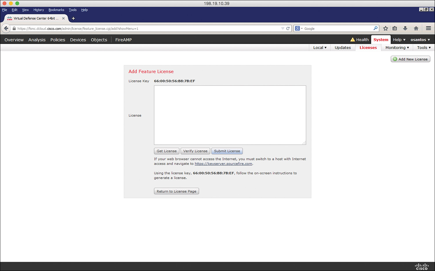
Step 2. Click Add New License on the Licenses page.
Step 3. Copy and paste the license into the License field and click Submit License. If you do not have the license, follow the instructions onscreen to obtain your license.
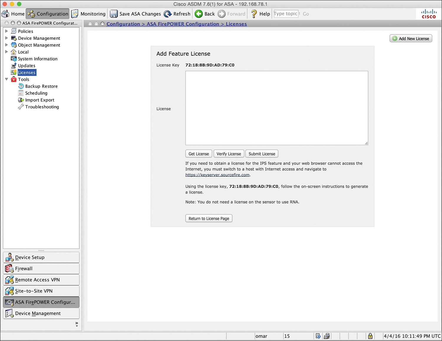
If you are configuring the Cisco ASA FirePOWER module using ASDM, you can manage and install FirePOWER licenses by navigating to Configuration > ASA FirePOWER Configuration > Licenses, as shown in Figure 2-13.
Cisco ASA FirePOWER Compatibility with Other Cisco ASA Features
The Cisco ASA FirePOWER module provides advanced HTTP inspection and other advanced application inspection features. To take advantage of these features, you do not configure traditional HTTP inspection in the Cisco ASA.
In addition, the Mobile User Security (MUS) feature is not compatible with the Cisco ASA FirePOWER module. You must disable MUS if it is enabled in the Cisco ASA.
All other Cisco ASA application inspections are compatible with the Cisco ASA FirePOWER module.
Cisco ASA FirePOWER Packet Processing Order of Operations
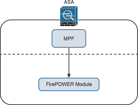
When the Cisco ASA FirePOWER module is deployed, the Cisco ASA processes all ingress packets against access control lists (ACLs), connection tables, Network Address Translation (NAT), and application inspections before traffic is forwarded to the FirePOWER Services module. In order for the Cisco ASA to redirect packets to the Cisco ASA FirePOWER module, you need to configure redirection policies using the Cisco ASA Modular Policy Framework (MPF), as illustrated in Figure 2-14.
Note
Chapter 3 covers how to configure the Cisco ASA MPF to redirect traffic to the Cisco ASA FirePOWER module.
Figure 2-15 shows the Cisco ASA packet processing order of operations.
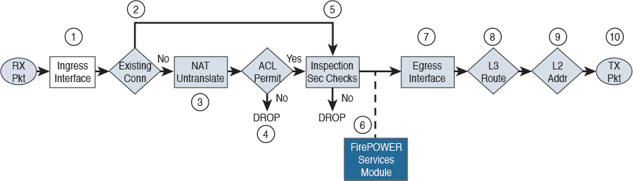
The following steps are illustrated in Figure 2-15:
Step 1. A packet is received on a given interface of the Cisco ASA. If a VPN is configured, the packet is decrypted at this point. If ACL bypass is configured for VPN traffic, the Cisco ASA proceeds to step 5.
Step 2. The Cisco ASA checks to see if there is an existing connection for the source and destination hosts for that specific traffic. If there is an existing connection, the Cisco ASA bypasses the ACL checks and performs application inspection checks and proceeds to step 5.
Step 3. If there is no existing connection for that traffic, the Cisco ASA performs the NAT checks (or untranslate process).
Step 4. The Cisco ASA allows or denies traffic based on the rules in the configured ACLs.
Step 5. If traffic is allowed, the Cisco ASA performs application inspection.
Step 6. The Cisco ASA forwards the packet to the Cisco ASA FirePOWER module. If promiscuous monitor-only mode is configured, only a copy of the packet is sent to the Cisco ASA FirePOWER module. If the Cisco ASA FirePOWER module is configured in inline mode, the packet is inspected and dropped if it does not conform to security policies. If the packet is compliant with security policies and Cisco ASA FirePOWER module protection capabilities, it is sent back to the ASA for processing.
Step 7. The Cisco ASA determines the egress interface based on NAT or Layer 3 routing.
Step 8. Layer 3 routing is performed.
Step 9. Layer 2 address lookup occurs.
Step 10. The packet is sent to the network.
Figure 2-16 shows the packet flow in the Cisco ASA 5585-X.
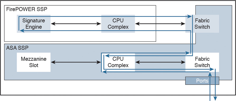
In Cisco ASA 5585-X appliances, the SSP running Cisco ASA software processes all ingress and egress packets. No packets are directly processed by the Cisco ASA FirePOWER module (SSP) except for the Cisco ASA FirePOWER module management port.
Cisco ASA FirePOWER Services and Failover
The Cisco ASA supports high availability using failover and clustering. This section covers the deployment of the Cisco ASA FirePOWER module in failover scenarios. Clustering is covered later in this chapter.
The Cisco ASA supports two types of failover:
![]() Active/standby
Active/standby
![]() Active/active
Active/active
In active/standby failover, one unit in a failover pair is always active, and the other one is in standby. Figure 2-17 illustrates active/standby failover.
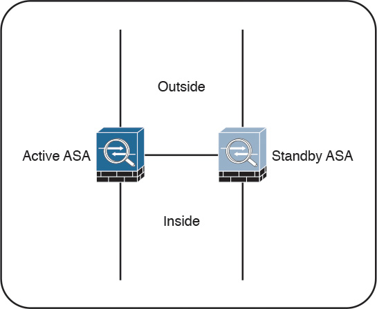
The standby device drops all transit traffic that it may receive and accepts only management connections. For a switchover to occur automatically, the active unit must become less operationally healthy than the standby. The failover event moves all transit traffic to the peer device, even if the actual impact on the previously active unit is localized. When running in multiple-context mode, all contexts switch over at the same time. Active/standby failover is the only option when running in single-context mode.
What are these so-called security contexts? Security contexts enable a physical Cisco ASA to be partitioned into multiple standalone firewalls. Each context acts and behaves as an independent entity, with its own configuration, interfaces, security policies, routing table, and administrators. The following are some examples of scenarios in which security contexts are useful in network deployments:
![]() You act as a service provider and want to provide firewall services to customers; however, you do not want to purchase additional physical firewalls for each client.
You act as a service provider and want to provide firewall services to customers; however, you do not want to purchase additional physical firewalls for each client.
![]() You manage an educational institution and want to segregate student networks from faculty networks for improved security while using one physical security appliance.
You manage an educational institution and want to segregate student networks from faculty networks for improved security while using one physical security appliance.
![]() You administer a large enterprise with different departmental groups, and each department wants to implement its own security policies.
You administer a large enterprise with different departmental groups, and each department wants to implement its own security policies.
![]() You have overlapping networks in your organization and want to provide firewall services to all those networks without changing the addressing scheme.
You have overlapping networks in your organization and want to provide firewall services to all those networks without changing the addressing scheme.
![]() You currently manage many physical firewalls, and you want to integrate security policies from all firewalls into one physical firewall.
You currently manage many physical firewalls, and you want to integrate security policies from all firewalls into one physical firewall.
![]() You manage a data center environment and want to provide end-to-end virtualization to reduce operational costs and increase efficiency.
You manage a data center environment and want to provide end-to-end virtualization to reduce operational costs and increase efficiency.
The responsibilities of the active unit include the following items:
![]() Accept configuration commands from the user and replicate them to the standby peer. All management and monitoring of a failover pair should happen on the active unit because configuration replication is not a two-way process. Making any changes on the standby ASA causes configuration inconsistency that may prevent subsequent command synchronization and create issues after a switchover event. If you inadvertently made a change on the standby device, exit the configuration mode and issue the write standby command on the active unit to restore the proper state. This command completely overwrites the existing running configuration of the standby unit with the running configuration of the active ASA.
Accept configuration commands from the user and replicate them to the standby peer. All management and monitoring of a failover pair should happen on the active unit because configuration replication is not a two-way process. Making any changes on the standby ASA causes configuration inconsistency that may prevent subsequent command synchronization and create issues after a switchover event. If you inadvertently made a change on the standby device, exit the configuration mode and issue the write standby command on the active unit to restore the proper state. This command completely overwrites the existing running configuration of the standby unit with the running configuration of the active ASA.
![]() Process all transit traffic, apply configured security policies, build and tear down connections, and synchronize the connection information to the standby unit, if configured for stateful failover.
Process all transit traffic, apply configured security policies, build and tear down connections, and synchronize the connection information to the standby unit, if configured for stateful failover.
![]() Send NetFlow Secure Event Logging (NSEL) and syslog messages to the configured event collectors. When necessary, you may configure the standby unit to transmit syslog messages with the logging standby command. Keep in mind that this command doubles the connection-related syslog traffic from the failover pair.
Send NetFlow Secure Event Logging (NSEL) and syslog messages to the configured event collectors. When necessary, you may configure the standby unit to transmit syslog messages with the logging standby command. Keep in mind that this command doubles the connection-related syslog traffic from the failover pair.
![]() Build and maintain dynamic routing adjacencies. The standby unit never participates in dynamic routing.
Build and maintain dynamic routing adjacencies. The standby unit never participates in dynamic routing.
By default, failover operates in a stateless manner. In this configuration, the active unit only synchronizes its configuration to the standby device. All the stateful flow information remains local to the active ASA, so all connections must reestablish upon a failover event. While this configuration preserves ASA processing resources, most high-availability configurations require stateful failover. To pass state information to the standby ASA, you must configure a stateful failover link.
Stateful failover is not available on the Cisco ASA 5505 platform. When stateful replication is enabled, an active ASA synchronizes the following additional information to the standby peer:
![]() Stateful table for TCP and UDP connections. To preserve processing resources, ASA does not synchronize certain short-lived connections by default. For example, HTTP connections over TCP port 80 remain stateless unless you configure the failover replication http command. Similarly, ICMP connections synchronize only in active/active failover with asymmetric routing (ASR) groups configured. Note that enabling stateful replication for all connections may cause up to a 30 percent reduction in the maximum connection setup rate supported by the particular ASA platform.
Stateful table for TCP and UDP connections. To preserve processing resources, ASA does not synchronize certain short-lived connections by default. For example, HTTP connections over TCP port 80 remain stateless unless you configure the failover replication http command. Similarly, ICMP connections synchronize only in active/active failover with asymmetric routing (ASR) groups configured. Note that enabling stateful replication for all connections may cause up to a 30 percent reduction in the maximum connection setup rate supported by the particular ASA platform.
![]() ARP table and bridge-group MAC mapping table when running in transparent mode.
ARP table and bridge-group MAC mapping table when running in transparent mode.
![]() Routing table, including any dynamically learned routes. All dynamic routing adjacencies must reestablish after a failover event, but the new active unit continues to forward traffic based on the previous routing table state until full reconvergence.
Routing table, including any dynamically learned routes. All dynamic routing adjacencies must reestablish after a failover event, but the new active unit continues to forward traffic based on the previous routing table state until full reconvergence.
![]() Certain application inspection data, such as General Packet Radio Service (GPRS), GPRS Tunneling Protocol (GTP), Packet Data Protocol (PDP), and Session Initiation Protocol (SIP) signaling tables. Keep in mind that most application inspection engines do not synchronize their databases because of resource constraints and complexity, so such connections switch over at the Layer 4 level only. As the result, some of these connections may have to reestablish after a failover event.
Certain application inspection data, such as General Packet Radio Service (GPRS), GPRS Tunneling Protocol (GTP), Packet Data Protocol (PDP), and Session Initiation Protocol (SIP) signaling tables. Keep in mind that most application inspection engines do not synchronize their databases because of resource constraints and complexity, so such connections switch over at the Layer 4 level only. As the result, some of these connections may have to reestablish after a failover event.
![]() Most VPN data structures, including security associations (SA) for site-to-site tunnels and remote-access users. Only some clientless SSL VPN information remains stateless.
Most VPN data structures, including security associations (SA) for site-to-site tunnels and remote-access users. Only some clientless SSL VPN information remains stateless.
Stateful failover supports only Cisco ASA software features. The Cisco ASA FirePOWER module tracks connection state independently, and the Cisco ASAs do not synchronize their configuration or any other stateful data in failover. When a Cisco ASA switchover occurs, the Cisco ASA FirePOWER module typically recovers existing connections transparently to the user, but some advanced security checks may apply only to new flows that are established through the newly active Cisco ASA and its local application module.
In active/active failover, Cisco ASAs operate in multiple-context mode. In this configuration, the traffic load is split between members of the failover pair so that each unit is active for some set of security contexts. This way, both failover peers are passing traffic concurrently and fully utilizing their respective hardware resources.
Figure 2-18 illustrates active/active failover.
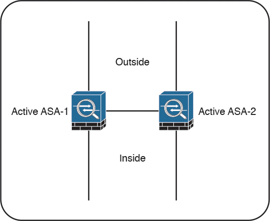
This separation is achieved by assigning specific application contexts to one of the two failover groups and then making each of the failover peers own one of these groups. As opposed to active/standby failover, where all contexts switch over to the peer on active unit failure, this model localizes the impact to the contexts in a particular failover group.
In total, an ASA supports three failover groups when configured for active/active failover:
![]() Group 0: This is a hidden, nonconfigurable group that covers only the system context. It is always active on the same unit that is active for group 1.
Group 0: This is a hidden, nonconfigurable group that covers only the system context. It is always active on the same unit that is active for group 1.
![]() Group 1: All newly created contexts belong to this group by default. The admin context must always be a member of this group. By default, the primary unit owns this group, and you typically keep it this way.
Group 1: All newly created contexts belong to this group by default. The admin context must always be a member of this group. By default, the primary unit owns this group, and you typically keep it this way.
![]() Group 2: Use this group to assign some contexts to be active on the secondary unit. The primary unit also owns this group by default, so you have to change its ownership to the secondary ASA after assigning all the desired contexts. Keep in mind that both groups have to be active on the same unit in order to move contexts between groups 1 and 2.
Group 2: Use this group to assign some contexts to be active on the secondary unit. The primary unit also owns this group by default, so you have to change its ownership to the secondary ASA after assigning all the desired contexts. Keep in mind that both groups have to be active on the same unit in order to move contexts between groups 1 and 2.
You should deploy active/active failover only when you can effectively separate the network traffic flows into these two independent groups. Keep in mind that interface sharing is not supported between contexts that belong to different failover groups.
Although active/active failover offers some load-sharing benefits, consider the following implications of this model:
![]() You must be able to separate the traffic flows into multiple contexts such that no interfaces are shared between contexts in different failover groups. Keep in mind that not all features are supported in multiple-context mode.
You must be able to separate the traffic flows into multiple contexts such that no interfaces are shared between contexts in different failover groups. Keep in mind that not all features are supported in multiple-context mode.
![]() If a switchover occurs, a single physical device must carry the full traffic load that was originally intended for two ASA units. This effectively reduces the benefits of load balancing because you should only plan the overall load on the failover pair for this worst-case scenario with a single remaining unit.
If a switchover occurs, a single physical device must carry the full traffic load that was originally intended for two ASA units. This effectively reduces the benefits of load balancing because you should only plan the overall load on the failover pair for this worst-case scenario with a single remaining unit.
![]() When using stateful failover, the standby device requires as much processing power as the active one to create new connections; the only difference is that the standby unit does not have to accept transit traffic from the network. When you enable stateful replication with active/active failover, you significantly reduce the available processing capacity of each failover pair member.
When using stateful failover, the standby device requires as much processing power as the active one to create new connections; the only difference is that the standby unit does not have to accept transit traffic from the network. When you enable stateful replication with active/active failover, you significantly reduce the available processing capacity of each failover pair member.
Generally speaking, active/standby is the preferred deployment model for failover. Consider clustering instead of active/active failover when your ASA deployment scenario requires load sharing.
What Happens When the Cisco ASA FirePOWER Module Fails?
If the Cisco ASA FirePOWER module fails, you can configure it to do either of the following:
![]() Fail open
Fail open
![]() Fail close
Fail close
When the Cisco ASA FirePOWER module is configured to fail open, all traffic still passes through the Cisco ASA if the module fails. In contrast, when the Cisco ASA FirePOWER module is configured to fail close, all traffic stops through the Cisco ASA if the module fails.
Cisco ASA FirePOWER Services and Clustering
You can configure up to 16 identical Cisco ASA appliances in a cluster to act as a combined traffic-processing system. When clustering is enabled, the Cisco ASAs preserve the benefits of failover. In a cluster, virtual IP and MAC addresses are used for first-hop redundancy.
All cluster members must have identical hardware configuration, SSP types, application modules, and interface cards.
Figure 2-19 illustrates three Cisco ASAs configured in a cluster.
In a Cisco ASA cluster, the configuration is mirrored to all members, and connection state is preserved after a single member failure.
Clustered Cisco ASA provides flow symmetry and high availability to the Cisco ASA FirePOWER module. Packets and flows are not dropped by the Cisco ASA FirePOWER module but instead are marked for “drop” or “drop with TCP reset” and sent back to the corresponding Cisco ASA. This methodology allows the Cisco ASA to clear the connection from the state tables and send TCP resets, if needed.
When clustering is configured, stateless load balancing is done via IP routing or spanned EtherChannel with the Link Aggregation Control Protocol (LACP). In addition, all Cisco ASA appliances are connected to the same subnet on each logical interface.
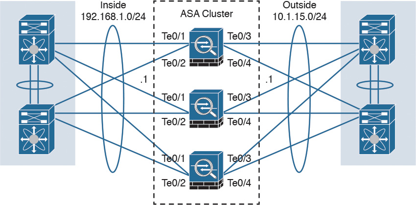
Figure 2-20 shows a Cisco ASA cluster configured with spanned EtherChannel.
You can also configure a cluster in individual interface mode. Individual interface mode is supported in Cisco ASAs configured in routed (Layer 3) mode only. It is not supported in Cisco ASAs configured in transparent (Layer 2) mode.
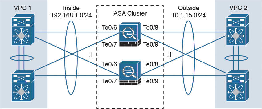
Figure 2-21 shows a Cisco ASA cluster configured in individual interface mode.
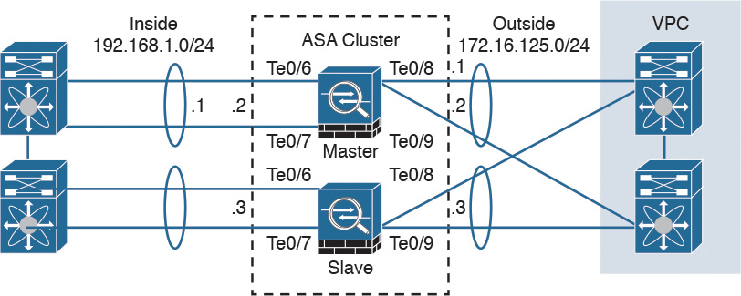
In individual interface mode, the cluster master owns the virtual IP on data interfaces for management purposes only. All members get data interface IP addresses from IP address pools in the order in which they join the cluster.
Cluster Member Election
When Cisco ASAs are configured in a cluster, one member is elected as the master, and other Cisco ASAs are slaves. The master may be the first unit to join the cluster or may be based on a configured priority. A new master is elected only if the elected master fails. The master unit handles all management and centralized functions, and the configuration is locked on slaves.
Figure 2-22 illustrates the steps in the cluster master election process.
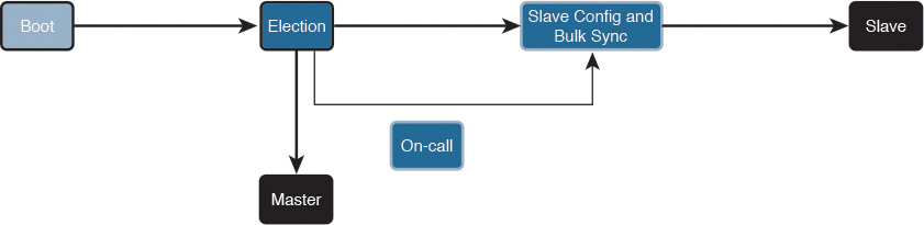
The following steps are illustrated in Figure 2-22:
Step 1. A Cisco ASA with clustering enabled boots and immediately looks for a master within the cluster.
Step 2. It waits 45 seconds before it receives a reply from a master. If no master is found, it assumes the role of master in the cluster.
Step 3. If a master already exists, the Cisco ASA assumes the role of slave and synchronizes the configuration with the master Cisco ASA.
Step 4. The master admits one unit at a time.
Step 5. The cluster slave is ready to pass traffic.
There is a virtual IP address ownership for to-the-cluster connections, and the master and slaves process all regular transit connections equally. If a master fails, management traffic and other centralized connections must be reestablished upon master failure.
How Connections Are Established and Tracked in a Cluster
This section explains how connections are established and tracked in a Cisco ASA cluster configuration.
How a New TCP Connection Is Established and Tracked in a Cluster
Figure 2-23 illustrates how a new TCP connection is established and tracked within a cluster.
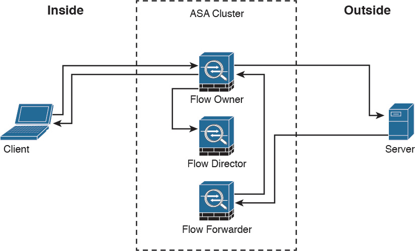
The following steps are illustrated in Figure 2-23:
Step 1. A new TCP connection attempt is received from the client (TCP SYN packet).
Step 2. The Cisco ASA that receives the TCP SYN (connection attempt) becomes the flow owner and adds the TCP SYN cookie. It then delivers the packet to the server.
Step 3. The server may reply with a TCP SYN ACK (response) through another unit in the cluster.
Step 4. If another Cisco ASA in the cluster receives the response, it forwards the packet to the flow owner and becomes the flow forwarder.
Step 5. The flow owner delivers the TCP SYN to the client.
Step 6. The flow owner updates the flow director with the connection information.
How a New UDP-Like Connection Is Established and Tracked in a Cluster
Figure 2-24 illustrates how a new UDP or another pseudo-stateful connection is established and tracked within a cluster.
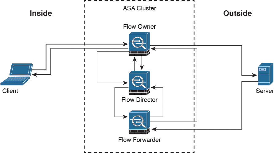
The following steps are illustrated in Figure 2-24:
Step 1. A new UDP or another pseudo-stateful connection attempt is received from the client.
Step 2. The Cisco ASA that receives the connection attempt queries the flow director to see if a connection already exists for that host.
Step 3. The Cisco ASA that received the packet becomes the flow owner if no connection was found.
Step 4. The packet is delivered to the server.
Step 5. The flow owner updates the director with the new connection information.
Step 6. The server responds to the client. If another Cisco ASA in the cluster receives the response, it forwards the packet to the flow owner and becomes the flow forwarder.
Step 7. The flow forwarder queries the director to see what Cisco ASA is the flow owner.
Step 8. The director updates the flow forwarder with the flow owner information.
Step 9. The flow forwarder forwards the server response to the flow owner.
Step 10. The server response is delivered to the client.
Centralized Connections in a Cluster
There are several Cisco ASA features where connections are centralized, such as VPN management, application inspection, and AAA for network access. If a feature is handled in a centralized way, the cluster master controls all the tasks.
Note
Packets for a nondistributed protocol inspection would have to all be forwarded to the cluster master for processing.
Centralized connections decrease overall cluster performance because they increase the processing and packet forwarding required to complete the given task.
Note
All features that are handled in a centralized way have flows always residing on the master unit in the cluster.
Figure 2-25 illustrates how a new centralized connection is established and tracked within a cluster.
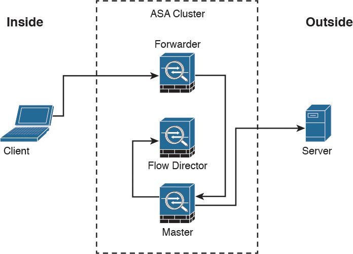
The following steps are illustrated in Figure 2-25:
Step 1. A new connection attempt is received from the client.
Step 2. The Cisco ASA that receives the connection attempt recognizes the centralized feature and redirects the connection attempt to the master.
Step 3. The master becomes the owner and delivers the packet to the server.
Step 4. The master updates the director with the connection information.
What Happens When the Flow Owner Fails
The Cisco ASA clustering feature provides high availability and redundancy. Figure 2-26 illustrates what happens when a flow owner fails for some reason.
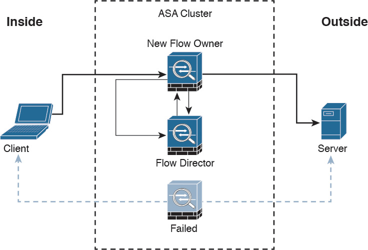
The following steps are illustrated in Figure 2-26:
Step 1. A connection is already established between the client and the server.
Step 2. The flow owner fails. This can be because of a power failure, hardware failure, or some other event, such as a system crash.
Step 3. The client sends the next packet to the server, and another cluster member receives the packet.
Step 4. The Cisco ASA that receives the packet queries the director.
Step 5. The director detects that the original flow owner failed and assigns a new owner.
Step 6. The packet is delivered to the server.
Step 7. The new flow owner updates the flow director.
Deploying the Cisco ASA FirePOWER Services in the Internet Edge
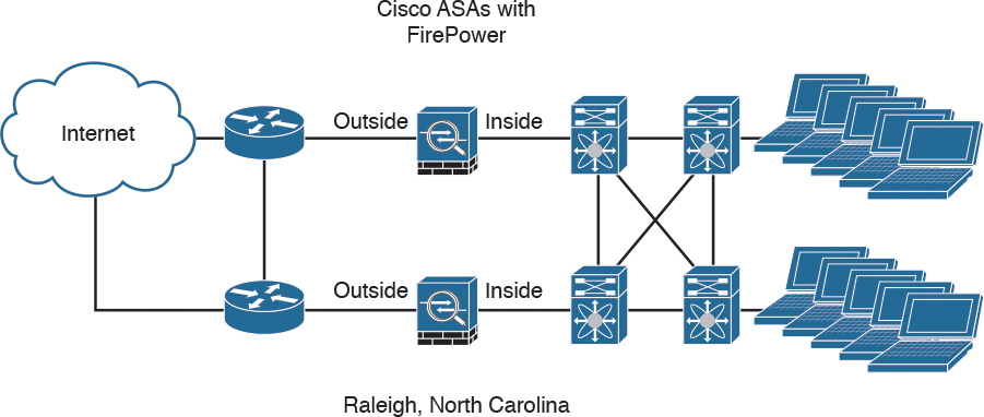
The Cisco ASA FirePOWER module provides unprecedented capabilities to protect a corporate network from Internet threats. Many organizations of all sizes deploy the Cisco ASA FirePOWER module at their Internet edge. Figure 2-27 illustrates a pair of Cisco ASA with FirePOWER modules deployed in the Internet edge of a corporate office in Raleigh, North Carolina.
Deploying the Cisco ASA FirePOWER Services in VPN Scenarios
The Cisco ASA FirePOWER module can be deployed in site-to-site and remote-access VPN environments. As you learned earlier in this chapter, the decryption process takes place before the packets are sent to the Cisco ASA FirePOWER module by the Cisco ASA, and the packets are encrypted after they are inspected by the Cisco ASA FirePOWER module and sent back to the Cisco ASA.
Figure 2-28 illustrates how a Cisco ASA with the FirePOWER module is deployed in an office in New York, terminating SSL and IPsec (IKEv2) VPN tunnels from remote clients in the Internet.
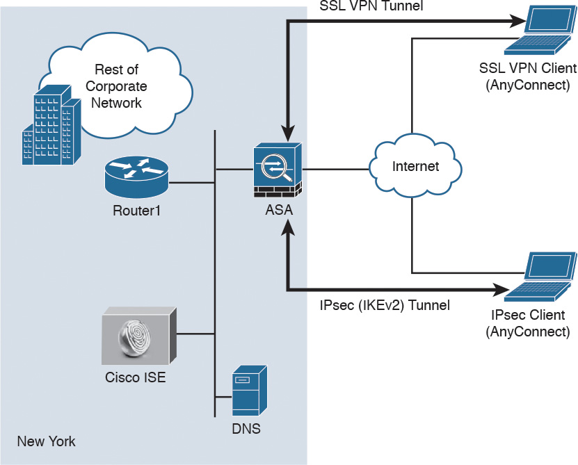
In the example illustrated in Figure 2-28, the remote-access VPN clients are using the Cisco AnyConnect client; however, clientless SSL VPN is also supported.
Figure 2-29 illustrates how two Cisco ASAs with FirePOWER modules are deployed in the headquarters office in New York (ASA 1) and a branch office in Raleigh, North Carolina (ASA 2), establishing a site-to-site IPsec VPN tunnel. In addition, ASA 2 in New York is also terminating a site-to-site IPsec VPN tunnel to a router (R1) of a business partner in Las Vegas.
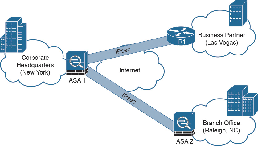
In the example illustrated in Figure 2-29, the Cisco ASA FirePOWER module not only protects against threats in the corporate network in the remote branch office but also protects against threats coming from an unmanaged business partner.
Deploying Cisco ASA FirePOWER Services in the Data Center
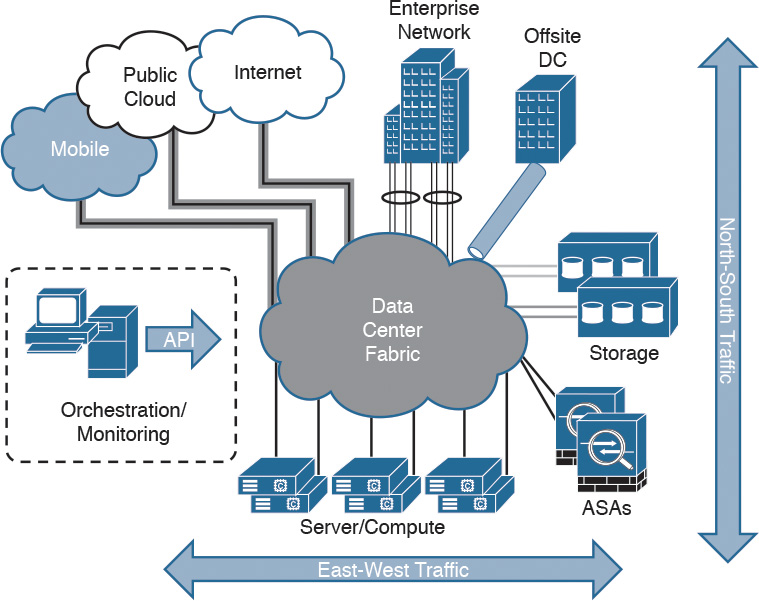
The data center can be a very complex world. It not only provides a rich set of services and architectures but also hosts the crown jewels of an organization. It is extremely important to maintain visibility of everything that is happening in the data center. The concept of “north-to-south” and “east-to-west” is often used in describing the types of communication (or flow) within and to the outside of the data center:
![]() North-to-south describes communication between end users and external entities.
North-to-south describes communication between end users and external entities.
![]() East-to-west describes communication between entities in the data center.
East-to-west describes communication between entities in the data center.
Figure 2-30 illustrates the concepts of north-to-south and east-to-west communication.
The data center has many different high-throughput and low-latency requirements, in addition to increased high-availability requirements. In addition, automated provisioning and control with orchestration, monitoring, and management tools are crucial.
The data center architecture consists of three primary modular layers with hierarchical interdependencies:
![]() Data center foundation: This is the primary building block of the data center, on which all other services rely. Regardless of the size of the data center, the foundation must be resilient, scalable, and flexible to support data center services that add value, performance, and reliability. The data center foundation provides the computing necessary to support the applications that process information and the seamless transport between servers, storage, and the end users who access the applications.
Data center foundation: This is the primary building block of the data center, on which all other services rely. Regardless of the size of the data center, the foundation must be resilient, scalable, and flexible to support data center services that add value, performance, and reliability. The data center foundation provides the computing necessary to support the applications that process information and the seamless transport between servers, storage, and the end users who access the applications.
![]() Data center services: These services include infrastructure components to enhance the security of the applications and access to critical data. They also include virtual switching services to extend the network control in a seamless manner from the foundation network into the hypervisor systems on servers to increase control and reduce operational costs (as well as other application resilience services).
Data center services: These services include infrastructure components to enhance the security of the applications and access to critical data. They also include virtual switching services to extend the network control in a seamless manner from the foundation network into the hypervisor systems on servers to increase control and reduce operational costs (as well as other application resilience services).
![]() User services: These services include email, order processing, and file sharing or any other applications in the data center that rely on the data center foundation and services, like database applications, modeling, and transaction processing.
User services: These services include email, order processing, and file sharing or any other applications in the data center that rely on the data center foundation and services, like database applications, modeling, and transaction processing.
Figure 2-31 illustrates some of the components of the data center services architecture.
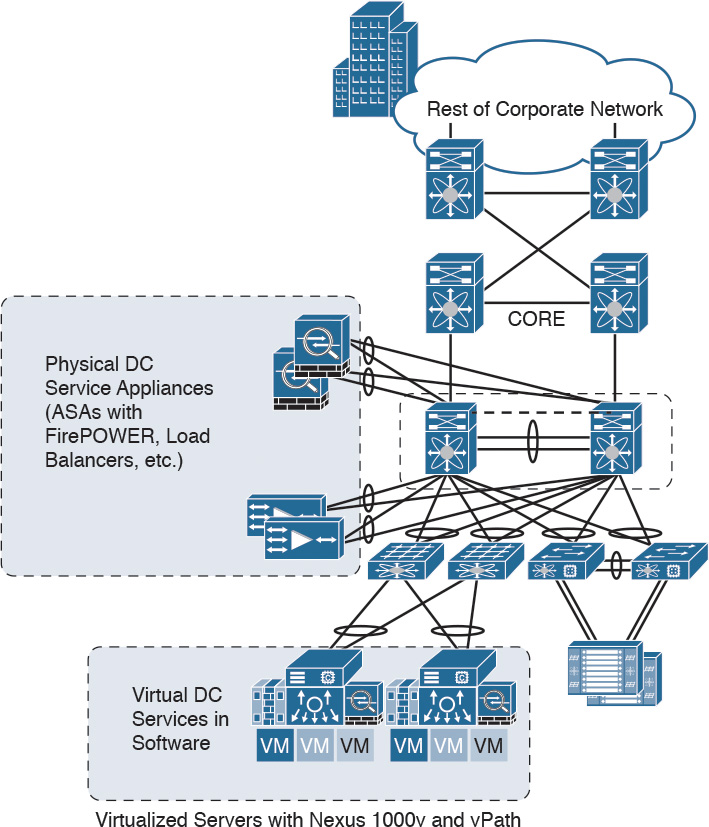
Examples of the data center service insertion components include the following:
![]() Firewalls (In the example illustrated in Figure 2-31, Cisco ASAs with FirePOWER modules are deployed.)
Firewalls (In the example illustrated in Figure 2-31, Cisco ASAs with FirePOWER modules are deployed.)
![]() Intrusion prevention systems (IPS)
Intrusion prevention systems (IPS)
![]() Application delivery features
Application delivery features
![]() Server load balancing
Server load balancing
![]() Network analysis tools (such as NetFlow)
Network analysis tools (such as NetFlow)
![]() Virtualized services deployed in a distributed manner along with virtual machines
Virtualized services deployed in a distributed manner along with virtual machines
![]() Traffic direction with vPath and Nexus 1000v
Traffic direction with vPath and Nexus 1000v
![]() Application Centric Infrastructure (ACI) automated framework components for service insertion
Application Centric Infrastructure (ACI) automated framework components for service insertion
In the case of virtualized environments, the Cisco ASAv (virtual machine) can be deployed to protect VM-to-VM communication. The Cisco ASA FirePOWER module in these environments is not supported, as the Cisco ASAv is just a virtual machine. Cisco FirePOWER virtual machines running network AMP can be deployed in those scenarios.
The Cisco ASAv supports both traditional tiered data center deployments and the fabric-based deployments of Cisco ACI environments. The Cisco ASAv can also be deployed in cloud environments like Amazon Web Services (AWS).
The Cisco ASA with FirePOWER modules can be deployed in geographically dispersed cluster environments.
Figure 2-32 shows an example in which four Cisco ASAs with FirePOWER modules are deployed in two separate sites (site A and site B).
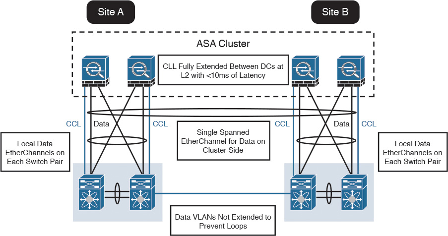
In the example illustrated in Figure 2-32, the cluster of four Cisco ASAs is fully extended between the two data centers, using the cluster control links (CCL) operating at Layer 2 with a latency of less than 10 milliseconds. A single spanned EtherChannel for transient data is used on the cluster side. The local data links are also configured with EtherChannels at the switch pairs on each site.
Tip
The data VLANs between the switches are not extended to prevent network loops.
Firepower Threat Defense (FTD)
In Chapter 1 you learned that Firepower Threat Defense software is unified software that provides next-generation firewall services, including the following:
![]() Stateful firewall capabilities
Stateful firewall capabilities
![]() Static and dynamic routing
Static and dynamic routing
![]() Next-generation intrusion prevention systems (NGIPS)
Next-generation intrusion prevention systems (NGIPS)
![]() Application visibility and control (AVC)
Application visibility and control (AVC)
![]() URL filtering
URL filtering
![]() Advanced Malware Protection (AMP)
Advanced Malware Protection (AMP)
In the Cisco ASA, you can use FTD in single context mode and in routed or transparent mode. Multiple context mode is not supported at this writing.
The following are the Cisco ASA 5500-X models that support a reimage to run the FTD software:
![]() ASA 5506-X
ASA 5506-X
![]() ASA 5506W-X
ASA 5506W-X
![]() ASA 5506H-X
ASA 5506H-X
![]() ASA 5508-X
ASA 5508-X
![]() ASA 5512-X
ASA 5512-X
![]() ASA 5515-X
ASA 5515-X
![]() ASA 5516-X
ASA 5516-X
![]() ASA 5525-X
ASA 5525-X
![]() ASA 5545-X
ASA 5545-X
![]() ASA 5555-X
ASA 5555-X
To reimage one of the aforementioned Cisco ASA models, you must meet the following prerequisites:
![]() You must have a Cisco Smart Account. You can create one at Cisco Software Central (https://software.cisco.com).
You must have a Cisco Smart Account. You can create one at Cisco Software Central (https://software.cisco.com).
![]() You need to review the FTD software version release notes to become familiar of the supported features, as Cisco continues to add features very regularly.
You need to review the FTD software version release notes to become familiar of the supported features, as Cisco continues to add features very regularly.
![]() Add at least a base FTD license to your Smart Account (for example, L-ASA5516T-BASE=).
Add at least a base FTD license to your Smart Account (for example, L-ASA5516T-BASE=).
![]() You must have access to an FMC (virtual or physical).
You must have access to an FMC (virtual or physical).
![]() You must have access to the console port of the Cisco 5500-X appliance on which FTD software will be installed, either directly from the computer being used for installing FTD software or through a terminal server.
You must have access to the console port of the Cisco 5500-X appliance on which FTD software will be installed, either directly from the computer being used for installing FTD software or through a terminal server.
![]() It is a best practice to back up your existing configuration.
It is a best practice to back up your existing configuration.
![]() Understand that when you reimage and install FTD software on your Cisco ASA, all previous files and configurations saved on the ASA are lost.
Understand that when you reimage and install FTD software on your Cisco ASA, all previous files and configurations saved on the ASA are lost.
![]() You need to have the required minimum free space (3 GB plus the size of the boot software) available on the flash (disk0).
You need to have the required minimum free space (3 GB plus the size of the boot software) available on the flash (disk0).
![]() You must have an SSD in your Cisco ASA.
You must have an SSD in your Cisco ASA.
![]() You must have access to a TFTP server to host the FTD images.
You must have access to a TFTP server to host the FTD images.
In Chapter 3, you will learn how to reimage and install the FTD software in supported Cisco ASA models.
Summary
The Cisco ASA FirePOWER module provides network visibility, policy enforcement, and advanced threat protection across many organizations and the entire attack continuum. This chapter starts with an introduction to the Cisco ASA FirePOWER module. It explains the difference between inline and promiscuous (monitor-only) deployment modes. This chapter also covers the different Cisco ASA FirePOWER management options and provides guidance on what models to use, based on network size and demands. You have also learned about the Cisco ASA FirePOWER Services licensing and compatibility issues with other Cisco ASA features. This chapter also provides a deep dive into the Cisco ASA and the Cisco FirePOWER module packet-processing order of operations. You have learned how the Cisco ASA FirePOWER module behaves and is deployed in failover and clustering configurations. Several deployment scenarios are covered, including deploying Cisco ASA FirePOWER Services at the Internet Edge, in site-to-site and remote-access VPN scenarios, and in the data center. At the end of the chapter, you learned a few details about the FTD software and prerequisites prior to installation on a supported Cisco ASA model.