
We have finally reached the end of our journey. In this chapter, we will look at methods of planning and designing your own algorithms. As a business manager, student, or someone who may have to work with programmers or code, you need a way to communicate your thoughts and ideas to the people who will be implementing the design. You can design algorithms for your own use or for use by a programmer. What I will do in this chapter is to teach you the process and tools you can use for planning and designing your own algorithms that can then be implemented by you or someone else.
The Need for Proper Planning and Design
Before you begin to do anything, you must have a proper plan in place that can be executed. Buildings, cars, bridges, and airplanes all had system designers who envisioned what the final product would look like long before the first cement was poured or the first joint was welded.
In the realm of computer science, however, it is commonplace that many “coders” will open a terminal and start typing code. The result is that you wind up a program that has poor logical structure and is troublesome for anyone trying to read your program to understand. You see people fail to realize that the act of writing code (coding) is not the same as programming and writing proper programs.
To fix this problem, we will approach our algorithm design like a computer scientist, not like a coder. By having a proper method detailing how your algorithm will be implemented, you will be able to design algorithms that are modular, meaning that they will be able to be implemented in any programming language and be used across a wide variety of programs. Take the algorithms and data structures presented in this book; they can be implemented and used in any programming language and adapted to a multitude of paradigms and applications.
Another reason to plan and design your algorithms before implementation is that the methods presented in this chapter are very abstract. Abstraction is the key to realizing the solution to complex problems. This is why in programming implementations come and go, but many of the theories of computation (Turing machines, FSMs, time complexity) have existed for what may seem like eons in the world of modern technology and will be abound for the foreseeable future. These concepts are so powerful and abstract that even though many implementations have come and gone, they have remained the same.
The Three Stages of Algorithms
Let’s take some time out to discuss what algorithms are really doing. Algorithms and basically all other computer programs have three stages. They take an input, do some processing, and then produce an output.
During the input stage, the data or information to be processed is loaded into the memory of the machine. The machine will gather this information from a hardware mechanism (an input device, sensor), or it can all come from software. Regardless of where it comes from, before entry into an algorithm, the data must be present in a form that can be processed by the algorithm.
Next, we have the processing stage. In this stage, the data that was input will be actually worked upon. We will perform calculations using the data that was input or maybe do some alteration or manipulation of the data itself (think searching and sorting). At the core of all processing is the CPU. The entire design of your machine and all supporting hardware and software components are to enable efficient operation of the CPU that does the data processing.
The final stage is to produce an output. After your algorithm does processing on the data, it ultimately sends it to some component that uses it. This may be a hardware device like a screen, transducer, or actuator. However, it may also be a software component, and the output may be utilized by another method or function that is running its own algorithm, and your algorithm may just be a cog in a large complex program.
Keep these three stages in mind as you move forward learning how to plan and design your own algorithms.
Flowcharts
The first method we will look at to design our own algorithms is the use of flowcharts. A flowchart is a diagram that we use to represent a process. Flowcharts will allow you to design your own algorithms without having to learn any programming language. Flowcharts are the preferred method of designing algorithms for people learning because they provide a simple pictorial representation of the algorithm you are designing.
Utilizing the power of flowcharts, we can iterate very quickly on our algorithm design and easily spot any logical flaws. Flowcharts also have their program flow in such a way that any modern programming language will be able to use the logic you designed.
In the next few sections, we will look at flowcharts as tools for someone designing an algorithm.
Flowchart Symbols
Before we can use flowcharts, we must become acquainted with their symbols. The flowchart symbols are simple geometric symbols that all have different meanings. In Figure 12-1, we see a list of the flowchart symbols that we will use to realize our algorithm designs.
Figure 12-1.
Flowchart symbols
Keep in mind that this flowchart list is not exhaustive; however, it is enough of a subset that you can realize almost any algorithm you can fathom and is easily transferable to any modern programming language.
Arrows
If you look at a flowchart, you will observe that there are arrows connecting everything together. See Figure 12-2.
Figure 12-2.
Arrow symbol
The arrows within a flowchart will guide someone looking at the program to be able to identify the flow of your chart logic. Arrows are a useful tool that is crucial to any flowchart design.
Terminator
The second flowchart symbol we will look at is the terminator symbol. Figure 12-3 shows use the terminator symbol.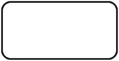
Figure 12-3.
The terminator symbol
The terminator symbol is used to indicate the start (entry) and end (termination) points within your algorithm. Your algorithm will have one starting point; however, it is not uncommon, depending on your logic flow, to have several endpoints.
It is easy to identify whether the terminator is a start point or an end point in your algorithm. Good algorithm design dictates that you place the words Start or End within the shape. Figure 12-4 shows what a start will look like, and Figure 12-5 shows an end.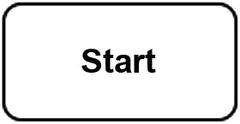

Figure 12-4.
Start terminator
Figure 12-5.
End terminator
Besides arrows, start and end terminators are two flowchart symbols you are sure to find in your program.
Input and Output
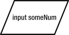
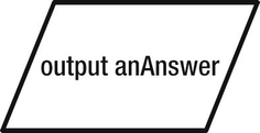
As was previously stated, algorithms have three big stages, which are input, processing, and output. In Figure 12-6 we see the geometric parallelogram shape that is used to indicate an input or an output.
Figure 12-6.
The input and output symbol
Process
The process symbol is the workhorse of flowcharting. The process symbol is used to represent basic tasks or actions in your process. Figure 12-9 shows the process symbol.
Figure 12-9.
Process symbol
The process symbol is one you will see often in a flowchart because throughout your entire algorithm you will have to take action steps.
Decision
Many times in your algorithms you will need to make a yes/no or true/false decision and then do something else based on that result. The decision symbol, as shown in Figure 12-10, is used to represent this decision.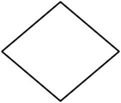
Figure 12-10.
Decision symbol
Once the flowchart determines an answer to the decision, it will take the branch of execution related to that decision.
Predefined Process
If you write every single symbol in a large algorithm in your flowchart, then it may become difficult to follow directly. For that reason, it is sometimes necessary to separate your algorithm into different modules that contain a series of process steps.
The symbol in Figure 12-11 is meant to indicate this.
Figure 12-11.
Predefined process
Program Structures
When designing your algorithms, you will notice that some structures repeat quite often. These structures are so common and useful that they have been named. The structures we will look at are the sequence, if-then, if-then-else, while, do-while, and switch.
Each of these structures will be briefly explained in the upcoming sections. The sequence structure falls into a class by itself and is known as a sequence structure
. The if-then, if-then-else, and switch structures are known as the selection or decision structures
. The while and do-while structures are known as the loop structures
.
Sequence
The first common structure you will see is the simple sequence. In the sequence, you will have a start terminator followed by a series of processes and an end terminator, as shown in Figure 12-12.
Figure 12-12.
The sequence structure
If-Then
Another common structure you can use to design your program is the if-then structure. This structure is used to make a single decision. The if-then structure is shown in Figure 12-13.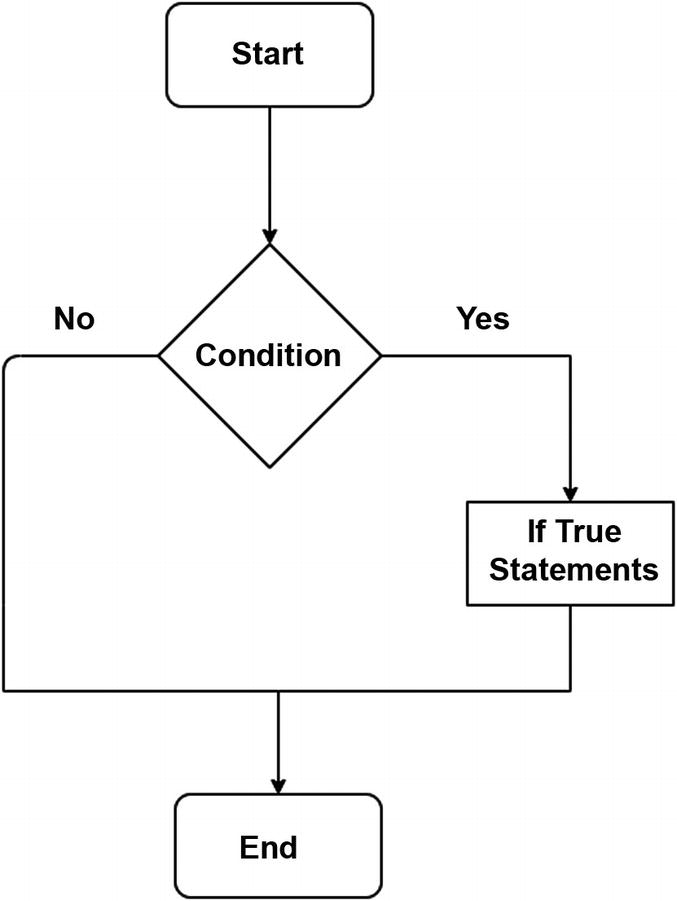
Figure 12-13.
The if-then structure
In the if-then structure you have your entry. You make a decision based on the question statement. If your decision is yes, then you will do some action in the process. If the decision is no, then you will exit the algorithm.
If-Then-Else
The if-then-else structure builds on the if-then structure. Like the if-then structure, we test a condition, and if that condition evaluates to true, we take the Yes branch, execute those statements, and then terminate. See Figure 12-14.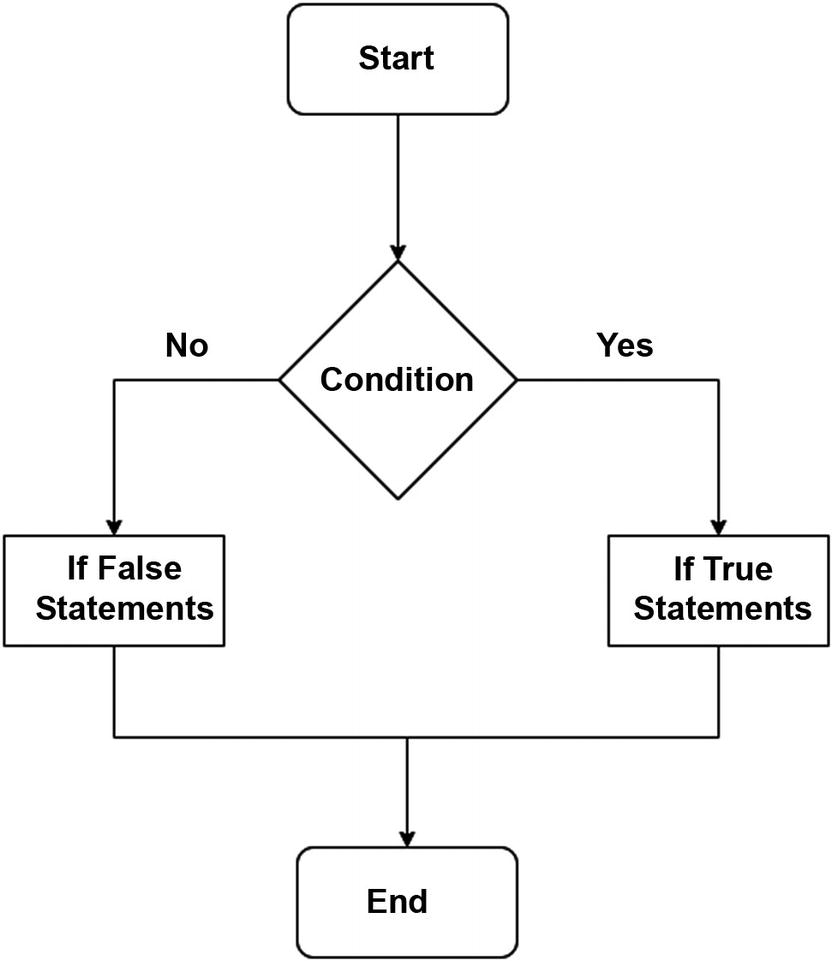
Figure 12-14.
The if-then-else
There is another facet to this structure, though. If the decision evaluates to false, instead of just exiting the structure, we take the No branch and then execute the false statements. So, if the condition is true, then execute some statements; otherwise, we execute some other statement.
While Loop
In Figure 12-15 we are presented with another structure, the while loop structure.
Figure 12-15.
The while loop
The while loop is a common structure you will encounter. In the while loop, while the test Boolean expression continues to be true, the loop will keep executing indefinitely. Therefore, for this structure, some exit condition is needed to prevent what is known as an infinite loop
from occurring where the program runs indefinitely.
Do-While Loop

This do-while loop, like the while loop, will execute a block of statements at least once. The difference between these two looping structures is that the while loop will execute the statements inside its process only if the Boolean expression is true. In the do-while loop, the process block is run at least once; then it will continue continuously executing the block once the Boolean expression is true in the same manner as the while loop.
Switch
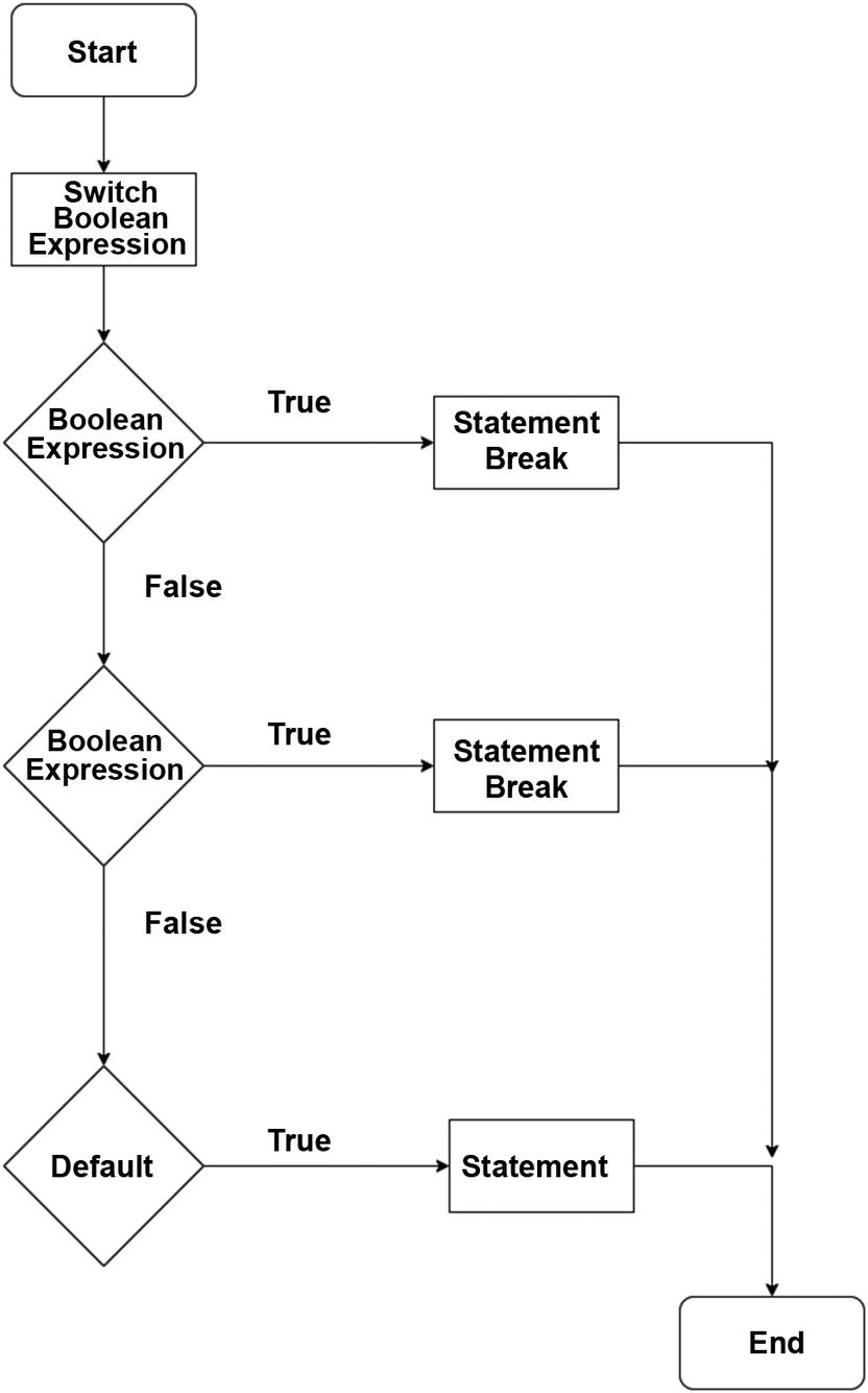
The switch case structure allows us to execute differing blocks of processes or to branch based on the value of the switch expression. If the switch control statement does not match any of the available cases, then there is usually a default case with default statements that we want to execute.
Example Algorithm Linear Search
Let’s put everything we learned so far into the linear search
algorithm, as shown in Figure 12-18.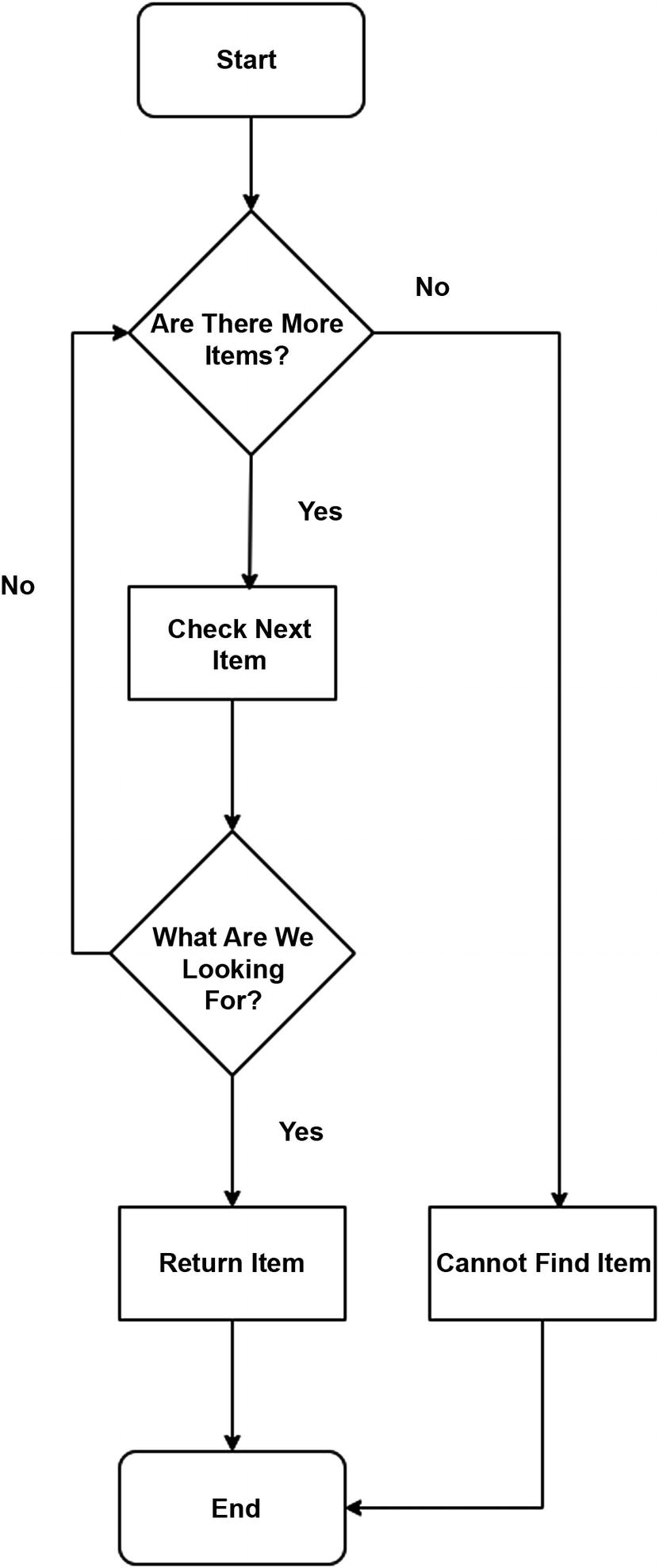
Figure 12-18.
Linear search
The linear search algorithm
, as you can follow from the flowchart, works as follows. We start with a list of items and ask, “Are there any more items we can work with?” If there are items for us to work with, we check the next item. If we found what we are looking for, we return the item, and the algorithm exits. If we did not find what we are looking for, then we return to the decision of determining whether there are more items. This continues until the “Are there more items?” decision returns false; then we take the No branch, which means that we cannot find the item.
Pseudocode
In this chapter, we learned the building blocks of algorithms using a pictorial representation of our logic
. However, there is another way we can use to describe our logic. We can use pseudocode (do you remember our little talk on pseudo in Chapter 10?). Programmers favor pseudocode as it gives them a way to use English to describe and model their logic.
Pseudocode is similar to code; however, it is written in such a way that it does not use the syntax of any one language and thus can be modeled in any language. In some implementation languages such as the Python programming language, pseudocode statements can easily be translated into statements of that programming language. Figure 12-19 shows an example of what pseudocode looks like.
Figure 12-19.
Pseudocode
The pseudocode in Figure 12-19 reads two numbers from the user: firstNumber
and secondNumber. We then store the result of their sum in another number called result and display it to the user.
Conclusion
In this chapter, we looked at various algorithm design techniques using flowcharts and also briefly discussed pseudocode. With the conclusion of this chapter, we have reached the end of the book. Congratulations! Remember, your journey doesn’t have to stop here; you can look at Appendix A to feed your hunger for more knowledge.
Good luck!