CHAPTER 2
Cabling and Topology
The CompTIA Network+ certification exam expects you to know how to
• 1.2 Explain the characteristics of network topologies and network types
• 1.3 Summarize the types of cables and connectors and explain which is the appropriate type for a solution
• 5.2 Given a scenario, troubleshoot common cable connectivity issues and select the appropriate tools
To achieve these goals, you must be able to
• Explain the different types of network topologies
• Describe the different types of network cabling and connectors
• Describe the IEEE networking standards
Every network must provide some method to get data from one system to another. In most cases, this method consists of some type of cabling running between systems, although most networks today incorporate wireless methods to move data as well. Stringing those cables brings up a number of critical issues you need to understand to work on a network. How do all these cables connect the computers? Does every computer on the network run a cable to a central point? Does a single cable snake through the ceiling, with all the computers on the network connected to it? These questions need answering!
Furthermore, manufacturers need standards so they can make networking equipment that works well together. While we’re talking about standards, what about the cabling itself? What type of cable? What quality of copper or fiber? How thick should it be? Who defines the standards for cables so they all work in the network?
This chapter answers these questions in three parts. First, you will learn about the network topology—the way that pieces of hardware connect to one another, via wires or wirelessly. Second, you will tour the most common standardized cable types used in networking. Third, you will learn about the IEEE committees that create network technology standards.
Test Specific
Network Topologies
Computer networks employ many different topologies, or ways of connecting computers and other devices like switches and printers together. This section looks at both the historical topologies—bus, ring, and star; all long dead—and the modern topologies—hybrid and mesh. In addition, we will look at what parameters are used to make up a network topology.

NOTE Wireless networks employ topologies too, just not with wires. We’ll cover the common wireless topologies—infrastructure and ad hoc—
in Chapter 14.
Bus and Ring
The first generation of wired networks used one of two topologies, both shown in Figure 2-1. A bus topology network used a single cable (i.e., the bus) that connected all the computers in a line. A ring topology network connected all computers on the network with a ring of cable.

Figure 2-1 Bus and ring topologies
NOTE Topologies are diagrams, much like an electrical circuit diagram. Real network cabling doesn’t go in perfect circles or perfect straight lines.
Data flowed differently between bus and ring networks, creating different problems and solutions. In bus topology networks, data from each computer simply went out on the whole bus. A network using a bus topology needed termination at each end of the cable to prevent a signal sent from one computer from reflecting at the ends of the cable, quickly bringing the network down (Figure 2-2).

Figure 2-2 Terminated bus topology
In a ring topology network, in contrast, data traffic moved in a circle from one computer to the next in the same direction (Figure 2-3). With no end to the cable, ring networks required no termination.

Figure 2-3 Ring topology moving in a certain direction
Bus and ring topology networks worked well but suffered from the same problem: the entire network stopped working if the cable broke at any point (Figure 2-4). The broken ends on a bus topology network didn’t have the required termination, which caused reflection between computers that were still connected. A break in a ring topology network simply broke the circuit, stopping the data flow.

Figure 2-4 Nobody is talking!
Star
The star topology, also called hub-and-spoke, used a central connection box for all the computers on the network (Figure 2-5). Star topologies had a huge benefit over ring and bus topologies by offering fault tolerance—if one of the cables broke, all of the other computers could still communicate. Bus and ring topology networks were popular and inexpensive to implement, however, so the old-style star topology networks weren’t very successful. Network hardware designers couldn’t easily redesign their existing networks to use a star topology.
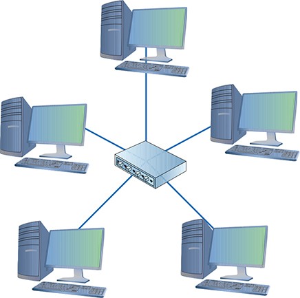
Figure 2-5 Star topology
Hybrid
Even though network designers couldn’t easily use a star topology, the benefits of star topologies were overwhelming, motivating smart people to come up with a way to use star topologies without requiring a major redesign—and the way they did so was ingenious. The ring topology network designers struck first by taking the entire ring and shrinking it into a small box, as shown in Figure 2-6.

Figure 2-6 Shrinking the ring
This was quickly followed by the bus topology folks, who, in turn, shrunk their bus (better known as the segment) into their own box (Figure 2-7).

Figure 2-7 Shrinking the segment
Physically, both of these hybrid designs looked like a star, but if you examined them as an electronic schematic, the signals acted like a ring or a bus. Clearly the old definition of topology needed a little clarification. When we talk about topology today, we separate how the cables physically look (the physical topology) from how the signals travel electronically (the signaling topology or logical topology).

EXAM TIP Most techs refer to the signaling topology as the logical topology today. That’s how you’ll see it on the CompTIA Network+ exam as well. Look for a question on the exam that challenges you on logical versus physical topology.
Any form of networking technology that combines a physical topology with a signaling topology is called a hybrid topology. Hybrid topologies have come and gone since the earliest days of networking. Only two hybrid topologies, star-ring topology and star-bus topology, ever saw any amount of popularity. Eventually, star-ring lost market share, and star-bus reigns as the undisputed “star” (pun intended) of wired network topologies.
NOTE The most successful of the star-ring topology networks was called Token Ring, manufactured by IBM.
Mesh
Topologies aren’t just for wired networks. Wireless networks also need topologies to get data from one machine to another, but using radio waves instead of cables involves somewhat different topologies. Wireless devices can connect in a mesh topology network, where every computer connects to every other computer via two or more routes. Some of the routes between two computers may require traversing through another member of the mesh network. (See Chapter 14 for the scoop on wireless network types.)
There are two types of meshed topologies: partially meshed and fully meshed (Figure 2-8). In a partially meshed topology network, at least two machines have redundant connections. Every machine doesn’t have to connect to every other machine. In a fully meshed topology network, every computer connects directly to every other computer.

Figure 2-8 Partially and fully meshed topologies
Parameters of a Topology
Although a topology describes the method by which systems in a network connect, the topology alone doesn’t describe all of the features necessary to enable those networks. The term bus topology, for example, describes a network that consists of machines connected to the network via a single linear piece of cable. Notice that this definition leaves a lot of questions unanswered. What is the cable made of? How long can it be? How do the machines decide which machine should send data at a specific moment? A network based on a bus topology can answer these questions in several ways—but it’s not the job of the topology to define issues like these. A functioning network needs a more detailed standard.
EXAM TIP Make sure you know the topologies: bus, ring, star/hub-and-spoke, hybrid, and mesh.
Over the years, manufacturers and standards bodies have created network technologies based on different topologies. A network technology is a practical application of a topology and other critical tools that provides a method to get data from one computer to another on a network. These network technologies have names like 100BASE-T, 1000BASE-LX, and 10GBASE-T. You will learn all about these in the next two chapters.
![]()
SIM Check out the excellent Chapter 2 “Topology Matching” Challenge! over at http://totalsem.com/008. It’s a good tool for reinforcing the topology variations.
Cabling and Connectors
Most networked systems link together using some type of cabling. Different types of networks over the years have used different types of cables—and you need to learn about all these cables to succeed on the CompTIA Network+ exam. This section explores scenarios where you would use common network cabling.
All cables used in the networking industry can be categorized in two distinct groups: copper and fiber-optic. All styles of cables have distinct connector types that you need to know.
Copper Cabling and Connectors
The most common form of cabling uses copper wire wrapped up in some kind of protective sheathing, thus the term copper cables. The two primary types of copper cabling used in the industry are coaxial and twisted pair.
Both cable types sport a variety of connector types. I’ll cover the connector types as I discuss the cable varieties.
Coaxial Cable
Coaxial cable contains a central copper conductor wire surrounded by an insulating material, which, in turn, is surrounded by a braided metal shield. The cable is referred to as coaxial (coax for short) because the center wire and the braided metal shield share a common axis or centerline (Figure 2-9).

Figure 2-9 Cutaway view of coaxial cable
Coaxial cable shields data transmissions from interference. Many devices in the typical office environment—including lights, fans, copy machines, and refrigerators—generate magnetic fields. When a metal wire encounters these magnetic fields, electrical current is generated along the wire. This extra current, called electromagnetic interference (EMI), can shut down a network because it is easily misinterpreted as a signal by devices like NICs. To prevent EMI from affecting the network, the outer mesh layer of a coaxial cable shields the center wire (on which the data is transmitted) from interference (Figure 2-10).

Figure 2-10 Coaxial cable showing braided metal shielding
Early bus topology networks used coaxial cable to connect computers together. Back in the day, the most popular cable used special bayonet-style connectors called BNC connectors (Figure 2-11).

Figure 2-11 BNC connector on coaxial cable
NOTE Techs all around the globe argue over the meaning of BNC. A solid percentage says with authority that it stands for “British Naval Connector.” An opposing percentage says with equal authority that it stands for “Bayonet Neill-Concelman,” after the stick-and-twist style of connecting and the purported inventors of the connector. The jury is still out, though this week I’m leaning toward Neill and Concelman and their bayonet-style connector.
You’ll find coaxial cable used today primarily to enable a cable modem to connect to an Internet service provider (ISP). That’s the typical scenario for using coaxial cable: connecting a computer to the cable modem enables that computer to access the Internet. This cable is the same type used to connect televisions to cable boxes or to satellite receivers. These cables use an F connector (or F-type connector) that screws on, making for a secure connection (Figure 2-12).

Figure 2-12 F-type connector on coaxial cable
EXAM TIP Coaxial cabling is also very popular for use with satellite dishes, over-the-air antennas, and even some home video devices. This book covers cable and other Internet connectivity options in great detail in Chapter 13.
Cable modems connect using one of two coaxial cable types. RG-59 was used primarily for cable television rather than networking. Its thinness and the introduction of digital cable motivated the move to the more robust RG-6, the predominant cabling used today (Figure 2-13).

Figure 2-13 RG-6 cable
All coax cables have a Radio Guide (RG) rating. The U.S. military developed these ratings to provide a quick reference for the different types of coax. The only important measure of coax cabling is its Ohm rating, a relative measure of the resistance (or more precisely, characteristic impedance) on the cable. You may run across other coax cables that don’t have acceptable Ohm ratings, although they look just like network-rated coax. Both RG-6 and RG-59 cables are rated at 75 Ohms.
NOTE The Ohm rating of a piece of cable describes the impedance of that cable. Impedance describes a set of characteristics that define how much a cable resists the flow of electricity. This isn’t simple resistance, though. Impedance is also a factor in such things as how long it takes the wire to get a full charge—the wire’s capacitance—and more.
Given the popularity of cable for television and Internet in homes today, you’ll run into situations where people need to take a single coaxial cable and split it. Coaxial handles this quite nicely with coaxial splitters like the one shown in Figure 2-14. You can also connect two coaxial cables together easily using a barrel connector when you need to add some distance to a connection (Figure 2-15). Table 2-1 summarizes the coaxial standards.

Figure 2-14 Coaxial splitter

Figure 2-15 Barrel connector
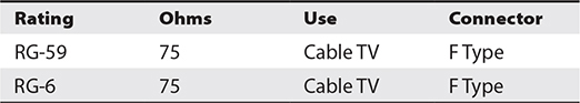
Table 2-1 Coaxial Cable
Twinaxial
Twinaxial cable is a type of coaxial cable that contains two central copper conductors wrapped around a single shield (Figure 2-16). You’ll see it used as a substitute for short fiber connections, generally between equipment within a rack, like switches. For such uses, it’s substantially cheaper than fiber and associated hardware. Twinaxial cable used this way is called a direct attached cable (DAC).

Figure 2-16 Twinaxial cable
Twisted Pair
The most common type of cabling used in networks consists of twisted pairs of cables, bundled together into a common jacket. Each pair in the cable works as a team either transmitting or receiving data. Using a pair of twisted wires rather than a single wire to send a signal reduces a specific type of interference, called crosstalk. The more twists per foot, the less crosstalk. Two types of twisted-pair cabling are manufactured: shielded and unshielded.
Shielded Twisted Pair Shielded twisted pair (STP) consists of twisted pairs of wires surrounded by shielding to protect them from EMI. There are six types, differentiated by which part gets shielding, such as the whole cable or individual pairs within the cable. Table 2-2 describes the six types. Figure 2-17 shows a typical piece of STP with the cladding partly removed so you can see the internal wiring.

Table 2-2 STP Standard

Figure 2-17 Shielded twisted pair
EXAM TIP You don’t need to memorize the STP variations for the CompTIA Network+ exam. You will, however, see them in the field once you become a network tech. The typical scenario in which you’d deploy STP rather than UTP is in high-EMI environments, where troubleshooting revealed that the unshielded cable couldn’t handle the noise.
Unshielded Twisted Pair Unshielded twisted pair (UTP) consists of twisted pairs of wires surrounded by a plastic jacket (Figure 2-18). This jacket does not provide any protection from EMI, just a slightly protective skin, so when installing UTP cabling, you must be careful to avoid interference from fluorescent lights, motors, and so forth. UTP costs much less than STP but, in most environments, performs just as well.
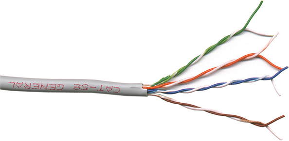
Figure 2-18 Unshielded twisted pair
Twisted-pair cabling has been around since the 1970s and evolving technologies demanded higher speeds. Over the years, manufacturers increased the number of twists per foot, used higher gauge cable, and added shielding to make twisted pair able to handle higher data speeds. To help network installers get the right cable for the right network technology, the cabling industry developed a variety of grades called category (Cat) ratings. Cat ratings are officially rated in megahertz (MHz), indicating the highest frequency the cable can handle. Table 2-3 shows the most common categories along with their status with the TIA (see the subsequent Note for more information).

Table 2-3 Cat Ratings for Twisted Pair
NOTE Several international groups set the standards for cabling and networking in general. Ready for alphabet soup? At or near the top is the International Organization for Standardization (ISO). The American National Standards Institute (ANSI) is both the official U.S. representative to ISO and a major international player. ANSI checks the standards and accredits other groups, such as the Telecommunications Industry Association (TIA).
UTP cables handle a certain frequency or cycles per second, such as 100 MHz or 1000 MHz. You could take the frequency number in the early days of networking and translate that into the maximum throughput for a cable. Each cycle per second (or hertz) basically accounted for one bit of data per second. A 10 million cycle per second (10 MHz) cable, for example, could handle 10 million bits per second (10 Mbps). The maximum amount of data that goes through the cable per second is called the bandwidth.
EXAM TIP The CompTIA Network+ exam is only interested in your knowledge of Cat 5, Cat 5e, Cat 6, Cat 6a, Cat 7, and Cat 8 cables. (In the field you’ll see category represented lowercase and uppercase, so Cat 6a or CAT 6a.)
For current networks, developers have implemented bandwidth-efficient encoding schemes, which means they can squeeze more bits into the same signal as long as the cable can handle it. Thus, the Cat 5e cable can handle a throughput of up to 1000 Mbps, even though it’s rated to handle a frequency of only up to 100 MHz.
Because most networks can run at speeds of up to 1000 Mbps, most new cabling installations use Category 6 (Cat 6) cabling, although a large number of installations use Cat 6a or Cat 7 to future-proof the network.
Make sure you can look at twisted pair and know its Cat rating. There are two places to look. First, twisted pair is typically sold in boxed reels, and the manufacturer will clearly mark the Cat level on the box (Figure 2-19). Second, look on the cable itself. The category level of a piece of cable is usually printed on the cable (Figure 2-20).
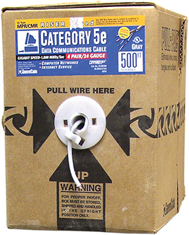
Figure 2-19 Cat level marked on box of twisted-pair cabling

Figure 2-20 Cat level on twisted-pair cabling
Try This!
The old landline telephones plugged in with a registered jack (RJ) connector. Telephones used RJ-11 connectors, designed to support up to two pairs of UTP wires. Current wired networks use the four-pair 8 position 8 contact (8P8C) connectors that most techs (erroneously) refer to as RJ-45 connectors (Figure 2-21). (There was an RJ45S connector used in telephones with slightly different keying. They look very similar to the 8P8C connectors, though, so speculation is that the name carried over from technicians installing that new UTP cabling.)

Figure 2-21 RJ-11 (left) and 8P8C/“RJ-45” (right) connectors
EXAM TIP CompTIA follows the common usage for networking cable connectors. You will not see 8P8C on the exam; you will only see RJ-45.
Fiber-Optic Cabling and Connectors
Fiber-optic cable transmits light rather than electricity, making it attractive for both high-EMI areas and long-distance transmissions. Whereas a single copper cable cannot carry data more than a few hundred meters at best, a single piece of fiber-optic cabling will operate, depending on the implementation, for distances of up to tens of kilometers. A fiber-optic cable has four components: the glass fiber itself (the core); the cladding, which is the part that makes the light reflect down the fiber; buffer material to give strength; and the insulating jacket (Figure 2-22).

Figure 2-22 Cross section of fiber-optic cabling
You might see the term fiber cables on the CompTIA Network+ exam to describe the two varieties of fiber-optic cables discussed in this section. Just as copper cables don’t have copper connectors, fiber cables don’t have fiber connectors, but that’s the term used in the CompTIA Network+ Spare Parts list. I’ll discuss cables and connector types shortly.
NOTE For those of you unfamiliar with it, the odd little u-shaped symbol describing fiber cable size (µ) stands for micro, or 1/1,000,000.
Fiber-optic cabling is manufactured with many different diameters of core and cladding. Cable manufacturers use a two-number designator to define fiber-optic cables according to their core and cladding measurements. Common fiber-optic cable sizes are 9/125 μm, 50/125 μm, and 62.5/125 μm. Almost all network technologies that use fiber-optic cable require pairs of fibers. One fiber is used for sending, the other for receiving. In response to the demand for two-pair cabling, manufacturers often connect two fibers together to create duplex fiber-optic cabling (Figure 2-23).

Figure 2-23 Duplex fiber-optic cable
Light can be sent down a fiber-optic cable as regular light or as laser light. The two types of light require totally different fiber-optic cables. Network technologies that use fiber optics use LEDs (light emitting diodes) to send light signals. A fiber-optic cable that uses LEDs is known as multimode fiber (MMF).
NOTE MMF can use a form of laser called a vertical-cavity surface-emitting laser (VCSEL), which differs substantially from the lasers used in SMF. You’ll find VCSELs in computer mice and laser printers, among other uses. And in case you’re curious, VCSELs are not on the CompTIA Network+ exam.
A fiber-optic cable that uses lasers is known as single-mode fiber (SMF). Using laser light and single-mode fiber-optic cables prevents a problem unique to multimode fiber optics called modal distortion (signals sent at the same time don’t arrive at the same time because the paths differ slightly in length) and enables a network to achieve phenomenally high transfer rates over incredibly long distances.
NOTE A nano—abbreviated as n—stands for 1/1,000,000,000, or one-billionth of whatever. Here you’ll see it as a nanometer (nm), one-billionth of a meter. That’s one tiny wavelength!
Fiber optics also defines the wavelength of light used, measured in nanometers (nm). Multimode cables transmit 850-nm or 1300-nm wavelengths, whereas single-mode transmits either 1310 nm or 1550 nm, depending on the laser.
NOTE The ANSI/TIA-568.3-D standard defines the nomenclature for fiber. The multimode standard prefix is OM (single-mode is OS). OM1 and OM2 are used in shorter runs with LEDs. OM3, OM4, and OM5 can use lasers and run at higher bandwidths, thus providing faster speed and greater distances. The ANSI/TIA 598-C standard provides guidelines for color-coding various fiber types. Single-mode fiber is yellow. OM1 and OM2 are both orange. OM3 and OM4 sport aqua, and OM5 appears in a spectacular lime green.
Fiber-optic cables come in a broad choice of connector types. There are over one hundred different connectors, but the four you need to know for the CompTIA Network+ exam are ST, SC, LC, and MT-RJ. Figure 2-24 shows the first three; Figure 2-25 shows an MT-RJ connector.

Figure 2-24 From left to right: ST, SC, and LC fiber-optic connectors

Figure 2-25 MT-RJ fiber-optic connector
Although all fiber connectors must be installed in pairs, the ST and SC connectors traditionally have unique ends. The LC and MT-RJ connectors are always duplex, meaning both the send and receive cables are attached. You can certainly find SC connectors or sleeves to make them duplex too, so don’t get too caught up with which can be which. We’ll revisit fiber-optic connectors in Chapter 4 when we discuss implementation of specific networking standards.
NOTE Most technicians call common fiber-optic connectors by their initials—such as ST, SC, or LC—perhaps because there’s no consensus about what words go with those initials. ST probably stands for straight tip, although some call it snap and twist. But SC and LC? How about subscriber connector, standard connector, or Siemon connector for the former, and local connector or Lucent connector for the latter? If you want to remember the connectors for the exam, try these: snap and twist for the bayonet-style ST connectors; stick and click for the straight push-in SC connectors; and little connector for the … little … LC connector.
Fire Ratings
Did you ever see the movie The Towering Inferno? Don’t worry if you missed it—The Towering Inferno was one of the better disaster movies of the 1970s, although it was no Airplane! Anyway, Steve McQueen stars as the fireman who saves the day when a skyscraper goes up in flames because of poor-quality electrical cabling. The burning insulation on the wires ultimately spreads the fire to every part of the building. Although no cables made today contain truly flammable insulation, the insulation is made from plastic, and if you get any plastic hot enough, it will create smoke and noxious fumes. The risk of burning insulation isn’t fire—it’s smoke and fumes.
To reduce the risk of your network cables burning and creating noxious fumes and smoke, Underwriters Laboratories and the National Electrical Code (NEC) joined forces to develop cabling fire ratings. The two most common fire ratings are PVC and plenum. Cable with a polyvinyl chloride (PVC) rating has no significant fire protection. If you burn a PVC-rated cable, it creates lots of smoke and noxious fumes. Burning plenum-rated cable creates much less smoke and fumes, but plenum-rated cable costs about three to five times as much as PVC-rated cable. Most city ordinances require the use of plenum cable for network installations. The bottom line in such scenarios? Get plenum!
The space between the acoustical tile ceiling in an office building and the actual concrete ceiling above is called the plenum—hence the name for the proper fire rating of cabling to use in that space. A third type of fire rating, known as riser, designates the proper cabling to use for vertical runs between floors of a building. Riser-rated cable provides less protection than plenum cable, though, so most installations today use plenum for runs between floors.
EXAM TIP Look for a troubleshooting scenario question on the CompTIA Network+ exam that asks you to compare plenum versus PVC cable best use. If it goes in the wall, make it plenum!
Networking Industry Standards—IEEE
The Institute of Electrical and Electronics Engineers (IEEE) defines industry-wide standards that promote the use and implementation of technology. In February 1980, a committee called the 802 Working Group took over from the private sector the job of defining network standards. The IEEE 802 committee defines frames, speeds, distances, and types of cabling to use in a network environment. Concentrating on cables, the IEEE recognizes that no single cabling solution can work in all situations and, therefore, provides a variety of cabling standards.
IEEE committees define standards for a wide variety of electronics. The names of these committees are often used to refer to the standards they publish. The IEEE 1284 committee, for example, set standards for parallel communication, so you would see parallel cables marked “IEEE 1284 compliant,” as in Figure 2-26.

Figure 2-26 Parallel cable marked IEEE 1284 compliant
The IEEE 802 committee sets the standards for networking. Although the original plan was to define a single, universal standard for networking, it quickly became apparent that no single solution would work for all needs. The 802 committee split into smaller subcommittees, with names such as IEEE 802.3 and IEEE 802.11. Table 2.4 shows the currently recognized IEEE 802 subcommittees and their areas of jurisdiction. The missing numbers, such as 802.2 and 802.12, were used for committees long-ago disbanded. Each subcommittee is officially called a Working Group, except the few listed as a Technical Advisory Group (TAG) in the table.

Table 2-4 Some IEEE 802 Subcommittees
Chapter Review
Questions
1. Which of the following topologies required termination?
A. Star
B. Bus
C. Mesh
D. Ring
2. Star-bus is an example of a _______________ topology.
A. transitional
B. system
C. hybrid
D. rampant
3. Of the topologies listed, which one is the most fault-tolerant?
A. Point-to-point
B. Bus
C. Star
D. Ring
4. What term is used to describe the interconnectivity of network components?
A. Segmentation
B. Map
C. Topology
D. Protocol
5. Coaxial cables all have a(n) _______________ rating.
A. resistance
B. watt
C. speed
D. Ohm
6. Which of the following is a type of coaxial cable?
A. RJ-45
B. RG-6
C. BNC
D. Barrel
7. Which network topology connected nodes with a ring of cable?
A. Star
B. Bus
C. Ring
D. Mesh
8. Which network topology is most commonly seen only in wireless networks?
A. Star
B. Bus
C. Ring
D. Mesh
9. Which of the following is a duplex fiber-optic connection?
A. LC
B. RJ-45
C. ST
D. SC
10. What is the most common category of UTP used in new cabling installations?
A. Cat 3
B. Cat 5e
C. Cat 6
D. Cat 7
Answers
1. B. In a bus topology, all computers connected to the network via a main line. The cable had to be terminated at both ends to prevent signal reflection.
2. C. Star-bus is a hybrid topology because it uses a star physical topology and a bus signal topology.
3. C. Of the choices listed, only star topology has any fault tolerance.
4. C. Topology is the term used to describe the interconnectivity of network components.
5. D. All coaxial cables have an Ohm rating. RG-59 and RG-6 both are rated at 75 Ohms.
6. B. RG-6 is a type of coaxial cable.
7. C. The aptly named ring topology connected nodes with a central ring of cable.
8. D. Mesh is, for the most part, unique to wireless networks.
9. A. Of the options given, only the LC connector is designed for duplex fiber-optic.
10. C. Cat 6 is the most common cabling category installed today, although Cat 6a and Cat 7 are gaining in popularity.