CHAPTER 13
WAN Connectivity
The CompTIA Network+ certification exam expects you to know how to
• 1.2 Explain the characteristics of network topologies and network types
• 1.3 Summarize the types of cables and connectors and explain which is the appropriate type for a solution
• 1.5 Explain common ports and protocols, their application, and encrypted alternatives
• 2.1 Compare and contrast various devices, their features, and their appropriate placement on the network
• 2.4 Given a scenario, install and configure the appropriate wireless standards and technologies
• 4.4 Compare and contrast remote access methods and security implications
To achieve these goals, you must be able to
• Describe WAN telephony technologies
• Compare last-mile connections for connecting homes and businesses to the Internet
• Discuss and implement various remote access connection methods
• Troubleshoot various WAN scenarios
Computers connect to other computers locally in a local area network (LAN)—you’ve read about LAN connections throughout this book—and remotely through a number of different methods. Interconnecting computers over distances, especially when the connections cross borders or jurisdictions, creates a wide area network (WAN), though the term is pretty flexible. For example, you can refer to a campus area network (CAN)—a bunch of interconnected LANs on a campus—as a WAN.
Remote connections have been around for a long time. Before the Internet, network users and developers created ways to take a single system or network and connect it to another faraway system or network. This wasn’t the Internet! These were private interconnections of private networks. These connections were very expensive and, compared to today’s options, pretty slow. As the Internet and WAN connectivity developed, most of the same technologies used to make the earlier private remote connections became the way the Internet itself interconnects.
This chapter first explores the technologies that enable WAN connections. The second portion examines the last-mile technologies that enable users and organizations to tap into both private WANs and the Internet. The third section explores the use of WAN technology to tap directly into a remote LAN through virtual private networking. The chapter wraps up with a discussion on troubleshooting WAN technologies.
Historical/Conceptual
WAN Technologies
We’ve discussed briefly the Tier 1 routers and ISPs of the Internet in Chapter 12 briefly, but let’s look at them here more closely. Those of us in the instruction business invariably start this description by drawing a picture of the United States and then adding lines connecting big cities, as shown in Figure 13-1.

Figure 13-1 The Tier 1 Internet
But what are these lines and where did they come from? If the Internet is just a big TCP/IP network, wouldn’t these lines be Ethernet connections? Maybe copper, maybe fiber, but surely they’re Ethernet? Well, traditionally they’re not. Many of the long-distance connections that make up the Internet use a unique type of signal called SONET. SONET was originally designed to handle special heavy-duty circuits with names like T1.
Technologies that connect the servers that form the backbone of the Internet—and private WAN networks—have evolved over the years, from standards created for telephony to current high-end Ethernet. And a lot of these standards coexist. This section explores the public and private WAN connections, from the fading SONET/SDH standards to more recent 100 Gigabit Ethernet (100GbE) and 400 Gigabit Ethernet (400GbE), and the private WAN connections featuring MPLS and SD-WAN.
SONET
By 1987, the primary fiber-optic cable carriers settled on a single international standard called Synchronous Optical Network (SONET) in the United States and Synchronous Digital Hierarchy (SDH) in Europe for handling the interconnections of long-distance Internet routers.

NOTE Students often wonder why two separate names exist for the same technology. In reality, SONET and SDH vary a little in their signaling and frame type, but routers and other magic boxes on the Internet handle the interoperability between the standards. The American National Standards Institute (ANSI) publishes the standard as SONET; the International Telecommunication Union (ITU) publishes the standard as SDH, but includes SONET signaling. For simplicity’s sake, and because SONET is the more common term in the United States, this book uses SONET as the term for this technology.
All of these carriers adopting the same standard created simple interconnections between competing voice and data carriers. This adoption defined the moment that truly made the Internet a universal network. Before SONET, interconnections happened, but they were outlandishly expensive, preventing the Internet from reaching many areas of the world.
SONET remains an important standard for long-distance, high-speed, fiber-optic transmission systems. SONET defines interface standards at the Physical and Data Link layers of the OSI seven-layer model. The physical aspect of SONET is partially covered by the Optical Carrier standards, but it also defines a ring-based topology that most SONET adopters use. SONET does not require a ring, but a SONET ring has fault tolerance in case of line loss. As a result, many of the big long-distance optical pipes for the world’s telecommunications networks are SONET rings.
The Optical Carrier (OC) standards denote the optical data-carrying capacity (in bits per second) of fiber-optic cables in networks conforming to the SONET standard. The OC standards describe an escalating series of speeds, designed to meet the needs of medium-to-large corporations. SONET establishes OC speeds from 51.8 Mbps (OC-1) to 39.8 Gbps (OC-768).
Test Specific
Fiber Improvements
Still want more throughput? Many fiber devices use a very clever feature called bidirectional wavelength division multiplexing (WDM or BWDM) or its newer and more popular version, dense wavelength division multiplexing (DWDM). DWDM enables an individual single-mode fiber to carry multiple signals by giving each signal a different wavelength (using different colors of laser light). The result varies, but a single DWDM fiber can support ~150 signals, enabling, for example, a 51.8-Mbps OC-1 line to run at 51.8 Mbps × 150 signals = 7.6 gigabits per second! DWDM has been very popular for long-distance lines as it’s usually less expensive to replace older SONET/OC-x equipment with DWDM than it is to add more fiber lines.
NOTE DWDM isn’t just upgrading SONET lines; DWDM works just as well on long-distance fiber Ethernet.
A related technology, coarse wavelength division multiplexing (CWDM), also relies on multiple wavelengths of light to carry a fast signal over long distances. It’s simpler than DWDM, which limits the practical distances of CWDM to a mere 60 km. You’ll see it used in higher-end LANs with 10GBASE-LX4 networks, for example, where its lower cost (compared to direct competitors) offers benefits.
In the mid-life of the Internet, backbone runs were largely composed of SONET links. Today, SONET has mostly been replaced with a mix of ever-improving optical links such as 100 Gigabit Ethernet, 400 Gigabit Ethernet, and others.
Private WANs
Many organizations connect far-flung network resources through private connections rather than across the Internet. The purchase of dedicated connections—leased lines—from telecommunication companies enables these organizations to secure network communication with no fear of hackers accessing network resources. These dedicated connections are expensive, as you might imagine, but ideal for many businesses. Several technologies provide the underpinnings for private WANs: MPLS, SD-WAN, and metro Ethernet.
MPLS
In an IP network, a router receives an incoming IP packet, checks the destination IP address, consults its routing table, and then forwards the packet to the next hop. Nothing in the IP packet tells the router details about how to get to that destination. This router-intensive analysis of where to send each packet happens at every hop that packet takes from its source to its destination. This works great for a typical IP network, but years ago applications like video conferencing suffered over distances. (This has changed a lot today, but go with me here on the motivation for something better.)
In a private network of dedicated leased lines, a few destinations can use a different switching technology to make direct or more efficient connections. Multiprotocol Label Switching (MPLS) provides a platform-agnostic labeling system to greatly improve performance compared to an IP network.
MPLS adds an MPLS label that sits between the Layer 2 header and the Layer 3 header. Layer 3 is always IP, so MPLS labels sit between Layer 2 and the IP headers. Figure 13-2 shows the structure of an MPLS header.

Figure 13-2 MPLS header
The MPLS header consists of four parts:
• Label A unique identifier, used by MPLS-capable routers to determine how to move data.
• Experimental Bits (Exp) A relative value used to determine the importance of the labeled packet to be able to prioritize some packets over others.
• Bottom of Label Stack (S) In certain situations, a single packet may have multiple MPLS labels. This single bit value is set to 1 for the initial label.
• Time to Live (TTL) A value that determines the number of hops the label can make before it’s eliminated
Figure 13-3 shows the location of the MPLS header.

Figure 13-3 MPLS header inserted in a frame
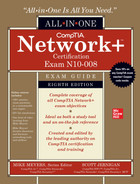
The original idea for MPLS was to give individual ISPs a way to move traffic through their morass of different interconnections and switches more quickly and efficiently by providing network-wide quality of service (QoS). MPLS-capable routers avoid running IP packets through their full routing tables and instead use the header information to route packets quickly. Where “regular” routers use QoS on an individual basis, MPLS routers use their existing dynamic routing protocols to send each other messages about their overhead, enabling QoS to span an entire group of routers (Figure 13-4).
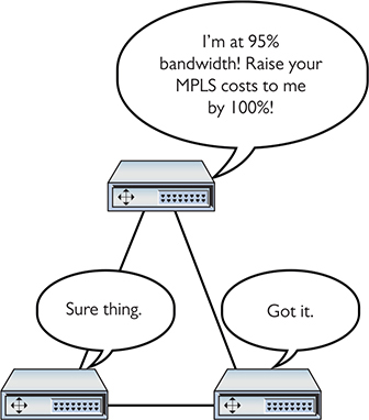
Figure 13-4 MPLS routers talk to each other about their overhead.
Let’s see how the MPLS-labeled packets, combined with MPLS-capable routers, create improved throughput. To see this happen, I need to introduce a few MPLS terms:
• Forwarding Equivalence Class (FEC) FEC is a set of packets that can be sent to the same place, such as a single broadcast domain of computers connected to a router.
• Label switching router (LSR) An LSR looks for and forwards packets based on their MPLS label. These are the “MPLS routers” mentioned previously.
• Label edge router (LER) An LER is an MPLS router that has the job of adding MPLS labels to incoming packets that do not yet have a label, and stripping labels off outgoing packets.
• Label Distribution Protocol (LDP) LSRs and LERs use LDP to communicate dynamic information about their state.
Figure 13-5 shows a highly simplified MPLS network. Note the position of the LERs and LSRs.

Figure 13-5 Sample MPLS network
When an MPLS network comes online, administrators configure initial routing information, primarily setting metrics to routes (Figure 13-6).
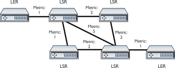
Figure 13-6 MPLS initial routes added
LERs have the real power in determining routes. Because LERs are the entrances and exits for an MPLS network, they talk to each other to determine the best possible routes. As data moves from one FEC, the LERs add an MPLS label to every packet. LSRs strip away incoming labels and add their own. This progresses until the packets exit out the opposing LER (Figure 13-7).

Figure 13-7 Data routing through an MPLS network
SD-WAN
One interesting use of MPLS networks is to provide Internet connectivity to a back office or satellite location via a public-facing router at the telephone company’s central office, a backhaul connection. This keeps the full security in place (the good part about MPLS and private WANs), but the connection will most likely be slow compared to a direct Internet connection.
Another disadvantage of MPLS is that acquiring and installing dedicated connections between the central office and the various back offices or satellites is expensive. The public Internet eclipsed any performance advantage of dedicated networks, so the only thing superior in the latter is security.
Software-defined wide area networking (SD-WAN) enables traffic over the Internet that incorporates a lot of the features of MPLS, with efficient addressing and routing for a lot of traffic. SD-WAN maintains high security as well. SD-WAN relies on virtualization technologies covered more fully in Chapter 15. (Note also that the Network+ exam objectives drop the hyphen, so SDWAN.)
Metro Ethernet
A metro Ethernet network creates a secure, private network within a city using fiber-optic cabling and Ethernet technology. CompTIA refers to this networking technology as metro-optical. The metropolitan area network (MAN) created does not use the Internet to connect and thus doesn’t require security. Use of Ethernet reduces the cost of implementing a metro Ethernet network substantially compared to an MPLS or SD-WAN network.
NOTE A metro Ethernet network can connect offices and individuals and provide Internet connectivity.
Last-Mile Technologies
Various technologies enable individuals and organizations to tap into wide area networks, such as the Internet. These technologies enable connections to ISPs, businesses that lease direct connections and in turn provide a public onramp—provider links—to the Internet. This section explores DSL, cable, fiber [to the premises], satellite, and cellular, the connections most frequently termed the last mile—literally the connection options from a telco central office to the premises.
DSL
Many telephone companies offer a digital subscriber line (DSL) connection, a fully digital, dedicated (no phone number) connection. DSL represented the next great leap forward past Integrated Services Digital Network (ISDN) for telephone lines. A physical DSL connection manifests as just another Public Switched Telephone Network (PSTN) connection, using the same telephone lines and RJ-11 jacks as any regular phone line. DSL comes in a number of versions, but the two most important to know for the fundamental technologies are symmetric DSL (SDSL) and asymmetric DSL (ADSL).
NOTE AT&T (along with other telecoms) uses a very fast DSL version in some of its Internet offerings called very-high-bit-rate DSL (VDSL). The current version, VDSL2, can provide simultaneous upload and download speeds in excess of 100 Mbps, though only at short distances (~300 meters). Typical speeds using this technology are a lot slower, in the range of 8 to 16 Mbps down and 1 to 2 Mbps up.
SDSL
SDSL provides equal upload and download speeds and, in theory, provides speeds up to 15 Mbps, although the vast majority of ISPs provide packages ranging from 192 Kbps to 9 Mbps.
ADSL
ADSL uses different upload and download speeds. ADSL download speeds are much faster than the upload speeds. Most small office and home office (SOHO) users are primarily concerned with fast downloads for things like Web pages and can tolerate slower upload speeds. ADSL provides theoretical maximum download speeds up to 15 Mbps and upload speeds up to 1 Mbps. Real-world ADSL download speeds vary from 384 Kbps to 15 Mbps, and upload speeds go from as low as 128 Kbps to around 768 Kbps. ADSL is less expensive than SDSL.
Try This!
DSL Features
One nice aspect of DSL is that you don’t have to run new phone lines. The same DSL lines you use for data can simultaneously transmit your voice calls.
All versions of DSL have the same central office–to–end user distance restrictions as ISDN—around 18,000 feet from your demarc to the central office. At the central office, your DSL provider has a device called a DSL Access Multiplexer (DSLAM) that connects multiple customers to the Internet.
The DSL modem in your house is considered a termination point, a demarc. Any DSL modem today is a smart jack, a network interface unit (NIU) that enables loopback testing so the ISP can remotely check your line and box.
Installing DSL
DSL operates using your preexisting telephone lines (assuming they are up to specification). This is wonderful but also presents a technical challenge. For DSL and your run-of-the-mill plain old telephone service (POTS) line to coexist, you need to filter out the DSL signal on the POTS line. A DSL line has three information channels: a high-speed downstream channel, a medium-speed duplex channel, and a POTS channel.
NOTE If you install a telephone onto a line in your home with DSL and you forget to add a filter, don’t panic. You won’t destroy anything, though you won’t get a dial tone either! Just insert a DSL POTS filter and the telephone will work.
Segregating the two DSL channels from the POTS channel guarantees that your POTS line will continue to operate even if the DSL fails. You accomplish this by inserting a filter on each POTS line, or a splitter mechanism that allows all three channels to flow to the DSL modem but sends only the POTS channel down the POTS line. The DSL company should provide you with a few POTS filters for your telephones. If you need more, most computer/electronics stores stock DSL POTS filters.
A common early DSL installation consisted of a DSL modem connected to a telephone wall jack and to a standard network interface card (NIC) in your computer (Figure 13-8). The DSL line ran into a DSL modem via a standard phone line with RJ-11 connectors. Today you’d add a router in between the DSL modem and the wall jack.
Figure 13-8 A DSL modem connection between a PC and telco
The DSL modem connects to the gateway router with a Cat 5/6 patch cable, which, in turn, connects to the company’s switch. Figure 13-9 shows an ADSL modem and a router.

Figure 13-9 DSL connection
The first generation of DSL providers used a bridged connection; once the DSL line was running, it was as if you had snapped an Ethernet cable into your NIC. You were on the network. Those were good days for DSL. You just plugged your DSL modem into your NIC and, assuming your IP settings were whatever the DSL folks told you to use, you were running.
The DSL providers didn’t like that too much. There was no control—no way to monitor who was using the DSL modem. As a result, the DSL folks started to use Point-to-Point Protocol over Ethernet (PPPoE), a protocol that was originally designed to encapsulate PPP frames into Ethernet frames. The DSL people adopted it to make stronger controls over your DSL connection. In particular, you could no longer simply connect; you now had to log on with an account and a password to make the DSL connection. PPPoE is now predominant on DSL. If you get a DSL line, your operating system has software to enable you to log onto your DSL network. Most small office/home office (SOHO) routers come with built-in PPPoE support, enabling you to enter your username and password into the router itself (Figure 13-10).

Figure 13-10 PPPoE settings in SOHO router
Broadband Cable
The first big competition for ADSL came from the cable companies. A majority of houses in America have a coax cable for cable TV. In a moment of genius, the cable industry realized that if it could put the Home Shopping Network and the History Channel into every home, why not provide Internet access? The entire infrastructure of the cabling industry had to undergo some major changes to deal with issues like bidirectional communication, but cable modem service quickly became common in the United States. Cable modems are now as common as cable TV boxes.
Cable modems have the impressive benefit of phenomenal top speeds. These speeds vary from cable company to cable company, but most advertise speeds in the 5 Mbps to 1.2 Gbps range. Many cable modems provide a throughput speed of 30 Mbps to 1.2 Gbps for downloading and 5 Mbps to 35 Mbps for uploading—there is tremendous variance among different providers.
In a cable modem installation, the cable modem connects to an outlet via a coaxial cable. It’s separate from the one that goes to the television. It’s the same cable line, just split from the main line as if you were adding a second cable outlet for another television. A cable modem connects to a router, which in turn connects to a PC using a standard NIC and UTP cabling (Figure 13-11).

Figure 13-11 Cable modem
Cable modems connect using coax cable to a headend, similar to a telephone company’s central office. Headends, in turn, connect to the cable company’s network. This network uses a unique protocol called Data Over Cable Service Interface Specification (DOCSIS). The current specification is DOCSIS 4.0.
You’ll have a hard time telling a cable modem from a DSL modem. The only difference, other than the fact that one will have “cable modem” printed on it whereas the other will say “DSL modem,” is that the cable modem has a coax F connector and an RJ-45 connector; the DSL modem has an RJ-11 connector and an RJ-45 connector.
Cable companies aggressively market high-speed packages to business customers, making cable a viable option for businesses.
Satellite
Living in the countryside may have its charms, but you’ll have a hard time getting high-speed Internet out on the farm. For those too far away to get anything else, satellite may be your only option. Satellite access comes in two types: one-way and two-way. One-way means that you download via satellite, but you must use a PSTN/dial-up modem connection for uploads. Two-way means the satellite service handles both the uploading and downloading.
NOTE Companies that design satellite communications equipment haven’t given up on their technology. The standard HughesNet products advertise download speeds up to 25 Mbps. The SpaceX Starlink service claims potential download speeds of 1 Gbps worldwide, though it’s still in beta as I type.
Satellite requires a small satellite antenna, identical to the ones used for satellite television. This antenna connects to a satellite modem, which, in turn, connects to your PC or your network (Figure 13-12).

Figure 13-12 Satellite connection

TIP Neither cable modems nor satellites use PPP, PPPoE, or anything else that begins with three Ps.
Fiber
DSL was the first popular last-mile WAN option, but over the years cable modems have taken the lead. In an attempt to regain market share, telephone providers rolled out fiber-to-the-home/fiber-to-the-premises options that have changed the game in many cities In the United States, two companies, AT&T and Verizon (Fios), offer Internet connectivity, television, and phone services at super speeds, such as bidirectional 1-Gbps throughput. Some markets also have Internet-only fiber offerings, such as Google Fiber, where users connect at 1 Gbps.
To make rollouts affordable, most fiber-to-the-home technologies employ a version of passive optical network (PON) architecture that uses a single fiber to the neighborhood switch and then individual fiber runs to each final destination. PON uses WDM to enable multiple signals to travel on the same fiber and then passively splits the signal at the switch to send traffic to its proper recipient.
NOTE Most municipalities in the United States have very tight deals in place with telephone and cable companies, allowing little room for any other high-speed Internet service. A few cities have bucked the regional monopolies and done pretty well, such as Chattanooga, Tennessee. Their publicly owned electric utility—EPB—rolled out fiber to every home and business by 2011 and currently offers Internet speeds up to 10 Gbps.
Cellular WAN
Anyone with a smartphone these days can enjoy the convenience of using wireless cellular technology. Who doesn’t love firing up an Android phone or an iPhone and cruising the Internet from anywhere? As cell-phone technology converges with Internet access technologies, competent techs need to understand what’s happening behind the scenes. That means tackling an alphabet soup of standards.
Regardless of the standard, the voice and data used on smartphones (unless you have 802.11 wireless turned on) moves through a cellular wireless network with towers that cover the world (Figure 13-13).

Figure 13-13 Cellular tower
Mobile data services started in the mid-1980s and, as you might imagine, have gone through a dizzying number of standards and protocols, all of which have been revised, improved, abandoned, and reworked. Instead of trying to advertise these fairly complex and intimidating technologies, the industry instead came up with the marketing term generations, abbreviated by a number followed by the letter G: 2G, 3G, 4G, and 5G.
Salespeople and TV commercials use these terms to push mobile cellular services. The generation terms aren’t generally used within the industry, and certainly not at a deeply technical level. As I go through the standards that you’ll see on the exam and encounter in real life, I’ll mention both the technical name and the generation where applicable. I’ll cover six common terms here:
• GSM and EDGE
• CDMA
• HSPA+
• LTE
• 5G
GSM and EDGE
The Global System for Mobile Communications (GSM), the first group of networking technologies widely applied to mobile devices, relied on a type of time-division multiplexing called time-division multiple access (TDMA). TDMA enabled multiple users to share the same channel more or less at the same time; and in this scenario, the switching from one user to another happened so quickly no one noticed.
NOTE There’s no “C” on the end of GSM because it originally came from a French term, Groupe Spécial Mobile.
GSM introduced the handy subscriber identity module (SIM) card that is now ubiquitous in smartphones (Figure 13-14). The SIM card identifies the phone, enabling access to the cellular networks, and stores some other information (contents differ according to many factors, none relevant for this discussion).

Figure 13-14 Original SIM card
The GSM standard was considered a 2G technology. The standard continued to improve over the years, getting new names and better data speeds. One of the last of these was Enhanced Data rates for GSM Evolution (EDGE), which offered data speeds up to 384 Kbps.
CDMA
Code-division multiple access (CDMA) came out not long after GSM, but used a spread-spectrum form of transmission that was totally incompatible with GSM’s TDMA. Rather than enabling multiple users to share a single channel by splitting the channel into time slices, spread-spectrum transmission changed the frequencies used by each user.
CDMA was considered superior to GSM, and U.S. carriers adopted CDMA en masse, which created some problems later since the rest of the world went with GSM. Plus, CDMA lacked some key features, such as SIM cards.
NOTE The original CDMA was considered a 2G technology.
HSPA+
In the late 1990s the International Telecommunication Union (ITU) forwarded a standard called International Mobile Telecommunications-2000 (IMT-2000) to address shortcomings in mobile technology. IMT-2000 defined higher speeds, support for full-time Internet connections, and other critical functions. The standard pushed support for multimedia messaging system (MMS) (so you can send cat pictures in your text messages) and IP-based telephony.
Both GSM and CDMA improved during the late 1990s to the mid-2000s to address IMT-2000: all these improvements were marketed under probably the most confusing marketing term ever used: 3G. Ideally, 3G meant a technology that supported IMT-2000, although the industry was very lax in how companies used this term. (This time period is so confusing that many technologies in this period were given decimal generations to clarify the situation. One example is GSM EDGE being called 2.9G due to its lack of full IMT-2000 support.)
Evolved High-Speed Packet Access (HSPA+) was the final 3G data standard, providing theoretical speeds up to 168 Mbps, although most HSPA+ implementations rarely exceeded 10 Mbps.
LTE
Devices and networks using Long Term Evolution (LTE) technology rolled out world-wide in the early 2010s and now dominate wireless services. Marketed as and now generally accepted as a true 4G technology, LTE networks feature speeds of up to 300 Mbps download and 75 Mbps upload. All LTE services use SIM cards such as the one shown in Figure 13-15. Note the SIM size in Figure 13-15 compared to the much older SIM in Figure 13-14. The much smaller SIM in Figure 13-15 is a nano-SIM. The SIM in Figure 13-14 is an original, standard SIM.

Figure 13-15 Modern nano-SIM
Smartphones have LTE radios built in, but it’s easy to add LTE to almost any device. Need LTE on a laptop or a desktop? No problem, get an LTE NIC and just plug it into a convenient USB port (Figure 13-16).

Figure 13-16 Cellular wireless NIC on USB stick
5G
The successor to 4G, called 5G (for fifth generation), offers substantially upgraded technology and dramatically increased speeds over its predecessor. Cellular companies started rolling out 5G in 2019.
5G operates at three bands, low, medium, and high. Clever, huh? All three use a range of frequencies, with low-band running 600–800 MHz (similar to 4G), medium-band at 2.5–3.7 GHz, and high-band at 25–39 GHz. The higher the frequency, the faster the possible throughput speeds and the shorter the range. Depending on the radios installed and the radios in the portable devices that use 5G, the expected speed ranges are 30 Mbps up to 1 Gbps.
The high-band 5G implementation will require dense saturation of transmitters/receivers and antennas, so will work best in dense settings, such as stadiums. Additionally, the exceptional speeds offered by 5G makes the technology a viable replacement for other technologies for mobile devices such as laptops and tablets, as well as smoking-fast speeds in the latest smartphones.
Which Connection?
With so many connection options for homes and small offices, making a decision is often a challenge. Your first question is availability: Which services are available in your area? The second question is, how much bandwidth do you need? The latter is a question of great debate. Most services are more than happy to increase service levels if you find that a certain level is too slow. I usually advise clients to start with a relatively slow level and then increase if necessary. After all, once you’ve tasted the higher speeds, going slower is hard, but the transition to faster is relatively painless!
Try This!
Remote Access
Because most businesses are no longer limited to a simple little shop like you would find in a Dickens novel, many people need to be able to access files and resources over a great distance. Enter remote access. Remote access uses WAN and LAN connections to enable a computer user to log onto a network from the other side of a city, a state, or even the globe. As people travel, information has to remain accessible. Remote access enables users to connect a server at the business location and log into the network as if they were in the same building as the company. The only problem with remote access is that there are so many ways to do it! This section covers two of the most common forms, remote terminal and virtual private networking.
NOTE You’ll see the term extranet more in books than in the day-to-day workings of networks and network techs. So what is an extranet? Whenever you allow authorized remote users to access some part of your private network, you have created an extranet.
Remote Terminal
You can use a terminal emulation program to create a remote terminal, a connection on a faraway computer that enables you to control that computer as if you were sitting in front of it, logged in. Terminal emulation has been a part of TCP/IP from its earliest days, in the form of good-old Telnet. Because it dates from pre-GUI days, Telnet is a text-based utility; most modern operating systems are graphical, so there was a strong desire to come up with graphical remote terminal tools. Citrix Corporation made the first popular terminal emulation products—the WinFrame/MetaFrame products (Figure 13-17). (Their current product is called Citrix Virtual Apps and Desktop.)

Figure 13-17 Citrix MetaFrame
NOTE From a security standpoint, all remote connections have authentication and authorization considerations. Connecting via Telnet, as you’ll recall from Chapter 8, can require a username and password for authentication, but it lacks any real security because credentials are passed unencrypted. Most other remote connection types at least have encryption to make the authentication part more secure. Once logged into a remote system, the remote operating system handles authorization.
Remote terminal programs all require a server and a client. The server is the computer to be controlled. The client is the computer from which you do the controlling. Citrix created a standard called Independent Computing Architecture (ICA) that defined how terminal information was passed between the server and the client. Citrix made a breakthrough product—so powerful that Microsoft licensed the Citrix code and created its own product called Windows Terminal Services. Not wanting to pay Citrix any more money, Microsoft then created its own standard called Remote Desktop Protocol (RDP) and unveiled a new remote terminal called Remote Desktop Connection (RDC) starting with Windows XP (so it’s been around a long time). Figure 13-18 shows Windows Remote Desktop Connection running on a Windows 10 system, connecting to a Windows Server.

Figure 13-18 RDC in action
NOTE All RDP applications run on port 3389 by default.
Current versions of Windows Server can provide a secure tunnel via HTTPS for an RDC session. The server runs the Remote Desktop Gateway (RDG) component or role to supply security with TLS.
A number of third parties make absolutely amazing terminal emulation programs that run on any operating system. The best of these, VNC (VNC stands for Virtual Network Computing), doesn’t let you share folders or printers because it is only a terminal emulator (Figure 13-19), but it runs on every operating system, is solid as a rock, and even runs from a Web browser. It works nicely in Secure Shell (SSH) tunnels for great security, plus it comes, by default, with every copy of macOS and almost every Linux distro. Why bother sharing if you can literally be at the screen? Oh, and did I mention that VNC is completely free?

Figure 13-19 VNC in action
NOTE VNC and SSH enable in-band management of resources, meaning software installed on both the client and the remote system enables direct control over resources. The interaction uses the primary network connection for both devices, thus it’s in-band and sharing resources (and traffic) with the regular network.
In-band management is fast and inexpensive but has a couple of drawbacks in a busy network. First, the remote system must be booted up with its operating system fully loaded for this to work. Second, putting management of a remote system on the main network doesn’t provide as much security or control as a dedicated, alternative connection would provide.
Many servers employ lights-out-management (LOM) capabilities that enable out-of-band management to address these issues. We’ll see a lot more of these technologies when we discuss network monitoring and management in Chapter 20.
Virtual Private Networks
Remote connections have been around for a long time, even before the Internet existed. The biggest drawback to remote connections was the cost to connect. If you were on one side of the continent and had to connect to your LAN on the other side of the continent, the only connection option was a telephone. Or, if you needed to connect two LANs across the continent, you ended up paying outrageous monthly charges for a private connection. The introduction of the Internet gave people wishing to connect to their home or work networks a very inexpensive connection option, but there was one problem—the whole Internet was (and is) open to the public. People wanted to stop using dial-up and expensive private connections and use the Internet instead, but they wanted to be able to do it securely.
If you read the previous chapter, you might think you could use some of the tools for securing TCP/IP to help, and you would be correct. Several standards use encrypted tunnels between a computer or a remote network and a private network through the Internet (Figure 13-20), resulting in what is called a virtual private network (VPN).

Figure 13-20 VPN connecting computers across the United States
An encrypted tunnel requires endpoints—the ends of the tunnel where the data is encrypted and decrypted. In the tunnels you’ve seen thus far, the client for the application sits on one end and the server sits on the other. VPNs do the same thing. Either some software running on a computer or, in some cases, a dedicated box must act as an endpoint for a VPN (Figure 13-21).
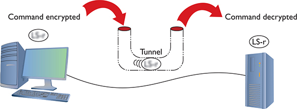
Figure 13-21 Typical tunnel
The key with the VPN is that the computers should be on the same network—and that means they must all have the same network ID. You would want the laptop that you use in the Denver airport lounge, for example, to have the same network ID as the computers in the LAN back at the office. But there’s no simple way to do this. If it’s a single client trying to access a network, that client is going to take on the IP address from its local DHCP server. In the case of your laptop in the airport, your network ID and IP address come from the DHCP server in the airport, not the DHCP server back at the office.
To make the VPN work, you need VPN client software installed on your local machine—the laptop at the Denver airport—and VPN server software or hardware at your office. You connect your laptop first to the Internet using the airport wireless network; it’s just a normal Internet connection. Second, the VPN client software creates a virtual NIC on your laptop (endpoint 1), makes a connection with the VPN server at the office (endpoint 2), and then, in essence, creates a virtual direct cable from the virtual NIC to the office (Figure 13-22). That “virtual cable” is called a VPN tunnel. The laptop now has two IPv4 addresses. One is local from the airport DHCP server. The other is “local,” but works with the office network. That second IP address goes with the virtual NIC.

Figure 13-22 Endpoints must have their own IP addresses.
Clever network engineers have come up with many ways to make this work, and those implementations function at different layers of the OSI model. PPTP and L2TP, for example, work at the Data Link layer. Many VPNs use IPsec at the Network layer to handle encryption needs. TLS VPNs don’t really fit into the OSI model well at all, with some features in the Session layer and others in the Presentation layer.
PPTP VPNs
So how do you make IP addresses appear out of thin air? Point-to-Point Protocol (PPP) can make the connection.
Microsoft got the ball rolling with the Point-to-Point Tunneling Protocol (PPTP), an advanced version of PPP that handles the connection right out of the box. Microsoft places the PPTP endpoints on the client and the server. The server endpoint is a special remote access server program on a Windows server, called Routing and Remote Access Service (RRAS). Figure 13-23 shows Remote Access in Windows Server 2016.

Figure 13-23 RRAS in action
On the Windows client side, you run Add a VPN connection in Settings in the Control Panel. (With older versions of Windows, you’d run the Create a new connection option in the Network and Sharing Center applet.) This creates a virtual NIC that, like any other NIC, does a DHCP query and gets an IP address from the DHCP server on the private network (Figure 13-24).
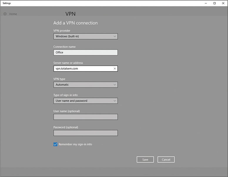
Figure 13-24 Setting up a VPN connection in Windows 10

EXAM TIP A system connected to a VPN looks as though it’s on the local network but performs much slower than if the system were connected directly back at the office, because it’s not local at all.
When your computer connects to the RRAS server on the private network, PPTP creates a secure tunnel through the Internet to the private LAN. Your client takes on an IP address of that network, as if your computer is directly connected to the LAN at the office, even down to the default gateway. In the early days of VPNs, if you opened a Web browser, your client would go across the Internet to the local LAN and then use the LAN’s default gateway to get to the Internet! Using a Web browser would be much slower when you were on a VPN. Nowadays, using a Web browser on a VPN-connected machine will use the faster local Internet connectivity, so this is not an issue.
Every operating system comes with some type of built-in VPN client that supports PPTP (among others). Figure 13-25 shows Network, the macOS VPN connection tool.

Figure 13-25 VPN on a macOS system
This type of VPN connection, where a single computer logs into a remote network and becomes, for all intents and purposes, a member of that network, is commonly called a host-to-site VPN connection.
L2TP VPNs
The VPN protocol called Layer 2 Tunneling Protocol (L2TP) took all the good features of PPTP and a Cisco protocol called Layer 2 Forwarding (L2F) and added support to run on almost any type of connection possible, from telephones to Ethernet to ultra-high-speed optical connections. The endpoint on the local LAN went from a server program to a VPN-capable router, called a VPN concentrator.
NOTE The focal point for VPN connections is called the VPN headend. This is often the VPN concentrator.
Cisco provides free client software to connect a single faraway PC to a Cisco VPN. This creates a typical host-to-site or client-to-site VPN connection. Network people often directly connect two Cisco VPN concentrators to connect two separate LANs permanently. It’s slow, but inexpensive, compared to a dedicated high-speed connection between two faraway LANs. This kind of connection enables two LANs to function as a single network, sharing files and services as if in the same building. This is called a site-to-site VPN connection.
NOTE A split tunnel VPN connection creates a secure connection to a remote network but leaves the rest of the Internet connection to the local connection. When you open a browser, in other words, and surf to www.google.com, you would go through the local, regular interface, not the VPN one. In a full tunnel VPN, in contrast, every connection goes through the remote connection. This offers security in exchange for performance; that is, full tunnel Internet connections are slug-like compared to split tunnel Internet connections.
L2TP differs from PPTP in that it has no authentication or encryption. L2TP generally uses IPsec for all security needs. Technically, you should call an L2TP VPN an “L2TP/IPsec” VPN. L2TP works perfectly well in the single-client-connecting-to-a-LAN scenario, too. Every operating system’s VPN client fully supports L2TP/IPsec VPNs.
EXAM TIP Aside from client-to-site and site-to-site VPNs, you’ll sometimes see host-to-host connections discussed. A host-to-host VPN deals with a specific single connection between two machines using VPN software or hardware.
SSL (Really TLS) VPNs
Cisco makes VPN hardware that enables SSL VPNs. These types of VPN offer an advantage over Data Link– or Network-based VPNs because they don’t require any special client software. Clientless VPN clients connect to the VPN server using a standard Web browser, with the traffic secured using Transport Layer Security (TLS), requiring no specific client-based software. (TLS replaced Secure Sockets Layer, or SSL, many years ago, but the SSL VPN moniker stuck.) The two most common types of SSL VPNs are SSL portal VPNs and SSL tunnel VPNs.
NOTE Many VPN technologies use the terms client and server to denote the functions of the devices that make the connection. You’ll also see the terms host and gateway to refer to the connections, such as a host-to-gateway tunnel.
With SSL portal VPNs, a client accesses the VPN and is presented with a secure Web page. The client gains access to anything linked on that page, be it e-mail, data, links to other pages, and so on.
With tunnel VPNs, in contrast, the client Web browser runs some kind of active control, such as Java, and gains much greater access to the VPN-connected network. SSL tunnel VPNs create a more typical host-to-site connection than SSL portal VPNs, but the user must have sufficient permissions to run the active browser controls.
DTLS VPNs
Datagram TLS (DTLS) VPNs optimize connections for delay-sensitive applications, such as voice and video over a VPN. After establishing a traditional TLS tunnel, DTLS VPNs use UDP datagrams rather than TCP segments for communication. This enhances certain types of VPN traffic. Cisco AnyConnect DTLS VPN is the prototypical example of this sort of VPN implementation.
DMVPN
Extending VPN access across a company with multiple locations can create some logistical problems. The (fictional) Bayland Widgets Corporation has a main office in Houston and two satellite offices for manufacturing, one in El Paso and the other in Laredo. A traditional VPN located at the center location would become a bottleneck for traffic. Site-to-site traffic follows a familiar pattern, with the El Paso-to-Houston and Laredo-to-Houston connections going to the central VPN. But what about connections between El Paso and Laredo? With a traditional VPN, all that traffic would route through the main VPN in Houston. That seems inefficient!
A dynamic multipoint VPN (DMVPN) fixes this problem by enabling direct VPN connections between multiple locations directly. With a DMVPN solution, traffic between El Paso and Laredo happens directly, with no need to travel through the main Houston VPN. The typical DMVPN solution, such as a Cisco DMVPN, employs standard security (IPsec) to make all the connections secure from unwanted prying.
Alternative VPNs
There are other popular VPN options beyond PPTP, L2TP, and SSL, such as OpenVPN and SSH. The most common VPN technologies today offer pure (no L2TP) IPsec solutions. These IPsec VPN technologies use IPsec tunneling for VPNs, such as Cisco IOS Easy VPN.
Another alternative is the Cisco-developed Generic Routing Encapsulation (GRE) protocol paired with IPsec for encryption. You can use GRE to make a point-to-point tunnel connection that carries all sorts of traffic over Layer 3, including multicast and IPv6 traffic. This works great for smaller implementations, but scaled up, having a unique tunnel for each node (or spoke) makes configuration of the main hub router excessive. The DMVPN solution discussed solves this by using multipoint GRE (mGRE) protocol for dynamically configured tunnels and tunnels to go to multiple destinations.
WAN Troubleshooting Scenarios
Competent network techs can recognize and deal with typical remote connectivity issues in a WAN setting. Sometimes the problem lies well beyond the job description, but that’s when the tech knows to escalate the problem. This section looks at four very important CompTIA Network+ problem areas: loss of Internet connectivity, interface errors, DNS issues, and interference.
Loss of Internet Connectivity
Given that the core reason to use all these forms of remote connectivity is to get to the Internet in the first place, I don’t look at loss of Internet connectivity as a problem. It’s more a symptom. Be sure to watch for WAN scenarios on the CompTIA Network+ exam that really aren’t always WAN scenarios.
If you want to connect a computer to the Internet, that computer needs a legitimate IP address, subnet mask, default gateway, and DNS address. These needs don’t change whether you connect through a Gigabit Ethernet wired network or through a cable modem. Use the utilities already covered in the book in such a scenario, such as ping, ipconfig, netstat, nslookup, and so forth, to verify that the device has a solid IP connection.
Interface Errors
CompTIA loves to use the term interface errors as a catchall term to describe the many connections between your computer and the remote connection that enables you to get to the Internet. In a WAN scenario you’ll have at least one more interface than in a native Ethernet world. Think about a typical office environment.
Local Ethernet Interface/LAN Interfaces
When you use DSL or cable or any other form of remote connection, it’s very easy to forget all of the LAN connections that make connectivity possible. It’s plausible, if you’re anything like me, that you’ll call an ISP like Comcast or AT&T and complain, only to find that you don’t have a patch cable plugged into the right port on the back of the computer. (Not that I’ve ever done this. Twice.)
Before you blame Comcast or AT&T for losing your connection, make sure to verify that everything on your end is in order. Is the computer properly connected to the LAN? If you are using a router, is it providing good IP information? Can you access the router and see if it is reporting that it has a proper upstream connection? Before you blame the WAN interface, always first confirm everything on the LAN.
Modem Interface
It doesn’t really matter what type of remote connection you use. There’s always a “modem.” Be careful here: “modem” is the term commonly used for any box that sits in your location and connects your LAN to the WAN, even if your ISP calls it something loftier like: cable modem, router, optical network terminal (ONT), or customer premises equipment (CPE). Everything said here that references “modem” works for whatever CPE device your ISP provides.
The modem’s job is to connect your LAN to the WAN, so by definition it’s going to have at least two interfaces: one to the LAN and one to the WAN. First of all, familiarize yourself with the lights on your modem, preferably before you have problems. Any modem is going to have a power LED, link LEDs to both the LAN and the WAN, and some form of activity LED. Study them first when you’re looking for interface issues. In almost every case of a bad interface, you’ll verify connections and reset the modem.
DNS Issues
There is one specific DNS issue that comes up in WANs: choosing what DNS server to use. Every ISP has its own DNS server(s) and, in almost every case, your modem is going to propagate those DNS settings down to every device in your LAN. In most cases there isn’t any problem with this, but there are two cases where you might want to consider manually adding DNS to your local devices or your local router. First, an ISP’s DNS servers can fail.
Second, some ISPs will help and redirect your browser to advertising or to links of possible sites you meant when you type in an incorrect URL.
In either of these cases, the rules you learned back in Chapter 9 still apply. Get yourself a fast public DNS IP address—I love the Google 8.8.8.8 and 8.8.4.4 addresses—and at the very least load one of those as a secondary DNS server.
NOTE In 2017, the Global Cyber Alliance (a group dedicated to reducing cybercrime) and IBM and other players launched Quad9, a free public DNS server that blocks the bad domains and whitelists the good domains. Phishing and scammer domains are blocked; Google and Amazon, for example, are not. Check it out by changing your DNS server to 9.9.9.9. The computer you save might be your own!
Interference
Interference at the WAN level—that CompTIA Network+ techs can fix—generally implies the connection between the LAN and the WAN. The point at which the ISP’s responsibility ends and the customer’s begins is the demarc. Let’s look at both sides of the demarc for interference.
On the customer side, the CPE can create problems. In a busy office building, for example, new installations or connections can add electromagnetic interference (EMI) and create disturbances. New things added to old environments, in other words, can create interference in existing networks.
When my company changed locations, for example, the building we moved into had several offices, connected to Internet and corporate WANs with several dedicated (ancient) T1 lines (Figure 13-26). With the local cable company offering 100-Mbps connections, we opted to have cable installed in the building for us (T1 was the dedicated network connection that ran at a whopping 1.5 Mbps).

Figure 13-26 Demarc at my office building
If the cable company had not been careful or used properly shielded boxes and cables, this could have wreaked havoc on the other folks in the building.
In a consumer space, the CPE doesn’t run into interference that would block connectivity at the demarc, unless you overly broaden the term “interference” to include “failure.” Then you can point to the “modem” as the only major failure culprit.
Once you go to the ISP side of the demarc, there’s not much interference involved, especially with existing, previously well-functioning networks. Again, WAN interference only happens if you extend the definition to include failure. Then storms, downed power lines, extraterrestrial activity, and so on can cause problems.
In a home network, there are only two times you should worry about interference in a WAN outside the demarc: during installation and when changing the connection in any way. Every form of remote connection has very clear interference tolerances, and you should have the installation tech verify this. Cable and DSL self-installations are a big issue here as most people don’t have access to the tools necessary to confirm their PSTN or coax cabling. If I’m installing a new DSL or cable modem, I refuse the self-install option and gladly pay the extra money to verify my cabling can handle the connection.
It’s incredibly easy to introduce interference into an otherwise perfectly functioning wired WAN connection by adding splitters, noisy devices, splices, and so on. This is especially true for tech folks (like your humble author) who have learned this the hard way. In general, be conservative when disturbing your WAN connection and be ready to call support if needed.
Chapter Review
Questions
1. You have just had DSL installed at your house. Although the Internet connection is fast, your phones no longer work. What is the problem?
A. The installer failed to install the POTS filters on the phones.
B. Nothing; the phones can’t function at the same time as the Internet.
C. The house phone lines can’t handle the bandwidth of both the phone and DSL.
D. The DSL modem is missing the filter and is causing line interference.
2. What protocol do cable modems use?
A. ACMSIS
B. CMAS
C. DOCSIS
D. CCSIP
3. What is SONET used for?
A. Short-distance, high-speed, fiber-optic transmission
B. Long-distance, high-speed, fiber-optic transmission
C. Long-distance, low-speed, copper cable transmission
D. Short-distance, low-speed, copper cable transmission
4. Janina needs to connect two office LANs in two different cities to function as a single network. She opts to use virtual private networking to connect the two LANs over the public Internet. What kind of VPN connection will she employ?
A. Client-to-site
B. Host-to-host
C. Point-to-point
D. Site-to-site
5. Which VPN technology enables direct connections between satellite locations?
A. PPTP VPN
B. IPsec VPN
C. SSL VPN
D. DMVPN
6. Which of the following is a protocol commonly used with today’s VPNs?
A. PPTP
B. L2TP
C. IPsec
D. PPPoE
7. Which last-mile technology enables bidirectional throughput of up to 1 Gbps?
A. Cable
B. DSL
C. Fiber
D. 4G
8. Aaron wants to connect his office to the Internet, but it’s an historic building, so he can’t run wires. Which option would give him the most throughput?
A. Cable
B. DSL
C. Fiber
D. Satellite
9. Which technology enables a private optical network within a MAN?
A. DSL
B. DOCSIS
C. Metro Ethernet
D. VPN
10. Which architecture enables fiber-to-the-home to connect the neighborhood switch to the premises?
A. DOCSIS
B. HSPA+
C. PON
D. PPPoE
Answers
1. A. The problem is the installer did not install the POTS filters on the jacks with phones attached.
2. C. Cable modems use DOCSIS, Data Over Cable Service Interface Specification.
3. B. SONET is used for long-distance, high-speed, fiber-optic transmission.
4. D. A site-to-site VPN connects LANs over the Internet.
5. D. A dynamic multipoint VPN (DMVPN) enables direct VPN connections between multiple locations.
6. C. Most VPNs use native IPsec today.
7. C. Of the listed last-mile connections, only fiber offers bidirectional throughput options of up to 1 Gbps.
8. D. Of the listed last-mile connections, only satellite provides a wireless option. (4G or 5G would work as well or better, but those aren’t listed options.)
9. C. Use metro Ethernet to create a private network within a metropolitan area using optical fiber.
10. C. Fiber-to-the-home relies on passive optical network (PON) architecture to connect a neighborhood switch to a final destination.