CHAPTER 16
Data Centers
The CompTIA Network+ certification exam expects you to know how to
• 1.2 Explain the characteristics of network topologies and network types
• 1.6 Explain the use and purpose of network services
• 1.7 Explain basic corporate and datacenter network architecture
• 2.1 Compare and contrast various devices, their features, and their appropriate placement on the network
• 2.3 Given a scenario, configure and deploy common Ethernet switching features
• 3.2 Explain the purpose of organizational documents and policies
• 3.3 Explain high availability and disaster recovery concepts and summarize which is the best solution
To achieve these goals, you must be able to
• Describe classic data center architecture and design
• Describe modern data center architecture and design
• Explain high availability concepts and procedures
• Explain best practices for documentation in the data center
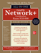
Ah, the data center—those mythical buildings that store all the data that powers our Internet sojourns. Virtually every public server—from Web, game, and e-mail servers, to DNS and certificate servers—sits in a data center, ready to respond to requests from client systems (Figure 16-1).
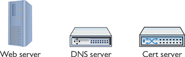
Figure 16-1 We live in data centers!
Test Specific
In a nutshell, a data center is a networked group of servers in a dedicated space—a building or part of a building—that provides data storage, Web hosting, application hosting, cloud services, and more for remote client organizations.
A data center is so much more than just a big building full of servers. A data center requires all the networking hardware to secure and effectively connect the many servers to the Internet. The data center also provides the environmental controls and physical security to protect the servers and ensure uptime. Finally, the data center contains tools necessary to protect the data center from catastrophes such as fire and natural disasters (Figure 16-2).
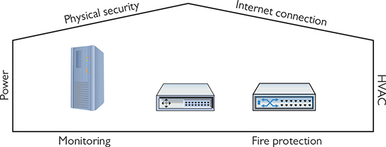
Figure 16-2 Data centers support the servers.

EXAM TIP You’ll see data centers referred to as a single word, datacenters, in the CompTIA Network+ N10-008 objectives, and as two words—data center or data centre—throughout the industry. There is no standard, so when doing research, search on all the terms.
This chapter introduces you to what it takes to build and maintain a modern data center. We’ll begin by observing classic data center architecture and design, exploring terms such as tiers and traffic flows. Next, you’ll see how virtualization and other technologies have changed important aspects of the data center with software-defined networking. Third is an interesting tour of high availability—making sure the resources offered by the data center’s servers are available when clients request them. The chapter closes by covering infrastructure support and documentation.
Classic Data Center Architecture and Design
Data centers, as a location to connect, protect, and support servers, isn’t a new concept. Arguably, the earliest generations of mainframe-based data centers date back to the late 1960s, but for purposes of this discussion, it makes sense to start with data centers populated with Internet-connected, PC-based servers from the 1990s. In smaller organizations, the data center typically is co-located at the same facility as the users it supports. In larger enterprises with multiple locations (aka branch offices), the data center is a separate, dedicated building, connected to the enterprise’s locations using dedicated connections. These external connections in the early years had names like T1/E1, OCx, ATM, and frame relay. Today these connections are usually Ethernet, MPLS, or SD-WAN (Figure 16-3).
Figure 16-3 Data center connection technologies
All these external connections are useless unless all the servers in the data centers have the internal connections necessary to get to those external connections. In other words, the data center needs a well-planned and proven architecture to ensure a reliable and efficient flow of data from the servers out to the clients.
Tiers
In a simple world where a data center consists of a couple of servers, there isn’t much in the way of architecture. You have servers, a switch, a router, and an ISP connection that might look something like Figure 16-4.

Figure 16-4 Simple data center
As the number of servers in your data center begins to grow, you need to have a structured approach to organizing your servers, switches, and routers, as well as many support systems (air conditioning systems and power especially). After decades of different architectures, the architecture most commonly adopted by traditional data centers is Cisco’s three-tiered architecture. A three-tiered architecture consists of three layers: access layer, distribution layer, and core layer (Figure 16-5).
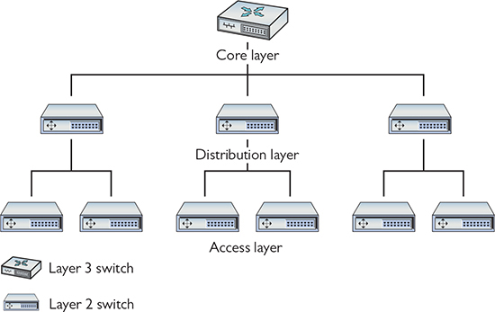
Figure 16-5 Three-tiered architecture
Access/Edge
The access layer—also referred to as the edge layer—acts as the primary connection between the data center connectivity and the users (keep in mind that “users” in the data centers are servers). The access layer is the cables and the access switches closest to the systems. A common implementation of access switches is top-of-rack switching, in which every equipment rack has one Layer 2 switch (or two for redundancy) sitting at the top of the rack, connecting to all the systems on the rack (Figure 16-6). Top-of-rack switches are co-resident in the rack with servers, as compared to switches that reside in a separate rack.

Figure 16-6 Typical rack with switch
Top-of-rack switches—dedicated switches—help keep cable runs short and well organized. Top-of-rack switching does not require that the switches be physically at the top of the rack (although they usually are). Each group of computers connected to the same access switch is known as a module.
Distribution/Aggregation Layer
Data centers have tens, hundreds, or in some cases thousands of racks in a single facility. With top-of-rack switches on all the racks, you need to provide a method to interconnect and distribute data to all the systems, acting as the connection between the access layer and the core layer. The distribution layer—also referred to as the aggregation layer—provides that connectivity. Distribution switches are usually multilayer and conduct forwarding from Layer 2 on the access side to Layer 3 for the core side. Cisco best practices recommend always having two distribution switches for each access switch. The two switches provide redundancy in case of the failure of the distribution switch or the cables that connect the distribution and access switches. Every group of modules that share the same connection to their distribution switches is known as a pod (Figure 16-7).

Figure 16-7 Distribution layer
Core
The core layer ties together all the switches at the distribution layer and acts as the point of connection to the external connections, including the Internet. All systems at this level run exclusively at OSI Layer 3 (Network layer). The interconnections here are the highest speed and the highest bandwidth and are therefore defined as the backbone. Just as with distribution, Cisco best practices recommend always having two core switches accessible to each access switch. Again, the redundancy here is warranted because of the criticality of the core switches.
Traffic Flows
All the switches, cables, and routers that populate your typical data center have a single job: to move a lot of data. To help those who design data centers, the industry has established common terms to define the movement of the data into/out of and around the data center. These are called traffic flows.
North-South
North-south traffic describes data moving into and out of the data center. While there is some variance in terms, the industry defines north-south traffic as any data leaving and entering the data center. Breaking down this term even more, northbound traffic leaves the data center and southbound traffic enters the data center.

NOTE Network devices involved in north-south traffic include edge routers, edge firewalls, and load balancers.
East-West
East-west traffic is defined as any traffic that moves between systems within the data center. Unlike north-south traffic, there is no separate east traffic or west traffic. It’s all just east-west. Examples of east-west traffic are backup traffic, intrusion detection system (IDS) alerts, and logs. Figure 16-8 shows traffic flows.

Figure 16-8 Traffic flows
NOTE Network devices involved in east-west traffic include internal routers, internal firewalls, and switches.
Data Storage
All that data moving north, south, east, and west sometimes needs to rest someplace, and that’s where data storage comes into play. For the most part, all data storage in a classic data center focuses on the mass storage devices that store the terabytes or petabytes of ones and zeroes that make up the data. Mass storage devices in a traditional data center include hard drives and tape backups. Tape backups are rare (or completely gone), making hard drives and solid-state drives (SSDs) the main technologies used to store data in data centers.
So, where are all these mass storage devices located in the data center, and what are their jobs? To be sure, every system is going to have a boot drive, in most cases a single M.2 drive mounted to the motherboard, but that drive does no more than boot the operating system. For the actual data storage, most traditional data centers use a storage area network (SAN), a network that connects individual systems to a centralized bank of mass storage (Figure 16-9). But don’t think of a SAN as simply a networked hard drive! You might remember from CompTIA A+ that hard drive storage is broken up into tiny sectors, also known as blocks. You might also remember that to access the hard drive, you have to plug it into an interface like SATA, which your operating system uses to read and write to blocks on the disk. A SAN is a pool of mass storage devices, presented over a network as any number of logical disks. The interface it presents to a client computer pretends to be a hard disk and enables the client’s operating system to read and write blocks over a network.
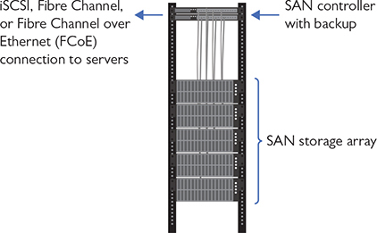
Figure 16-9 SAN in action
NOTE A lot of newer techs or techs-in-training confuse the terms SAN and NAS. Both are mass storage technologies and use the same three letters, so it’s understandable. But let’s clear up the difference right now.
SANs are high-end data storage structures that create usable and configurable storage blocks for virtual drives, virtual desktops, and more. You’re reading about them in this chapter.
Network attached storage (NAS) refers to a generally much smaller dedicated network appliance with two, four, six, or eight hard disk drives configured into some sort of array. A NAS attaches to a network switch (usually) via Ethernet and appears as available storage on the network. A NAS is used for local backups, media serving on the LAN, and other personal duties.
Think of a drive accessed through the SAN as a virtual disk. Much as the hypervisor convinces the operating system it runs on its own hardware, the SAN convinces the OS it is interacting with a physical hard drive. Just like with a traditional hard disk, we have to format a virtual disk before we can use it. But unlike a traditional hard disk, the virtual disk the SAN presents could be mapped to a number of physical drives in various physical locations or even to other forms of storage.
One of the benefits of using a SAN is that, by just reading and writing at the block level, it avoids the performance costs of implementing its own file system. The SAN leaves it up to the client computers to implement their own file systems—these clients often use specialized shared file system software designed for high volume, performance, reliability, and the ability to support multiple clients using one drive.
When it comes to the infrastructure to support a SAN, there are currently two main choices:
• Fibre Channel (FC) is, for the most part, its own ecosystem designed for high-performance storage. It has its own cables, protocols, and switches, all increasing the costs associated with its use. While more recent developments like Fibre Channel over Ethernet (FCoE) make Fibre Channel a little more flexible within a local wired network, long-distance FC is still clumsy without expensive cabling and hardware.
• Internet Small Computer System Interface (iSCSI) is built on top of TCP/IP, enabling devices that use the SCSI protocol to communicate across existing networks using cheap, readily available hardware. Because the existing networks and their hardware weren’t built as a disk interface, performance can suffer. Part of this performance cost is time spent processing frame headers. We can ease some of the cost of moving large amounts of data around the network at standard frame size by using jumbo frames. Jumbo frames are usually 9000 bytes long—though technically anything over 1500 qualifies—and they reduce the total number of frames moving through the network.
NOTE The physical connections between the systems and the SAN are usually fiber optics.
Moving a server’s data storage physically apart from the server adds some risk. If the SAN fails, the server won’t function. To address this risk, most SAN solutions provide more than one connection or path between the server and the SAN, what’s called multipathing. If either connection fails, the other connection continues to keep the server connected to the SAN. A SAN is developed with high availability in mind, so it often includes features such as redundant controllers and power supplies, plus shared memory. All this is in addition to multipathing. (See “High Availability in the Data Center” later in the chapter for more details.)
Where Is the Classic Data Center?
So, where does the data center physically exist? That answer varies based on where and how an organization stands in terms of growth. A tiny company might leave all of its data sitting on a single computer in the founder’s garage. As a company grows and its data requirements grow, it faces choices. Does it build an on-premises data center, a dedicated data center at the company’s site?
For many organizations, the next step is to build a rack in an empty room and load it with a few servers and mass storage devices, in essence, building a mini data center. That is perfectly fine for small organizations, but as data and server needs progress even further, a true data center is required. It’s time to take the servers and move them into a proper, secure, reliable, classic data center.
But where to place this beast? On-premises data centers are wildly expensive in terms of both the building and the associated maintenance and upkeep. Back in the day, there really weren’t any other viable choices. Over time, however, clever entrepreneurs (or folks who had already built data centers and had extra capacity) began to offer public, third-party data centers where anyone could place their own servers, a process known as co-location.
There’s one more step in the growth of an organization that will affect the data center: multiple locations. As an organization grows into multiple locations, there’s usually a central location (often corporate headquarters) that contains an organization’s single data center. This data center serves outlying offices, called branch offices. The branch offices themselves store very little data.
EXAM TIP Expect a question on the CompTIA Network+ exam that compares branch office versus on-premises data center versus colocation (with no hyphen). That would be remote connections to a data center versus an on-site data center versus a data center hosted by a third party.
The Modern Data Center
The first few decades of traditional data centers were populated with dedicated, monolithic hardware. Servers served one Web site or one function such as DNS. Routers and switches were dedicated boxes that performed only a single job, routing or switching. Monolithic devices worked well back in the day, but the introduction of virtualization and software-defined networking changed the data center dramatically, creating the modern data center.
Virtualization
Virtualization redefined the architecture of the data center. Where once physical servers ran single copies of Web servers and other individual applications, physical servers today are nothing more than hypervisors, running two, three, perhaps even 20 virtual servers each. There might be a few non-virtual (bare-metal) systems, but these apply almost always to very special situations such as SAN controllers. If you have a server in a data center today, it most likely is virtualized.
Software-Defined Networking
Virtualization doesn’t stop with servers. Interconnections that once used dedicated switches have moved to software-defined networking (SDN) devices (that you read about in Chapter 15), making far more flexible and powerful data center architectures. There are still physical switches out in the data center; it’s just that they’ve been relegated to act as only the underlayment, the path for mainly virtualized VLAN trunks to move far more complex architectures.
Spine and Leaf
Virtualization and SDN freed the data center from the three-tiered model. In particular, virtualization removes the need for the distribution/aggregation layer. With a spine-and-leaf architecture, every spine switch connects to every leaf switch in a two-tiered mesh network (Figure 16-10). The mesh network removes the need for dedicated connections between the spine backbone switches, because traffic moves seamlessly from spine to leaf to spine, regardless of how many spine or leaf switches are on the network.

Figure 16-10 Spine-and-leaf architecture
NOTE Spine-and-leaf configurations have multiple, interconnected top-of-rack structures.
Spine-and-leaf architecture has some real benefits compared to three-tiered architecture. First, spine-and-leaf architecture reduces the number of necessary devices. Every step from the spine to leaf is a single hop, which reduces latency and creates completely predictable connections. Also, there’s no longer a concern for loops, making Spanning Tree Protocol (STP) unneeded. Virtual servers today rely heavily on data from other servers in the same data center, adding far more east-west traffic than is easily handled by three-tiered architecture. Spine-and-leaf architecture handles east-west traffic with ease. Spine-and-leaf architecture uses protocols such as Equal-Cost Multipath (ECPM) to provide load balancing across the paths so that no single connection gets overwhelmed.
Finally, spine-and-leaf architecture makes adding capacity simpler than in a three-tiered architecture. You can add another spine switch and connect it to every leaf switch through the mesh network; new leaf switches that are added simply slot in to reduce the load on all the other leaf switches.
EXAM TIP The CompTIA Network+ objectives refer to a spine-and-leaf architecture network as a software-defined network. This is odd terminology. Data centers certainly use SDN, but that includes both three-tier and spine-and-leaf-type data centers. Don’t miss it if you see this on the exam.
High Availability in the Data Center
If there’s one thing that a data center must do well, it is to provide the right data to the right host at the right time, without ever dropping or failing. Unfortunately, things fail in life: CPUs melt, rodents chew cables, and power supplies die. Therefore, it’s important to ensure systems keep working without interruption or downtime; in other words, to make sure critical systems have high availability (HA). Some of the concepts of HA have been covered previously in the book and even in this chapter, such as multipathing within a SAN; as the concepts come into play here, I’ll point to where you read about them previously. HA in this section explores load balancing, redundancy, and facilities and infrastructure support.
Load Balancing
As a concept, load balancing means to share among two or more systems the effort to enable some process to work. You saw this concept way back in Chapter 11 in the context of using multiple servers as a server cluster that manifests as a single entity. Special-purpose load balancers help apportion the work among the various servers. You’ve seen the concept used in spine-and-leaf data centers earlier that rely on protocols like ECPM to balance the work among the various switches so that no single connection gets swamped. Load balancing in its many forms is one pillar of high availability.
Clustering, in the traditional sense, means to have multiple pieces of equipment, such as servers, connected in a manner that appears to the user and the network as one logical device, providing data and services to the organization. Clusters usually share high-speed networking connections as well as data stores and applications and are configured to provide redundancy if a single member of the cluster fails.
NOTE Clustering solutions are commonly active-active examples of high availability in that all members of the cluster are active at the same time.
Redundancy
Redundancy ensures high availability on many levels through the use of additional equipment and connection options. If one device or connection goes down, another takes its place.
With redundant hardware/clusters, you put into place primary switches, routers, firewalls, and other network gear, then have at the ready backup machines to step up in case the primary machine fails. Core to building high availability into a network is failover, the ability for backup systems to detect when a master has failed and then to take over.
If you’re going to use multiple devices to do one job, there must be a way to make multiple devices look like a single device to the rest of the devices. This is commonly done by having multiple devices share a single external MAC address or IP address while using their own internal MACs or IPs to communicate with each other. You’ll see this concept over and over again.
Building with high availability in mind extends to more than just servers; a default gateway, for example, is a critical node that can be protected by adding redundant backups. Protocols that support HA and redundancy are referred to as first hop redundancy protocols (FHRPs) and include the open standard Virtual Router Redundancy Protocol (VRRP) and the Cisco-proprietary Hot Standby Router Protocol (HSRP) and Gateway Load Balancing Protocol (GLBP). The nice thing about VRRP, HSRP, and GLBP is that, conceptually, they perform the same function. They take multiple routers and gang them together into a single virtual router with a single virtual IP (VIP) address that clients use as a default gateway. This includes making redundant firewalls on the redundant routers! GLBP takes things a step further, providing full load balancing as well.
EXAM TIP VRRP and HSRP are examples of active-passive high availability in that only one router is active at a time. All other routers are passive until the active router fails.
Redundancy applies to connections as well as systems. What’s an absolutely critical connection point for a data center? Connection to the Internet should never be a single point of failure for a data center (or for any organization, for that matter). It’s common for a data center to use multiple Internet service providers (ISPs) so that if one service goes down, the other ISP provides continued Internet connectivity. Sometimes the other ISP is a hot standby, so the Internet connection switches, a failover. Other setups have the secondary ISP actively engaged and available for excess traffic, and is in place to be the sole service if necessary. Employing multiple ISPs is a measure of fault tolerance.
It’s very common for ISPs to share common lines and such, especially when they are servicing the same physical location. It’s therefore critically important to ensure path diversity, where the lines out of your ISP follow diverse paths to other routers. A common method for path diversity in smaller centers, for example, uses a fiber connection for the primary path and a very fast cellular connection as a failover. Use of both a fiber ISP and a different cable ISP can also lead to path diversity.
Facilities and Infrastructure Support
Data centers require proper support for facilities and infrastructure, which means ensuring proper power, clean cool air for components, and emergency procedures are in place. All of these add to high availability and, in the case of the last item, disaster recovery.
Power
Rack-mounted equipment has a number of special power needs. At an absolute minimum, start with a proper power source. A single small rack can get away with a properly grounded, 20-amp dedicated circuit. Larger installations can require larger, dedicated power transformers supplied by the local power grid.
NOTE Different rack manufacturers have specific rules and standards for rack electrical grounding. Refer to the specific manufacturer’s installation instructions and consider hiring professional installers when placing your racks.
When you get down to individual racks, it’s always a good idea to provide each rack with its own rack-mounted uninterruptible power supply (UPS)—a battery backup and power conditioner. You then connect a power distribution unit (PDU)—a rack-mounted set of outlets for devices—to that UPS. If you’re using power converters for devices that require DC rather than AC, always use a single power converter per rack.
The more-demanding equipment room also demands more robust power and battery backup. A single, decent UPS might adequately handle brief power fluctuations for a single rack, for example, but won’t be able to deal with a serious power outage. For that kind of power redundancy—keeping the lights on and the servers rolling—you’d need to connect power generators to the equipment room, devices that burn some petroleum product to produce electricity when the main grid goes dark.
Environment
Racks with servers, switches, routers, and such go into closets or server rooms and they dump heat. The environment within this space must be monitored and controlled for both temperature and humidity. Network components work better when cool rather than hot.
The placement of a rack should optimize the airflow in a server area. All racks should be placed so that components draw air in from a shared cool row and then exhaust the hot air into a hot row.
The heating, ventilation, and air conditioning (HVAC) system should be optimized to recirculate and purify the hot air into cool air in a continuous flow. What’s the proper temperature and humidity level? The ideal for the room, regardless of size, is an average temperature of 68 degrees Fahrenheit and ~50 percent humidity. A proper fire suppression system—one that can do things like detect fire, cut power to protect sensitive equipment, displace oxygen with fire-suppressing gasses, alert relevant staff, and activate sprinklers in a pinch—is an absolute must for any server closet or room. You need to extinguish any electrical spark quickly to minimize server or data loss.
Emergency Procedures
A data center must have proper emergency procedures in place before the emergencies happen. This is essential risk management. Here are five essential aspects that should be covered:
• Building layout
• Fire escape plan
• Safety/emergency exits
• Fail open/fail close
• Emergency alert system
Exit plans need to cover building layout, fire escape plans, and the locations of emergency exits. Exit signs should be posted strategically so people can quickly exit in a real emergency.
Secured spaces, such as server rooms, need some kind of default safety mechanism in case of an emergency. Emergency exits like stairways also require safety mechanisms like fail safe locks. Locked doors need to fail open—doors default to open in case of emergency—or fail closed—doors lock in case of emergency. Fail safe locks, such as maglocks, require power to stay locked. When the power goes out, they automatically open. The contrasting locks are called fail secure. They’re locked by default and require power to open. If they power goes out, they stay locked.
Finally, nothing beats a properly loud emergency alert system blaring away to get people moving quickly. Don’t forget to have annual fire drills and emergency alert mixers to make certain all employees know what they need to know.
Documenting the Data Center
A properly organized data center requires extensive documentation that describes every aspect of the organization, from physical layout to electrical structure, from networking standards and installations to climate control systems. This documentation includes the people necessary to maintain, repair, and replace every piece of equipment. Every applicable government standard needs to be included in the proper place in the documentation. And at least annually, the data center (and its documentation) should be reviewed and audited for efficiency and compliance. As you might imagine at this point, properly documenting a data center is a major continuous undertaking and not a task that should be shirked at all.
Here’s the scenario. The Wapi Lava Corporation (WLC), based in Pocatello, Idaho, has a midsize data center (nicknamed “Hot Flo”) in the basement of a downtown building. The city of Pocatello was chosen because of the availability of inexpensive electricity, good connectivity with the West Coast and solid links to the Midwest, and very low probability of natural disasters. This section explores the data center documentation in three categories:
• Network diagrams
• Baseline configurations
• Assessments
NOTE The fictitious Wapi Lava Corporation is named after the Wapi Lava Field, a very inactive volcanic site around 30 miles outside the city of Pocatello. It hasn’t erupted in more than 2000 years. (It’s pronounced WAH-pie.)
Network Diagrams
Good data center documentation contains all sorts of diagrams, mapping out physical and logical systems. These documents include dimensions, standards followed, locations, connectivity, technology manufacturers and model numbers, licensing, essential personnel, and more.
Physical Network Diagrams
Physical network diagrams map out physical aspects of the data center, including floor plans, rack diagrams, and documents describing the physical components and connectivity in the centralized wiring rooms on each floor.
Physical network diagrams rely on a few standard tools for layout, such as Microsoft Visio, Wondershare Edraw, or my current favorite, diagrams.net. Figure 16-11 shows some of the icons available in diagrams.net.

Figure 16-11 Icon options in the diagrams.net app
Floor Plans
A data center floor plan includes the dimensions and locations of rooms, like the simple floor plans you read about way back in Chapter 5, but expand dramatically to include details. Floor plans include locations of—and detailed information about—racks, hot and cold aisles, raised floors, ceiling heights, air conditioning units, ductwork, and so on. Floor plan documentation can take many pages, illustrations, and discussion.
Figure 16-12 shows the basic layout of the lower level of Hot Flo. Note the three major sections. There is a wiring room in the west (left), a network operations center in the center, and the server farm in the east (right).

Figure 16-12 Basic layout of WLC’s data center lower floor
The wiring room is the intermediate distribution frame (IDF) that serves as the wiring focal point for all the devices on that floor. This is also called a telecommunications room, like you read about in Chapter 5. The network operations center (NOC) houses network engineers and technicians who maintain the applications housed in the data center, such as databases, Web servers, and so forth. The vast majority of the lower level is the server farm, with row upon row of racks holding stacks of servers. Each rack is topped with two switches.
Figure 16-13 drills down further into the server farm area, showing the hot aisles—where heat can go away from the servers—and cold aisles—where the air conditioning vents pump cold air for thirsty servers.

Figure 16-13 Floor plan details of server farm
Figure 16-14 shows the upper-floor layout—although without individual offices mapped—with both a telecommunications room for the floor and a main distribution frame (MDF) that holds all the equipment that enables Hot Flo’s connection to the outside world.
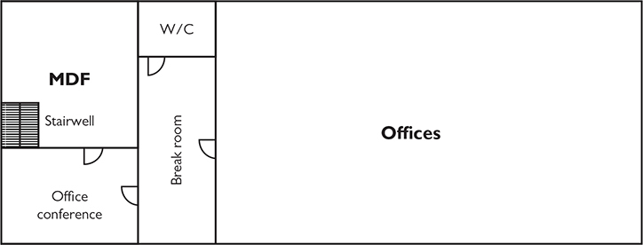
Figure 16-14 Upper-level floor plan of WLC’s data center
Rack Diagrams
Drilling down for more details, each rack (in the server farm and the IDFs and MDF) has a detailed rack diagram with a ton of details. Figure 16-15 shows one such rack. Note that the location and make and model of each component on the rack is labeled. Appended to this illustration is further documentation that has the current firmware version, date of purchase, upgrade history, service history, technician in charge of servicing, vendor contact, licensing information, and more.

Figure 16-15 Rack diagram
MDF/IDF Documentation
The main distribution frame and intermediate distribution frames provide connectivity to the outside world (MDF) and network connectivity within each floor (IDF). They require unique and detailed documentation of the overall layout and connections, plus specific rack diagrams for their various components. Figure 16-16 shows the MDF documentation. The figure provides details about the demarc connection and the rack holding the patch panels and switches that provide further connectivity within the data center, and the uninterruptible power supply providing clean power to the rack components. The make and model of each component are clearly labeled.

Figure 16-16 Basic MDF layout
Just as with the server farm rack described earlier, further documentation accompanies the MDF racks that detail firmware versions, service and upgrade records, assigned technicians, vendor contacts, and so on.
Logical Network Diagrams
Essential network documentation includes logical network diagrams, line drawings that show the connectivity among the many devices in the network. Figure 16-17 shows the server farm portion of the WLC data center. Accompanying the logical drawing would be pages of additional documentation, including specific wiring standards used, vendor information, and so on.

Figure 16-17 Logical network diagram showing the WLC data center server farm
Wiring Diagrams
Wiring diagrams can show any number of types of wiring, from the full electrical map in Figure 16-18 to a detailed layout of the physical space with drops to each workstation and full cable runs. Wiring diagrams and the detailed additional documents provide absolutely essential network documentation for the data center.

Figure 16-18 Wiring diagram showing the electrical components and connections in the server farm of the WLC data center
Baseline Configurations
Once the data center is up and running and efficiently humming along, the baseline configuration documents all the components of the data center. Note that this is a network baseline rather than a performance baseline—the latter examines throughput, bandwidth, and the like. A baseline configuration describes all the pieces, including portable computers, servers, switches, routers, and so on, plus all the software packages installed on everything. The baseline configuration also includes network topology and placement of devices in the organization.
The baseline configuration provides the foundation for future upgrades. When any upgrades happen, the organization should update the baseline configuration documentation to the new baseline.
NOTE This definition of baseline configuration reflects the best practices outlined in NIST Special Publication 800-128, Guide for Security-Focused Configuration Management of Information Systems.
Assessments
Periodically, every data center should be assessed for overall efficiency and effectiveness. Is every component performing up to expectations? Does the current performance meet the goals of the organization? Is everything in the network in compliance with current national or international laws and regulations?
The assessments can be conducted by an external party or an internal division. The benefit of the former is that an external party has no preconceptions or bias toward any specific system or individuals (in theory). The benefit of the latter is that an internal division has much more familiarity with how data center operations are supposed to work to accomplish the organization’s goals.
Site Surveys
A periodic site survey queries everything about the data center. This starts with an overall assessment and then drills down into each category. The following categories should be included in the site survey report:
• Layout and space utilization
• Infrastructure installed
• Expectations for the organization
• Future requirements
• Concerns about current performance
Drilling down, inspections should cover exhaustive details. For layout and space utilization, for example, examiners should inspect, and create detailed reports that include, at least the following:
• General layout
• Space utilization
• Thermal management
• Electrical distribution
• Cabling types and paths
• Racks, cabinets, server locations
• Labeling compliance with ANSI/TIA 606-C
Every category examined by the site survey team would get equally granular into aspects pertaining to that category.
The site survey final documentation—the site survey report—provides not only a picture of the current state of the data center, but also recommendations for improvements in any number of areas. The site survey is an essential piece of data center maintenance and development.
Audit and Assessment Reports
Annually at least, a data center should have a thorough audit that assesses compliance with every applicable law and regulation for the industry. This audit should be conducted by an outside organization that specializes in auditing, to avoid any potential conflict of interest or bias. The laws and regulations that almost certainly apply include the following:
• ISO 27001 Standard that helps organizations manage and secure assets by making and implementing an information security management system (ISMS). An ISMS enables organizations to categorize and organize their many security controls—measures put in place to lock down the many systems employed.
• ISO 27002 Standard that helps organizations manage security policies on every level.
• Health Insurance Portability and Accountability Act (HIPAA) U.S. federal law that regulates how organizations manage health information data to protect the privacy of individuals and other entities.
• Payment Card Industry Data Security Standard (PCI DSS) Standard for protecting credit card and other financial information exchanged between the organization and outside entities. The data center absolutely needs to be PCI DSS compliant.
The standards mentioned here are the tip of the iceberg when it comes to the laws and regulations governing organizations such as data centers. The highly detailed and technical nature of each of these laws and regulations makes yet another compelling case for using an outside firm to do the audit. At the end of an audit, the auditing firm produces an assessment report that details all findings and recommendations for upgrades, fixes for compliance, and so on.
Chapter Review
Questions
1. Which of the following data center implementations connects access layer to distribution layer to core layer?
A. North-south traffic flow
B. Spine-and-leaf architecture
C. Three-tiered architecture
D. Top-of-rack switching
2. Which SAN feature provides high availability through more than one connection between the server and the SAN?
A. Fibre Channel
B. iSCSI
C. Multipathing
D. Multiplaning
3. Blackwell Held, LLC, leases space in the Wapi Lava Corporation’s data center. Which term describes this type of scenario?
A. Branch office
B. Co-location
C. Leased-line
D. On-premises
4. Which of the following protocols provides load balancing in a spine-and-leaf data center?
A. ECPM
B. HSRP
C. STP
D. VRRP
5. Joan’s data center has two ISPs, one fiber and one cable. What aspect of security does this represent?
A. Active-active
B. Clustering
C. Multipathing
D. Redundancy
6. Which open standard protocol enables redundant routers to appear as a single router for high availability?
A. HSRP
B. RRPX
C. VRRP
D. XRRP
7. Brenda wants to add a second ISP to her small data center for high availability. What should she consider?
A. Fiber
B. Multipath
C. Multitenancy
D. Path diversity
8. Which of the following documentation includes dimensions and locations of rooms plus the physical objects—racks, raised floors, AC units, and so on—in the space?
A. Floor plan
B. Logical network diagram
C. Rack diagram
D. System diagram
9. Which document contains details about all the hardware and software installed in a data center and provides the foundation for future upgrades?
A. Baseline configuration
B. Logical network diagram
C. Performance baseline
D. System diagram
10. Which of the following is a review of an organization’s compliance with applicable laws, rules, and regulations?
A. Audit
B. Baseline configuration
C. Performance baseline
D. Site survey
Answers
1. C. The three-tiered architecture connects three layers—access, distribution, and core—in the classic data center.
2. C. Most storage area network (SAN) solutions use multipathing—more than one connection or path between the server and SAN—for high availability.
3. B. Leasing space for your equipment in someone else’s space is an example of co-location.
4. A. Equal-Cost Multipath (ECPM) is one protocol used in spine-and-leaf architecture that provides load balancing.
5. D. Having multiple Internet service providers (ISPs) for a data center provides redundancy.
6. C. Virtual Router Redundancy Protocol (VRRP) groups multiple routers into a single router for high availability. The Cisco-proprietary Hot Standby Router Protocol (HSRP) accomplishes the same thing, but it’s not an open standard.
7. D. Path diversity in selecting a second ISP—making sure both ISPs don’t share the same lines—enhances high availability.
8. A. A floor plan includes room dimensions and the details of objects in those rooms.
9. A. A baseline configuration document contains details about all the installed hardware and software in a data center, and provides the foundation for future upgrades.
10. A. An audit, performed at least annually by a qualified third-party organization, will show an organization’s compliance with applicable laws, rules, and regulations.