CHAPTER 5
Installing a Physical Network
The CompTIA Network+ certification exam expects you to know how to
• 1.2 Explain the characteristics of network topologies and network types
• 1.3 Summarize the types of cables and connectors and explain which is the appropriate type for a solution
• 3.2 Explain the purpose of organizational documents and policies
• 3.3 Explain high availability and disaster recovery concepts and summarize which is the best solution
• 5.2 Given a scenario, troubleshoot common cable connectivity issues and select the appropriate tools
To achieve these goals, you must be able to
• Recognize and describe the functions of basic components in a structured cabling system
• Explain the process of installing structured cable
• Install a network interface card
• Perform basic troubleshooting on a structured cable network
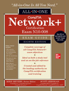
Armed with the knowledge of previous chapters, it’s time to construct a physical network. This might seem easy; after all, the most basic network is nothing more than a switch with cables snaking out to all of the PCs on the network (Figure 5-1).

Figure 5-1 What an orderly looking network!
On the surface, such a network setup is absolutely correct, but if you tried to run a network using only a switch and cables running to each system, you’d have some serious practical issues. In the real world, you need to deal with physical obstacles like walls and ceilings. You also need to deal with people. People are incredibly adept at destroying physical networks. They unplug switches, trip over cables, and rip connectors out of NICs with incredible consistency unless you protect the network from their destructive ways. Although the simplified switch-and-a-bunch-of-cables type of network can function in the real world, the network clearly has some problems that need addressing before it can work safely and efficiently (Figure 5-2).
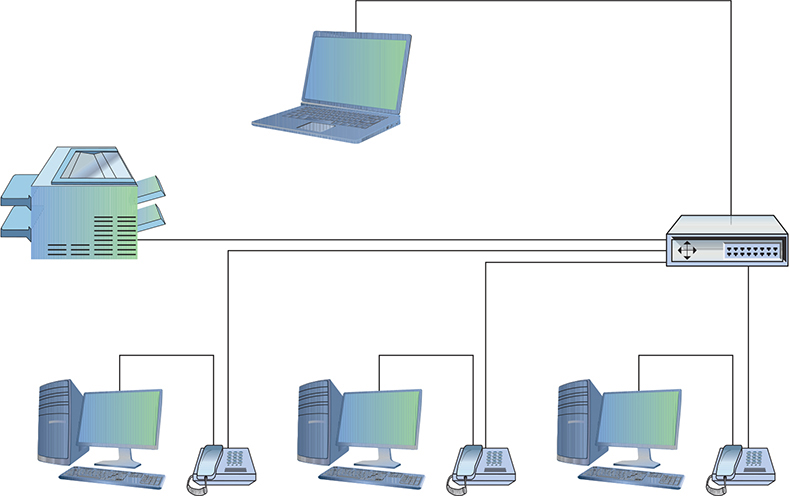
Figure 5-2 A real-world network
This chapter takes the abstract discussion of network technologies from previous chapters into the concrete reality of real networks. To achieve this goal, it marches you through the process of installing an entire network system from the beginning. The chapter starts by introducing you to structured cabling, the critical set of standards used all over the world to install physical cabling in a safe and orderly fashion. It then delves into the world of larger networks—those with more than a single switch—and shows you some typical methods used to organize them for peak efficiency and reliability. Next, you’ll take a quick tour of the most common NICs used in PCs, and see what it takes to install them. Finally, you’ll look at how to troubleshoot cabling and other network devices, including an introduction to some fun diagnostic tools.
Historical/Conceptual
Understanding Structured Cabling
If you want a functioning, dependable, real-world network, you need a solid understanding of a set of standards and proprietary systems, collectively called structured cabling. In the United States, the Telecommunications Industry Association (TIA) gives professional cable installers detailed standards on every aspect of a cabled network, from the type of cabling to use to the position of wall outlets. The European Union has adopted some of the TIA standards, but publishes versions with various bodies such as Europe Norm (EN) and CENELEC.

NOTE The Electronic Industries Alliance (EIA) ceased operations in 2011, but various groups (like TIA) maintain the standards. You’ll see in a lot of literature the standards body listed as TIA/EIA for that reason, including on the CompTIA Network+ exam and in this book.
The CompTIA Network+ exam requires you to understand the basic concepts involved in designing a network and installing network cabling and to recognize the components used in a real network. The CompTIA Network+ exam does not, however, expect you to be as knowledgeable as a professional network designer or cable installer. Your goal is to understand enough about real-world cabling systems to communicate knowledgeably with cable installers and to perform basic troubleshooting. Granted, by the end of this chapter, you’ll have enough of an understanding to try running your own cable (I certainly run my own cable), but consider that knowledge a handy bit of extra credit.
The idea of structured cabling is to create a safe, reliable cabling infrastructure for all of the devices that may need interconnection. Certainly this applies to computer networks, but also to telephone, video—anything that might need low-power, distributed cabling.
NOTE A structured cabling system is useful for more than just computer networks. You’ll find structured cabling defining telephone networks and video conferencing setups, for example.
You should understand three issues with structured cabling. Cable basics start the picture, with switches, cabling, and PCs. You’ll then look at the components of a network, such as how the cable runs through the walls and where it ends up. This section wraps up with an assessment of connections leading outside your network.
NOTE Most networks today have a wireless component in addition to a wired infrastructure. The switches, servers, and workstations rely on wires for fast and stable networking, but the wireless component supports the large number of laptops, phones, and other devices found in a modern network. This chapter focuses on the wired infrastructure. Once we get through Wi-Fi in Chapter 14, I’ll add that component to our networking conversation.
Cable Basics—A Star Is Born
This exploration of the world of connectivity hardware starts with the most basic of all networks: a switch, some UTP cable, and a few PCs—in other words, a physical star network (Figure 5-3).

Figure 5-3 A switch connected by UTP cable to two PCs
No law of office decor prevents you from installing a switch in the middle of your office and running cables on the floor to all the computers in your network. This setup works, but it falls apart spectacularly when applied to a real-world environment. Three problems present themselves to the network tech. First, the exposed cables running along the floor are just waiting for someone to trip over them, damaging the network and giving that person a wonderful lawsuit opportunity. Possible accidents aside, simply moving and stepping on the cabling will, over time, cause a cable to fail due to wires breaking or RJ-45 connectors ripping off cable ends. Second, the presence of other electrical devices close to the cable can create interference that confuses the signals going through the wire. Third, this type of setup limits your ability to make any changes to the network. Before you can change anything, you have to figure out which cables in the huge rat’s nest of cables connected to the switch go to which machines. Imagine that troubleshooting nightmare!
“Gosh,” you’re thinking, “there must be a better way to install a physical network.” A better installation would provide safety, protecting the star from vacuum cleaners, clumsy coworkers, and electrical interference. It would have extra hardware to organize and protect the cabling. Finally, the new and improved star network installation would feature a cabling standard with the flexibility to enable the network to grow according to its needs and then to upgrade when the next great network technology comes along.
As you have no doubt guessed, I’m not just theorizing here. In the real world, the people who most wanted improved installation standards were the ones who installed cable for a living. In response to this demand, TIA and other standards bodies developed standards for cable installation. The TIA/EIA 568 standards you learned about in Chapter 3 are only some of the standards all lumped together under the umbrella of structured cabling.
Installing structured cabling properly takes a startlingly high degree of skill. Thousands of pitfalls await inexperienced network people who think they can install their own network cabling. Pulling cable requires expensive equipment, a lot of hands, and the ability to react to problems quickly. Network techs can cost employers a lot of money—not to mention losing their good jobs—by imagining they can do it themselves without the proper knowledge.
If you are interested in learning more details about structured cabling, an organization called the Building Industry Consulting Service International (BICSI; www.bicsi.org) provides a series of widely recognized certifications and training courses for the cabling industry.
Test Specific
Structured Cable—Network Components
Successful implementation of a basic structured cabling network requires three essential ingredients: a telecommunications room, horizontal cabling, and a work area. Let’s zero in on one floor of Figure 4-10 from the previous chapter. All the cabling runs from individual PCs to a central location, the telecommunications room (Figure 5-4). What equipment goes in there—a switch or a telephone system—is not important. What matters is that all the cables concentrate in this one area.

Figure 5-4 Telecommunications room
All cables run horizontally (for the most part) from the telecommunications room to the PCs. This cabling is called, appropriately, horizontal cabling. A single piece of installed horizontal cabling is called a run. At the opposite end of the horizontal cabling from the telecommunications room is the work area. The work area is often simply an office or cubicle that potentially contains a PC and a telephone. Figure 5-5 shows both the horizontal cabling and work areas.

Figure 5-5 Horizontal cabling and work area
Each of the three parts of a basic star topology network—the telecommunications room, the horizontal cabling, and the work area(s)—must follow a series of strict standards designed to ensure that the cabling system is reliable and easy to manage. The cabling standards set by TIA/EIA enable techs to make sensible decisions on equipment installed in the telecommunications room, so let’s tackle horizontal cabling first, and then return to the telecommunications room. We’ll finish up with the work area.
Horizontal Cabling
A horizontal cabling run is the cabling that goes more or less horizontally from a work area to the telecommunications room. In most networks, this cable is Cat 5e or better UTP for copper-based standards, such as 1000BASE-T. (Fiber-based standards, such as 1000BASE-SX, would use multimode fiber-optic cabling, also in a star topology.) When you move into structured cabling, the TIA/EIA standards define a number of other aspects of the cable, such as the type of wires, number of pairs of wires, and fire ratings.

EXAM TIP A single piece of cable that runs from a work area to a telecommunications room is called a run.
Solid Core vs. Stranded Core All UTP cables come in one of two types: solid core or stranded core. Each wire in solid core UTP uses a single solid wire. With stranded core, each wire is actually a bundle of tiny wire strands. Each of these cable types has its benefits and downsides. Solid core is a better conductor, but it is stiff and will break if handled too often or too roughly. Stranded core is not quite as good a conductor, but it will stand up to substantial handling without breaking. Figure 5-6 shows a close-up of solid and stranded core UTP.

Figure 5-6 Solid and stranded core UTP
TIA/EIA specifies that horizontal cabling should always be solid core. Remember, this cabling is going into your walls and ceilings, safe from the harmful effects of shoes and vacuum cleaners. The ceilings and walls enable you to take advantage of the better conductivity of solid core without the risk of cable damage. Stranded core cable also has an important function in a structured cabling network, but I need to discuss a few more parts of the network before I talk about where to use stranded core UTP cable.
Number of Pairs Pulling horizontal cables into your walls and ceilings is a time-consuming and messy business, and not a process you want to repeat, if at all possible. For this reason, most cable installers recommend using the highest Cat rating you can afford. Many years ago, I would also mention that you should use four-pair UTP, but today, four-pair is assumed. Four-pair UTP is so common that it’s difficult, if not impossible, to find two-pair UTP. Cat 5e, Cat 6, Cat 6a, Cat 7, etc. all use four-pair UTP.
You’ll find larger bundled UTP cables in legacy telephone installations. These cables hold 25 or even 100 pairs of wires (Figure 5-7). These cables are not used for Ethernet.
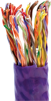
Figure 5-7 25-pair UTP
Choosing Your Horizontal Cabling Network installations today favor at least Cat 6. Installing higher-rated cabling—Cat 6a, 7, etc.—is done either as a hedge against new network technologies that may require a more advanced cable or simply adoption of the faster 10+ Gigabit standards.
The Telecommunications Room
The telecommunications room is the heart of the basic star topology network. This room—technically called the intermediate distribution frame (IDF)—is where all the horizontal runs from all the work areas come together. The concentration of all this gear in one place makes the telecommunications room potentially one of the messiest parts of the basic star topology network. Even if you do a nice, neat job of organizing the cables when they are first installed, networks change over time. People move computers, new work areas are added, network topologies are added or improved, and so on. Unless you impose some type of organization, this conglomeration of equipment and cables decays into a nightmarish mess.
NOTE The telecommunications room is also known as the intermediate distribution frame (IDF), as opposed to the main distribution frame (MDF), which we will discuss later in the chapter.
Fortunately, the TIA/EIA structured cabling standards define the use of specialized components in the telecommunications room that make organizing a snap. In fact, it might be fair to say that there are too many options! To keep it simple, we’re going to stay with the most common telecommunications room setup and then take a short peek at some other fairly common options.
Equipment Racks The central component of every telecommunications room is one or more equipment racks. An equipment rack provides a safe, stable platform for all the different hardware components. All equipment racks are 19 inches wide, but they vary in height from two- to three-foot-high models that bolt onto a wall (Figure 5-8) to the more popular floor-to-ceiling models, free-standing racks (Figure 5-9).

Figure 5-8 A short equipment rack
Figure 5-9 A free-standing rack
NOTE Equipment racks evolved out of the railroad signaling racks from the 19th century. The components in a rack today obviously differ a lot from railroad signaling, but the 19-inch width has remained the standard for well over 100 years.
You can mount almost any network hardware component into a rack. All manufacturers make rack-mounted switches that mount into a rack with a few screws. These switches are available with a wide assortment of ports and capabilities. There are even rack-mounted servers, complete with slide-out keyboards, and rack-mounted uninterruptible power supplies (UPSs) to power the equipment (Figure 5-10). A UPS provides backup power to the devices on the rack. (See “Problems in the Telecommunication Room” later in this chapter for more details.)
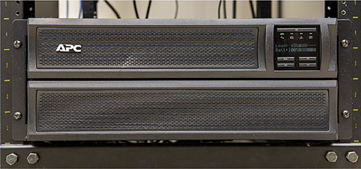
Figure 5-10 A rack-mounted UPS
All rack-mounted equipment uses a height measurement known simply as a unit (U). A U is 1.75 inches. A device that fits in a 1.75-inch space is called a 1U; a device designed for a 3.5-inch space is a 2U; and a device that goes into a 7-inch space is called a 4U. Most rack-mounted devices are 1U, 2U, or 4U. A typical full-size rack is called a 42U rack to reflect the total number of Us it can hold.
The key when planning a rack system is to determine what sort of rack-mounted equipment you plan to have and then get the rack or racks for your space. For example, if your rack will have only patch panels (see the next section), switches, and routers, you can get away with a two-post rack. The pieces are small and easily supported.
If you’re going to install big servers, on the other hand, then you need to plan for a four-post rack or a server rail rack. A four-post rack supports all four corners of the server. The server rail rack enables you to slide the server out so you can open it up. This is very useful for swapping out dead drives for new ones in big file servers.
Bigger installations incorporate a power distribution unit (PDU) for centralized power management (Figure 5-11). On the surface, a PDU works like a power strip, providing multiple outlets for components, drawing electricity directly from a wall socket or indirectly from an UPS. Better PDUs enable remote connectivity and management for monitoring power levels.

Figure 5-11 PDU in server rack
NOTE We’ll revisit UPSes, PDUs, generators, and other elements of facilities and infrastructure support, when we explore techniques for keeping datacenter infrastructure up and running (called high availability) and handling potential disasters in Chapters 16 and 18.
When planning how many racks you need in your rack system and where to place them, take proper air flow into consideration. You shouldn’t cram servers and gear into every corner. Even with good air conditioning systems, bad air flow can cook components.
Finally, make sure to secure the telecommunications room. Rack security is a must for protecting valuable equipment. Get a lock! Figure 5-12 shows a server lock on a rack.

Figure 5-12 Lock on a rack-mounted server
Server enclosure manufacturers incorporate all sorts of locking mechanisms. You’ll see plenty of physical locks on doors, for example, but also keypad locks, biometric locks, smart card locks, and more. The terms locking racks and locking cabinets refer to a chassis (rack or cabinet) plus a door with a locking mechanism.
EXAM TIP Expect a question on the CompTIA Network+ exam about physical security access prevention methods. Locking racks and cabinets might feature in. We’ll get to a lot more physical security concepts in Chapter 19.
Patch Panels and Cables Ideally, once you install horizontal cabling, you should never move it. As you know, UTP horizontal cabling has a solid core, making it pretty stiff. Solid core cables can handle some rearranging, but if you insert a wad of solid core cables directly into your switches, every time you move a cable to a different port on the switch, or move the switch itself, you will jostle the cable. You don’t have to move a solid core cable many times before one of the solid copper wires breaks, and there goes a network connection!
Luckily for you, you can easily avoid this problem by using a patch panel. A patch panel is simply a box with a row of female ports in the front and permanent connections in the back, to which you connect the horizontal cables (Figure 5-13).

Figure 5-13 Typical patch panels
The most common type of patch panel today uses a special type of connector called a 110 block, or sometimes called a 110-punchdown block. UTP cables connect to a 110 block using a punchdown tool. Figure 5-14 shows a typical punchdown tool, and Figure 5-15 shows the punchdown tool punching down individual strands.

Figure 5-14 Punchdown tool
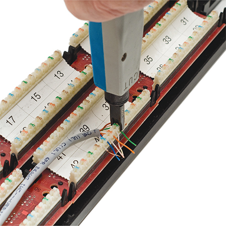
Figure 5-15 Punching down a 110 block
The punchdown block has small metal-lined grooves for the individual wires. The punchdown tool has a blunt end that forces the wire into the groove. The metal in the groove slices the cladding enough to make contact.
NOTE Make sure you insert the wires according to the same standard (TIA/EIA 568A or TIA/EIA 568B) on both ends of the cable. If you don’t, you might end up swapping the sending and receiving wires (known as transmit and receive TX/RX reversed) and inadvertently creating a crossover cable.
At one time, the older 66-punchdown block patch panel (a 66 block), found in just about every commercial telephone installation (Figure 5-16), saw some use in PC networks. The 110 block introduces less crosstalk than 66 blocks, so most high-speed network installations use the former for both telephone service and LANs. Given their large installed base, it’s still common to find a group of 66-block patch panels in a telecommunications room separate from the network’s 110-block patch panels.

Figure 5-16 66-block patch panels
Not only do patch panels prevent the horizontal cabling from being moved, but they are also your first line of defense in organizing the cables. All patch panels have space in the front for labels, and these labels are the network tech’s best friend! Simply place a tiny label on the patch panel to identify each cable, and you will never have to experience that sinking feeling of standing in the telecommunications room of your nonfunctioning network, wondering which cable is which. If you want to be a purist, there is an official, and rather confusing, ANSI/TIA naming convention called ANSI/TIA-606-C, but a number of real-world network techs simply use their own internal codes (Figure 5-17).

Figure 5-17 Typical patch panels with labels
Patch panels are available in a wide variety of configurations that include different types of ports and numbers of ports. You can get UTP, STP, or fiber ports, and some manufacturers combine several different types on the same patch panel. Panels are available with 8, 12, 24, 48, or even more ports.
UTP patch panels, like UTP cables, come with Cat ratings, which you should be sure to check. Don’t blow a good Cat 6 cable installation by buying a cheap patch panel—get a Cat 6 patch panel! A Cat 6 panel can handle the 250-MHz frequency used by Cat 6 and offers lower crosstalk and network interference. A higher-rated panel supports earlier standards, so you can use a Cat 6 or even Cat 6a rack with Cat 5e cabling. Most manufacturers proudly display the Cat level right on the patch panel (Figure 5-18).

Figure 5-18 Cat level on patch panel
Once you have installed the patch panel, you need to connect the ports to the switch through patch cables. Patch cables are short straight-through UTP cables. Patch cables use stranded core rather than solid core cable, so they can tolerate much more handling. Even though you can make your own patch cables, most people buy premade ones. Buying patch cables enables you to use different-colored cables to facilitate organization (yellow for accounting, blue for sales, or whatever scheme works for you). Most prefabricated patch cables also come with a reinforced (booted) connector specially designed to handle multiple insertions and removals (Figure 5-19).

Figure 5-19 Typical patch cable
Alternative Cable Connection Points Although you’ll most likely encounter 110 blocks today, some cable installations—especially outside the United States—incorporate proprietary cable interconnects. The BIX block, for example, is a proprietary networking interconnect developed by Nortel Networks. (BIX stands for Building Industry Cross-connect, in case you’re curious.) Similar in function to a 110-punchdown block, a BIX block is installed on a wall rather than in a rack. Figure 5-20 shows BIX blocks and connectors.

Figure 5-20 BIX blocks and connectors
The Krone LSA-PLUS proprietary European telecommunication connector—Krone block—offers another alternative to the 110-punchdown block. Developed by the German telecommunications company The Krone Group in the 1970s, Krone connectors enable networking as well as audio interconnections. Figure 5-21 shows a couple of Krone blocks.

Figure 5-21 Krone blocks
EXAM TIP Networks that include audio/video components (like with the Total Seminars video production studio, where I make awesome training videos for you) have a second set of wires for the A/V connections running to the telecommunications room. These runs of coaxial or fiber connect to a patch bay, a dedicated block with A/V connections rather than twisted pair and fiber network connections. Expect a question on the CompTIA Network+ exam that explores patch bays.
Finishing the Telecommunications Room Portion A telecommunications room doesn’t have to be a special room dedicated to computer equipment. You can use specially made cabinets with their own little built-in equipment racks that sit on the floor or attach to a wall, or you can use a storage room if the equipment can be protected from the other items stored there. Fortunately, the demand for telecommunications rooms has been around for so long that most office spaces have premade telecommunications rooms, even if they are no more than closets in smaller offices.
At this point, the network is taking shape (Figure 5-22). The horizontal cabling is installed, and the telecommunications room is configured. Now it’s time to address the last part of the structured cabling system: the work area.

Figure 5-22 Network taking shape, with racks installed and horizontal cabling runs
The Work Area
From a cabling standpoint, a work area is nothing more than a wall outlet that serves as the termination point for horizontal network cables: a convenient insertion point for a PC and a telephone. (In practice, of course, the term “work area” includes the office or cubicle.) A wall outlet itself consists of one or two female jacks to accept the cable, a mounting bracket, and a faceplate. You connect the PC to the wall outlet with a patch cable (Figure 5-23).

Figure 5-23 Typical work area outlet
The female RJ-45 jacks in these wall outlets also have Cat ratings. You must buy Cat-rated jacks for wall outlets to go along with the Cat rating of the cabling in your network. In fact, many network connector manufacturers use the same connectors in the wall outlets that they use on the patch panels. These modular outlets significantly increase ease of installation. Make sure you label the outlet to show the job of each connector (Figure 5-24). A good outlet will also have some form of label that identifies its position on the patch panel. Proper documentation of your outlets will save you an incredible amount of work later.
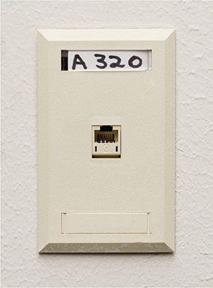
Figure 5-24 Properly labeled outlet
The last step is connecting the PC to the wall outlet. Here again, most folks use a patch cable. Its stranded core cabling stands up to the abuse caused by moving PCs, not to mention the occasional kick.
You’ll recall from Chapter 4 that most Ethernet networks specify a limit of 100 meters between a switch and a node. Interestingly, though, the TIA/EIA 568 specification allows only UTP cable lengths of 90 meters. What’s with the missing 10 meters? Have you figured it out? Hint: The answer lies in the discussion we’ve just been having. Ding! Time’s up! The answer is … the patch cables! Patch cables add extra distance between the switch and the PC, so TIA/EIA compensates by reducing the horizontal cabling length.
The work area may be the simplest part of the structured cabling system, but it is also the source of most network failures. When a user can’t access the network and you suspect a broken cable, the first place to look is the work area.
Structured Cable—Beyond the Star
Thus far you’ve seen structured cabling as a single star topology on a single floor of a building. Let’s now expand that concept to an entire building and learn the terms used by the structured cabling folks, such as the demarc and NIU, to describe this much more complex setup.
NOTE Structured cabling goes beyond a single building and even describes methods for interconnecting multiple buildings. The CompTIA Network+ certification exam does not cover interbuilding connections.
You can hardly find a building today that isn’t connected to both the Internet and the telephone company. In many cases, this is a single connection, but for now, let’s treat them as separate connections.
As you saw in Chapter 4, a typical building-wide network consists of a high-speed backbone that runs vertically through the building and connects to multispeed switches on each floor that, in turn, service the individual PCs on that floor. A legacy telephone cabling backbone that enabled the distribution of phone calls to individual telephones might run alongside the network cabling. While every telephone installation varies, most commonly you’ll see one or more strands of 25-pair UTP cables running to a 66 block in the telecommunications room on each floor (Figure 5-25).
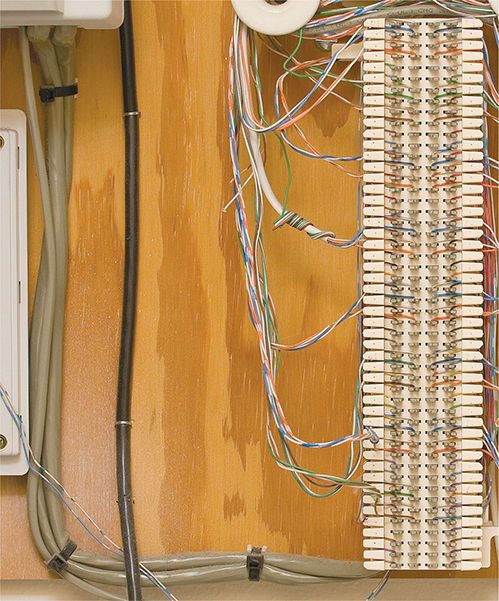
Figure 5-25 25-pair UTP cables running to local 66 block
Demarc
Connections from the outside world—whether network or telephone—come into a building at a location called a demarcation point (demarc). The demarc refers to the physical location of the connection and marks the dividing line of responsibility for the functioning of the network. You take care of the internal functioning; the company that supplies the upstream service to you must support connectivity and function on the far side of the demarc.
EXAM TIP You might get a question about the location of a demarc on the CompTIA Network+ exam. You’ll find the demarc located in the service-related entry point for a network.
The best way to think of a demarc is in terms of responsibility. If something breaks on one side of the demarc, it’s your problem; on the other side, it’s the ISP’s problem.
In a private home, the equipment (cable modem, optical network terminal, etc.) supplied by your ISP is a network interface unit (NIU) that serves as a demarc between your home network and your ISP, and most homes have a network interface box, like the one shown in Figure 5-26.

Figure 5-26 Typical home network interface box for home fiber Internet service
EXAM TIP One challenge to companies that supply Internet services is the need to diagnose faults in the system. Early systems used an NIU called a smartjack to set up a remote loopback—critical for loopback testing when you were at one end of the connection and the other connection was blocks or even miles away. Traditional smartjacks don’t exist, but CompTIA left them in the Network+ objectives. Go figure.
In an office environment, the demarc is usually more complex, given that a typical building simply has to serve a much larger number of computers. Figure 5-27 shows the demarc for a midsized building, showing both Internet and legacy telephone connections coming in from the outside.

Figure 5-27 Messy office demarcs for Internet and legacy phone
NOTE The terms used to describe the devices that often mark the demarcation point in a home or office get tossed about with wild abandon. Various manufacturers and technicians call them network interface units, network interface boxes, or network interface devices. (Some techs call them demarcs, just to muddy the waters further, but we won’t go there.) By name or by initial—NIU, NIB, or NID—it’s all the same thing, the box that marks the point where your responsibility begins.
Connections Inside the Demarc
After the demarc, network and telephone cables connect to some type of box, owned by the customer, that acts as the primary distribution tool for the building. That box is called the customer-premises equipment (CPE). Any cabling that runs from the NIU to whatever CPE is used by the customer is the demarc extension. The cabling connects to a powerful switch or other network box (that we’ll cover in detail in later chapters). This switch usually connects to a patch panel. This patch panel, in turn, leads to every telecommunications room in the building. This main patch panel is called a vertical cross-connect. Figure 5-28 shows an example of a fiber distribution panel (fiber patch panel) acting as a vertical cross-connect for a building.
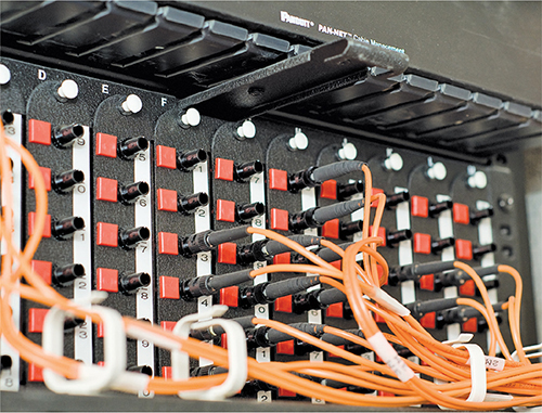
Figure 5-28 LAN vertical cross-connect
The combination of demarc and LAN cross-connects needs a place to live in a building. The room that stores all of this equipment is known as a main distribution frame (MDF) to distinguish it from the multiple IDF rooms (aka telecommunications rooms) that serve individual floors.
The ideal that every building should have a single demarc, a single MDF, and multiple IDFs is only that—an ideal. Every structured cabling installation is unique and must adapt to the physical constraints of the building provided. One building may serve multiple customers, creating the need for multiple NIUs each serving a different customer. A smaller building may combine a demarc, MDF, and IDF into a single room. With structured cabling, the idea is to appreciate the terms while, at the same time, appreciating that it’s the actual building and the needs of the customers that determine the design of a structured cabling system.
Installing Structured Cabling
A professional installer always begins a structured cabling installation by first assessing your site and planning the installation in detail before pulling a single piece of cable. As the customer, your job is to work closely with the installer. That means locating floor plans, providing access, and even putting on old clothes and crawling along with the installer as he or she combs through your ceilings, walls, and closets. Even though you’re not the actual installer, you must understand the installation process to help the installer make the right decisions for your network.
Structured cabling requires a lot of planning. You need to know if the cables from the work areas can reach the telecommunications room—is the distance less than the 90-meter limit dictated by the TIA/EIA standard? How will you route the cable? What path should each run take to get to the wall outlets? Don’t forget that just because a cable looks like it will reach, there’s no guarantee that it will. Ceilings and walls often include hidden surprises like firewalls—big, thick, concrete walls designed into buildings that require a masonry drill or a jackhammer to punch through. Let’s look at the steps that go into proper planning.
Getting a Floor Plan
First, you need a blueprint of the area. If you ever contact an installer who doesn’t start by asking for a floor plan, fire the installer immediately and get one who does. The floor plan is the key to proper planning; a good floor plan shows you the location of closets that could serve as telecommunications rooms, alerts you to any firewalls in your way, and gives you a good overall feel for the scope of the job ahead.
If you don’t have a floor plan—and this is often the case with homes or older buildings—you’ll need to create your own. Go get a ladder and a flashlight—you’ll need them to poke around in ceilings, closets, and crawl spaces as you map out the location of rooms, walls, and anything else of interest to the installation. Figure 5-29 shows a typical do-it-yourself floor plan.

Figure 5-29 Network floor plan
EXAM TIP A floor plan is a key component of organizational documents, part of the physical network diagram of an organization. You might see it as one of the correct options for important documentation on the CompTIA Network+ exam.
Mapping the Runs
Now that you have your floor plan, you need to map the cable runs. Here’s where you survey the work areas, noting the locations of existing or planned systems to determine where to place each cable drop. A cable drop is the location where the cable comes out of the wall in the work area. You should also talk to users, management, and other interested parties to try to understand their plans for the future. Installing a few extra drops now is much easier than installing them a year from now when those two unused offices suddenly find themselves with users who immediately need networked computers!
At this point, cost first raises its ugly head. Face it: cables, drops, and the people who install them cost money! The typical price for a network installation in Houston, Texas, for example, is around US $50–150 per drop. Cost will vary in different locales. Find out how much you want to spend and make some calls. Most network installers price their network jobs by quoting a per-drop cost.
EXAM TIP Watch out for the word drop, as it has more than one meaning. A single run of cable from the telecommunications room to a wall outlet is often referred to as a “drop.” The word “drop” is also used to define a new run coming through a wall outlet that does not yet have a jack installed.
While you’re mapping your runs, you have to make another big decision: Do you want to run the cables in the walls or outside them? Many companies sell wonderful external raceway products that adhere to your walls, making for a much simpler, though less neat, installation than running cables in the walls (Figure 5-30). Raceways make good sense in older buildings or when you don’t have the guts—or the rights—to go into the walls.

Figure 5-30 A typical raceway
Determining the Location of the Telecommunications Room
While mapping the runs, you should decide on the location of your telecommunications room. When deciding on this location, keep five issues in mind:
• Distance The telecommunications room must be located in a spot that won’t require cable runs longer than 90 meters. In most locations, keeping runs under 90 meters requires little effort, as long as the telecommunications room is placed in a central location.
• Power Many of the components in your telecommunications room need power. Make sure you provide enough! If possible, put the telecommunications room on its own dedicated circuit; that way, when someone blows a circuit in the kitchen, it doesn’t take out the entire network.
• Humidity Electrical components and water don’t mix well. (Remind me to tell you about the time I installed a rack in an abandoned bathroom and the toilet that later exploded.) Remember that dryness also means low humidity. Avoid areas with the potential for high humidity, such as a closet near a pool or the room where the cleaning people leave mop buckets full of water. Of course, any well air-conditioned room should be fine—which leads to the next big issue…
• Cooling Telecommunications rooms tend to get warm, especially if you add a couple of server systems and a UPS. Make sure your telecommunications room has an air-conditioning outlet or some other method of keeping the room cool. Figure 5-31 shows how I monitor the temp of my equipment rack.
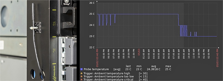
Figure 5-31 Temperature probe (left) with a graph of the temperature (right)
• Access Access involves two different issues. First, it means preventing unauthorized access. Think about the people you want and don’t want messing around with your network, and act accordingly. In my small office, the equipment closet literally sits eight feet from me, so I don’t concern myself too much with unauthorized access. You, on the other hand, may want to consider placing a lock on the door of your telecommunications room if you’re concerned that unscrupulous or unqualified people might try to access it.
One other issue to keep in mind when choosing your telecommunications room is expandability. Will this telecommunications room be able to grow with your network? Is it close enough to be able to service any additional office space your company may acquire nearby? If your company decides to take over the floor above you, can you easily run vertical cabling to another telecommunications room on that floor from this room? While the specific issues will be unique to each installation, keep thinking “expansion” or scalability as you design—your network will grow, whether or not you think so now!
So, you’ve mapped your cable runs and established your telecommunications room—now you’re ready to start pulling cable!
Pulling Cable
Pulling cable is easily one of the most thankless and unpleasant jobs in the entire networking world. It may not look that hard from a distance, but the devil is in the details. First of all, pulling cable requires two people if you want to get the job done quickly; having three people is even better. Most pullers like to start from the telecommunications room and pull toward the drops. In an office area with a drop ceiling, pullers often feed the cabling along the run by opening ceiling tiles and stringing the cable via hooks or cable trays that travel above the ceiling (Figure 5-32). Professional cable pullers have an arsenal of interesting tools to help them move the cable horizontally, including telescoping poles, coiled flat steel wire (called fish tape) for snaking through conduit, special nylon pull ropes, and even nifty little crossbows and pistols that can fire a pull rope long distances!
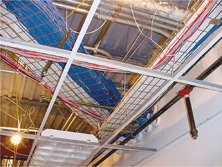
Figure 5-32 Cable trays over a drop ceiling
Cable trays are standard today, but a previous lack of codes or standards for handling cables led to a nightmare of disorganized cables in drop ceilings all over the world. Any cable puller will tell you that the hardest part of installing cables is the need to work around all the old cable installations in the ceiling (Figure 5-33).
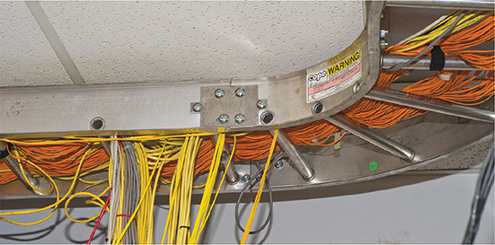
Figure 5-33 Messy cabling nightmare
Local codes, TIA, and the National Electrical Code (NEC) all have strict rules about how you pull cable in a ceiling. A good installer uses either hooks or trays, which provide better cable management, safety, and protection from electrical interference. The faster the network, the more critical good cable management (Figure 5-34) becomes.

Figure 5-34 Nicely run cables
Running cable horizontally requires relatively little effort, compared to running the cable down from the ceiling to a pretty faceplate at the work area, which often takes a lot of skill. In a typical office area with sheetrock walls, the installer first decides on the position for the outlet, generally using a stud finder to avoid cutting on top of a stud. Once the worker cuts the hole (Figure 5-35), most installers drop a line to the hole using a weight tied to the end of a nylon pull rope (Figure 5-36). They can then attach the network cable to the pull rope and pull it down to the hole. Once the cable is pulled through the new hole, the installer puts in an outlet box or a low-voltage mounting bracket (Figure 5-37). This bracket acts as a holder for the faceplate.

Figure 5-35 Cutting a hole

Figure 5-36 Locating a dropped pull rope

Figure 5-37 Installing a mounting bracket
Back in the telecommunications room, the many cables leading to each work area are consolidated and organized in preparation for the next stage: making connections. A truly professional installer takes great care in organizing the equipment closet. Figure 5-38 shows a typical installation using special cable guides to bring the cables down to the equipment rack.

Figure 5-38 End of cables guided to rack
Making Connections
Making connections consists of connecting both ends of each cable to the proper jacks. This step also includes the most important step in the entire process: testing each cable run to ensure that every connection meets the requirements of the network that will use it. Installers also use this step to document and label each cable run—a critical step too often forgotten by inexperienced installers, and one you need to verify takes place!
Connecting the Work Areas
In the work area, the cable installer terminates a cable run by adding a jack to the end of the wire and mounting the faceplate to complete the installation (Figure 5-39). Note the back of the jack shown in Figure 5-39. This jack uses the popular 110-punchdown connection just like the one shown earlier in the chapter for patch panels. All 110-punchdown connections have a color code that tells you which wire to punch into which connection on the back of the jack.

Figure 5-39 Punching down a jack
Rolling Your Own Patch Cables
Although most people prefer simply to purchase premade patch cables, making your own is fairly easy. To make your own, use stranded core UTP cable that matches the Cat level of your horizontal cabling. Stranded core cable also requires specific crimps, so don’t use crimps designed for solid core cable. Crimping is simple enough, although getting it right takes some practice.
Figure 5-40 shows the two main tools of the crimping trade: an RJ-45 crimper with built-in cable stripper and a pair of wire snips/cutters. Professional cable installers naturally have a wide variety of other tools as well.
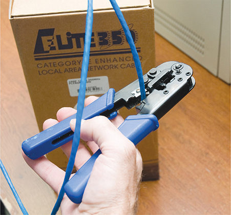
Figure 5-40 Crimper and snips/cutters
Here are the steps for properly crimping an RJ-45 onto a UTP cable. If you have some crimps, cable, and a crimping tool handy, follow along!
1. Cut the cable square using RJ-45 crimpers or scissors.
2. Strip at least ½ inch of plastic jacket from the end of the cable (Figure 5-41) with a dedicated cable stripper or the one built into the crimping tool.
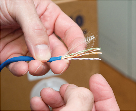
Figure 5-41 Properly stripped cable—it doesn’t hurt to leave room for mistakes!
3. Slowly and carefully insert each individual wire into the correct location according to either T568A or T568B (Figure 5-42). Unravel as little as possible.
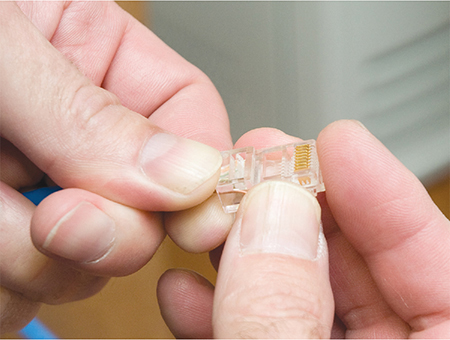
Figure 5-42 Inserting the individual strands
4. Insert the crimp into the crimper and press (Figure 5-43). Don’t worry about pressing too hard; the crimper has a stop to prevent you from using too much pressure.

Figure 5-43 Crimping the cable
Figure 5-44 shows a nicely crimped cable. Note how the plastic jacket goes into the crimp.

Figure 5-44 Properly crimped cable
A good patch cable should include a boot. Figure 5-45 shows a boot being slid onto a newly crimped cable. Don’t forget to slide each boot onto the patch cable before you crimp both ends!
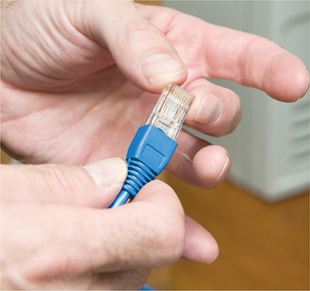
Figure 5-45 Adding a boot
After making a cable, you need to test it to make sure it’s properly crimped. Read the section on testing cable runs later in this chapter to see how to test them.
Try This!
Connecting the Patch Panels
Connecting the cables to patch panels requires you to deal with three issues. The first issue is patch cable management. Figure 5-46 shows the front of a small network’s equipment rack—note the complete lack of cable management!

Figure 5-46 Bad cable management
Managing patch cables means using the proper cable management hardware. Plastic D-rings guide the patch cables neatly along the sides and front of the patch panel. Finger boxes are rectangular cylinders with slots in the front; the patch cables run into the open ends of the box, and individual cables are threaded through the fingers on their way to the patch panel, keeping them neatly organized.
Creativity and variety abound in the world of cable-management hardware—there are as many different solutions to cable management as there are ways to screw it up. Figure 5-47 shows a rack using good cable management—these patch cables are well secured using cable-management hardware, making them much less susceptible to damage from mishandling. Plus, it looks much nicer!

Figure 5-47 Good cable management
The second issue to consider when connecting cables is the overall organization of the patch panel as it relates to the organization of your network. Organize your patch panel so it mirrors the layout of your network. You can organize according to the physical layout, so the different parts of the patch panel correspond to different parts of your office space—for example, the north and south sides of the hallway. Another popular way to organize patch panels is to make sure they match the logical layout of the network, so the different user groups or company organizations have their own sections of the patch panel.
Finally, proper patch panel cable management means documenting everything clearly and carefully. This way, any competent technician can follow behind you and troubleshoot connectivity problems. Good techs draw diagrams!
Testing the Cable Runs
Well, in theory, your horizontal cabling system is now installed and ready for a switch and some systems. Before you do this, though, you must test each cable run. Someone new to testing cable might think that all you need to do is verify that each jack has been properly connected. Although this is an important and necessary step, the interesting problem comes after that: verifying that your cable run can handle the speed of your network.
The basic Layer 1 issues with network connections boil down to three factors: signal degradation, lack of connection, and interference. A host of factors can cause overall degradation, which in turn slows or stops network communication. A lack of connection can be caused by many things, detailed below, but the effect is that the networked device(s) can’t communicate. Interference means any disruption on a medium (wired or wireless) that intentionally or inadvertently prevents valid signals from being read by an intended recipient.
Copper- and fiber-based network runs have different causes for loss of connectivity, interference, and degradation, and thus require different tools to resolve. Let’s look at copper, then fiber.
Before I go further, let me be clear: a typical network admin/tech cannot properly test a new cable run. TIA provides a series of incredibly complex and important standards for testing cable, requiring a professional cable installer. The testing equipment alone totally surpasses the cost of most smaller network installations. Advanced network testing tools easily cost over $5000, and some are well over $10,000! Never fear, though—a number of lower-end tools work just fine for basic network testing.
NOTE The test tools described here also enable you to diagnose network problems.
Copper Challenges
Most network admins staring at a scenario with a potentially bad copper cable want to know the following:
• How long is this cable? If it’s too long, the signal will degrade to the point that it’s no longer detectable on the other end.
• Every signal—copper, fiber, and wireless—has noise. Too much noise and the signal will degrade, the network will slow down or even stop. You’ll see this in action with cable Internet connections, so we’ll pick it up in Chapter 13.
• Are any of the wires broken or not connected in the crimp (open)? If a wire is broken or a connection is open, it no longer has continuity (a complete, functioning connection). Are there bent pins on the RJ-45 or in the jack?
• Is there any place where two bare wires touch? This creates a short. Shorts can take place when cables are damaged, but you can also get a short when improperly crimping two cables into the same place on a crimp.
EXAM TIP The CompTIA Network+ objectives lump open/short together as a common issue with cable connectivity. They’re different problems, as noted here, but have the same effect, which is no connectivity.
• If there is a break, where is it? It’s much easier to fix if the location is detectable.
• Are all of the wires terminated in the right place in the plug or jack? Does each termination match to the same standard? In other words, am I looking at an incorrect pinout scenario?
• Is there electrical or radio interference from outside sources? UTP is susceptible to electromagnetic interference (EMI), as introduced in Chapter 4.
• Is the signal from any of the pairs in the same cable interfering with another pair? This common problem in UTP installations is called a split pair.
To answer these questions, you must verify that both the cable and the terminated ends are correct. Making these verifications requires a cable tester. Various models of cable testers can answer some or all of these questions, depending on the amount of money you are willing to pay. At the low end of the cable tester market are devices that only test for continuity. These inexpensive (under $100) testers are often called continuity testers (Figure 5-48). Many of these testers require you to insert both ends of the cable into the tester. Of course, this can be a bit of a problem if the cable is already installed in the wall!
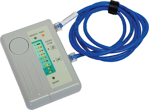
Figure 5-48 Continuity tester
Better testers can run a wire map test that goes beyond mere continuity, testing that all the wires on both ends of the cable connect to the right spot. A wire map test will pick up shorts, crossed wires, and more. Figure 5-49 shows a MicroScanner diagnosing a wire map problem.

Figure 5-49 MicroScanner readout
To check continuity, you can also use a multimeter, a device to test AC and DC voltage and current as well as continuity and resistance. Some advanced models can test other components such as transistors and capacitors. Set the multimeter (Figure 5-50) to continuity mode (if it has one) or to the lowest Ohm range on the device. In the latter mode, zero Ohms indicate continuity and infinite Ohms indicate no connection.

Figure 5-50 Multimeter
NOTE Many techs and network testing folks use the term wire map to refer to the proper connectivity for wires, as in, “Hey Joe, check the wire map!”
Medium-priced testers (~$400) certainly test continuity and wire map and include the additional capability to determine the length of a cable; they can even tell you where a break is located on any of the individual wire strands. This type of cable tester (Figure 5-51) is generically called a time-domain reflectometer (TDR). Most medium-priced testers come with a small loopback device to insert into the far end of the cable, enabling the tester to work with installed cables. This is the type of tester you want to have around!

Figure 5-51 A vintage MicroScanner TDR
If you want a device that fully tests a cable run to the very complex TIA standards, the price shoots up fast. These higher-end testers can detect things the lesser testers cannot, such as crosstalk and attenuation.
Crosstalk poses a threat to properly functioning cable runs. Today’s UTP cables consist of four pairs of wires, all squished together inside a plastic tube. When you send a signal down one of these pairs, the other pairs pick up some of the signal, as shown in Figure 5-52. This is called crosstalk.

Figure 5-52 Crosstalk
Every piece of UTP in existence generates crosstalk. Worse, when you crimp the end of a UTP cable to a jack or plugs, crosstalk increases. A poor-quality crimp creates so much crosstalk that a cable run won’t operate at its designed speed. To detect crosstalk, a normal-strength signal is sent down one pair of wires in a cable. An electronic detector, connected on the same end of the cable as the end emanating the signal, listens on the other three pairs and measures the amount of interference, as shown in Figure 5-53. This is called near-end crosstalk (NEXT).

Figure 5-53 Near-end crosstalk
If you repeat this test, sending the signal down one pair of wires, but this time listening on the other pairs on the far end of the connection, you test for far-end crosstalk (FEXT), as shown in Figure 5-54.
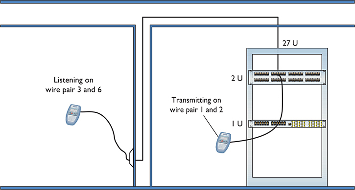
Figure 5-54 Far-end crosstalk
NOTE Both NEXT and FEXT are measured in decibels (dB).
If that’s not bad enough, as a signal progresses down a piece of wire, it becomes steadily weaker; this is called attenuation. As a cable run gets longer, the attenuation increases, and the signal becomes more susceptible to crosstalk. A tester must send a signal down one end of a wire, test for NEXT and FEXT on the ends of every other pair, and then repeat this process for every pair in the UTP cable.
EXAM TIP Every network—copper or otherwise—experiences data loss or lag over distances and with enough traffic. Ethernet network frame traffic has latency, a delay between the time the sending machine sends a message and the time the receiving machine can start processing those frames.
Add in a lot of machines and the network will also experience jitter, a delay in completing a transmission of all the frames in a message. This is perfectly normal and modern network technologies handle jitter fine. This does not affect moving files around much, but becomes a serious problem in real-time voice communication. Excessive jitter generally sounds like, “Dude, you’re totally breaking up.” We’ll explore voice communication in Chapter 17 in some detail.
This process of verifying that every cable run meets the exacting TIA standards requires very powerful testing tools, generally known as cable certifiers or just certifiers. Cable certifiers can both do the high-end testing and generate a report that a cable installer can print out and hand to a customer to prove that the installed cable runs pass TIA standards. Cable certifiers cost a lot and are thus reserved for cable installation experts rather than network techs.
Measuring Signal Loss
Signal loss in networking is measured in a unit called a decibel (dB). This applies to both electrical signals in copper wires and light signals in fiber cables. Unfortunately for a lot of network techs, a decibel is tough to grasp without a lot of math. I’m going to skip the technical details and give you a shorthand way to understand the numbers to troubleshoot a cable connectivity scenario with decibel (dB) loss.
When referring to a signal traveling from one end of a cable to another, you really care about how much information on that signal gets to the end, right? In a simple sense, if you have some interference, some imperfections in the cable or fiber, you’ll get some loss from beginning to end. Most people think about that loss in terms of percentage or even in more common terms, like “a little” or “a lot of” loss. No problem, right?
The problem when you take that same concept to networking is that the percentages lost can be gigantic or really, really small. When you start talking about a 10,000% loss or a .00001% loss, most folks’ eyes glaze over. The numbers are simply too big or small to make intuitive sense.
Technicians use the term decibel to describe those numbers in a more digestible format. When a tech looks at a signal loss of 3 dB, for example, he or she should be able to know that that number is a lot smaller than a signal loss of 10 dB.
Fiber Challenges
Fiber cable runs offer similar challenges to copper cable runs, but there are also some very specific differences. Just like with copper, signal loss is important and measured in decibels. But the causes of loss can differ a lot. Also, the many competing standards can catch techs running fiber by surprise.
Signal Loss/Degradation Just like with copper wire, various imperfections in the media—the glass fiber, in this case—cause signal loss over distance. A lot of factors come into play.
Damaged cables or open connections obviously stop signals. The typical small form-factor pluggable (SFP) or gigabit interface converter (GBIC) can have problems. When you’re checking for a bad SFP/GBIC, you’ll need to check both the connector and the cable going into that connector. Either or both could cause the signal loss.
A dirty connector—CompTIA calls these dirty optical cables—can cause pretty serious signal loss with fiber. It’s important not to smudge the glass!
When you think about fiber-optic cables, you need to remember that the part that carries the signal is really tiny, only a few microns. When you’re connecting two pieces of fiber, even a small connector mismatch in either the cladding (the outside) or the core (the inside) can cause serious losses.
Attenuation is the weakening of a signal as it travels long distances, as you’ll recall from earlier in the chapter.
Dispersion is when a signal spreads out over long distances. Both attenuation and dispersion are caused when wave signals travel too far without help over fiber-optic media. This is also called modal dispersion.
Every piece of fiber has a certain bend radius limitation. If you bend a fiber-optic cable too much, you get light leakage, as shown in Figure 5-55. Light leakage means that part of the signal goes out the cable rather than arriving at the end. That’s not a good thing.

Figure 5-55 Light leakage—the arrows indicate light leaking out at the bends.
Physical or Signal Mismatch Fiber networks have a relatively small number of connectors but offer a pretty wide variety of signal types that use those connectors. These variations come into play in several ways. First, just because you can connect to a particular SFP or GBIC, that doesn’t mean the signal will work. Plugging an incorrect transceiver into a Cisco switch might work in a physical sense, but if the switch won’t play with anything but Cisco technology, you’ll get a transceiver mismatch.
Likewise, you can find fiber connectors like SC or LC that will attach to single-mode or multimode fiber. Plugging a single-mode cable into a switch that expects multimode? Such a cable mismatch or fiber mismatch—an incorrect cable type—means your network—at least that portion of it—won’t work.
Finally, different runs of fiber use different wavelength signals. You might be able to plug an LC connector into a switch just fine, for example, but if the signal starts at 1310 nm and the switch expects 1530 nm, that sort of wavelength mismatch will stop the transmission cold.
Fiber Tools A fiber technician uses a large number of tools (Figure 5-56) and an almost artistic amount of skill. Over the years, easier terminations have been developed, but putting an ST, SC, LC, or other connector on the end of a piece of fiber is still very challenging.
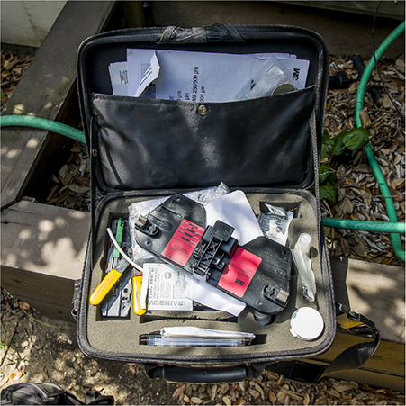
Figure 5-56 Fiber splicing kit in the field
A fiber-optic run has problems that are both similar to and different from those of a UTP run. Fiber-optic runs don’t experience crosstalk or interference (as we usually think of it) because they use light instead of an electrical current.
Fiber-optic cables still break, however, so a good tech always keeps an optical time-domain reflectometer (OTDR) handy (Figure 5-57) for just such scenarios. OTDRs determine continuity and, if there’s a break, tell you exactly how far down the cable to look for the break.

Figure 5-57 An optical time-domain reflectometer (photo courtesy of Fluke Networks)
TIA has very complex requirements for testing fiber runs, and the cabling industry sells fiber certifiers to make sure a fiber will carry its designed signal speed.
EXAM TIP One of the common tools for fiber-optic cable installers is a fusion splicer that enables the tech to combine two fiber-optic cables without losing quality.
The three big issues with fiber are light leakage, attenuation, and dispersion. You read about all three earlier in the chapter.
The process of installing a structured cabling system is rather involved, requires a great degree of skill, and should be left to professionals. By understanding the process, however, you can tackle most of the problems that come up in an installed structured cabling system. Most importantly, you’ll understand the lingo used by the structured cabling installers so you can work with them more efficiently.
NICs
Now that the network is completely in place, it’s time to turn to the final part of any physical network: the NICs. A good network tech must recognize different types of NICs by sight and know how to install and troubleshoot them. Let’s begin by reviewing the differences between UTP and fiber-optic NICs.
All UTP Ethernet NICs use the RJ-45 connector. The cable runs from the NIC (Figure 5-58) to a switch.
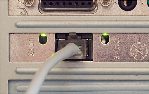
Figure 5-58 Typical UTP NIC
NOTE Motherboards these days include an onboard NIC. This, of course, completely destroys the use of the acronym “NIC” to represent network interface card because no card is actually involved. But heck, we’re nerds and, just as we’ll probably never stop using the term “RJ-45” when the correct term is “8P8C,” we’ll keep using the term “NIC.” I know! Let’s just pretend it stands for network interface connection!
Fiber-optic NICs come in a wide variety and can support multiple standards. Figure 5-59 shows a typical fiber-optic network card.

Figure 5-59 Typical NIC supporting fiber (Copyright © Intel Corporation)
Buying NICs
Some folks may disagree with me, but I always purchase name-brand NICs. For NICs, I recommend sticking with big names, such as Intel. The NICs are better made, have extra features, and are easy to return if they turn out to be defective.
Plus, replacing a missing driver on a name-brand NIC is easy, and you can be confident the drivers work well. The type of NIC you should purchase depends on your network. Try to stick with the same model of NIC. Every different model you buy means another set of drivers. Using the same model of NIC makes driver updates easier, too.
Physical Connections
I’ll state the obvious here: If you don’t plug the NIC into the computer, the NIC won’t work! If you’re buying a NIC, physically inserting the NIC into one of the PC’s expansion slots is the easiest part of the job. Most PCs today have two types of expansion slots. The older expansion slot is the Peripheral Component Interconnect (PCI) type (Figure 5-60).
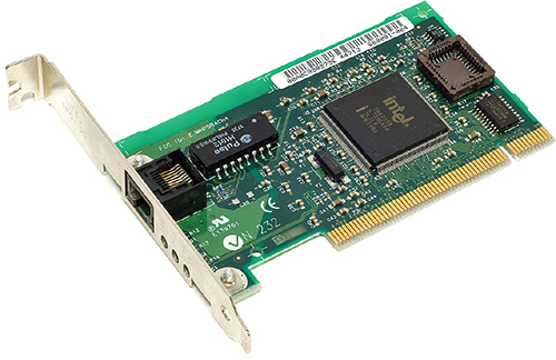
Figure 5-60 PCI NIC
The PCI Express (PCIe) expansion slots are now widely adopted by NIC suppliers. PCIe NICs usually come in either one-lane (×1) or two-lane (×2) varieties (Figure 5-61). You would add a NIC if you wanted to connect a PC to a fiber-based network, for example, and only had onboard copper-based NIC.

Figure 5-61 PCIe NIC
If you’re not willing to open a PC case, you can get NICs with USB connections (Figure 5-62). USB NICs are handy to keep in your toolkit. If you walk up to a machine that might have a bad NIC, test your suspicions by inserting a USB NIC and moving the network cable from the potentially bad NIC to the USB one. (USB NICs are also commonly used with super-thin laptops that don’t come with built-in Ethernet ports.)

Figure 5-62 USB NIC
Drivers
A modern OS might have a driver included for the NIC. If not, installing a NIC’s driver into a Windows, macOS, or Linux system is easy: just insert a driver disc when prompted by the system. Many current systems don’t sport optical drives, so installing a new NIC requires access to the Internet. Have a spare machine and copy drivers to a USB flash drive, then install drivers from there.
Every operating system has some method to verify that the computer recognizes the NIC and is ready to use it. Windows systems have the Device Manager; Ubuntu Linux users have the Network applet under the Administration menu; and macOS users get the Network utility in System Preferences. Actually, most operating systems have multiple methods to show that the NIC is in good working order. Learn the various ways to verify the NIC for your OS, as this is the ultimate test of a good NIC installation.
Port Aggregation
Most switches enable you to use multiple NICs for a single machine, a process called port aggregation, bonding, or link aggregation. Bonding doesn’t necessarily increase the speed of the network connection, but instead adds another lane of equal speed. In cases where you’re sending multiple files over the network, bonding enables more than one file to copy or move at full speed. This effectively increases the overall bandwidth of the connection. If you want to add link aggregation to your network to increase performance, use identical NICs and switches from the same companies to avoid incompatibility.
EXAM TIP The Link Aggregation Control Protocol (LACP) controls how multiple network devices send and receive data as a single connection.
Link Lights
All NICs and switches made today have some type of light-emitting diodes (LEDs) that give information about the state of the link to whatever is on the other end of the connection. Even though you know the lights are actually LEDs, get used to calling them link lights, as that’s the term all network techs use. NICs and switches can have between one and four different link lights, and the LEDs can be any color. These lights give you clues about what’s happening with the link and are one of the first items to check whenever you think a system is disconnected from the network (Figure 5-63).

Figure 5-63 Switch with link lights off for port 7 and on for ports 1, 3, 5, and 9
EXAM TIP The CompTIA Network+ objectives call link lights light-emitting diode (LED) status indicators, so don’t miss that on the exam. In the real world, call them link lights.
A link light displays connectivity. If a PC can’t access a network and is acting disconnected, always check the link lights first. Multispeed devices usually have a link light that tells you the speed of the connection. In Figure 5-64, the left link light for port 2 is lit, but the right link light is not, signifying that the other end of the cable is plugged into a 100BASE-T NIC. Port 1, on the other hand, has both link lights lit. It’s clearly Gigabit.
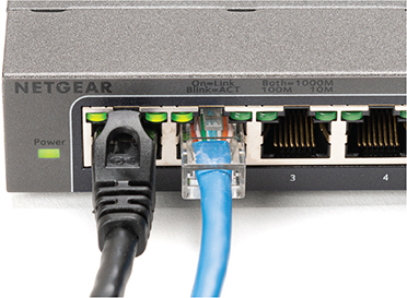
Figure 5-64 Multispeed lights
Another light is the activity light. This little guy turns on when the card detects network traffic, so it intermittently flickers when operating properly. The activity light is a lifesaver for detecting problems, because in the real world, the connection light will sometimes lie to you. If the connection light says the connection is good, the next step is to try to copy a file or do something else to create network traffic. If the activity light does not flicker, there’s a problem.
On many NICs, a properly functioning link light is on and steady when the NIC is connected to another device. On with no flickering indicates a good connection. On NICs that use a single LED to display both the link and activity status, on the other hand, the single LED will flicker with activity. That’s how the NIC in Figure 5-63 works. Read the online documentation from the NIC manufacturer’s Web site to determine the meaning of the lights and their steadiness or flickering.
No standard governs how NIC or switch manufacturers use their lights, and, as a result, they come in an amazing array of colors and layouts. When you encounter a NIC or switch with a number of LEDs, take a moment to try to figure out what each one means. Although different NICs and switches have various ways of arranging and using their LEDs, the functions are always the same: link, activity, and speed.
Diagnostics and Repair of Physical Cabling
“The network’s down!” is easily the most terrifying phrase a network tech will ever hear. Networks fail for many reasons, and the first thing to know is that good-quality, professionally installed cabling rarely goes bad. Chapter 20 covers principles of network diagnostics and support that apply to all networking scenarios, but let’s take a moment now to discuss how to troubleshoot common cable connectivity issues when faced with a scenario that points to a problem with your physical network.
Diagnosing Physical Problems
Look for errors that point to physical disconnection. A key clue that you may have a physical problem is that a user gets a “No server is found” error, or tries to use the operating system’s network explorer utility (like Network in Windows) and doesn’t see any systems besides his or her own. First, try to eliminate software errors: If one application fails, try another. If the user can’t browse the Internet, but can get e-mail, odds are good that the problem is with software, not hardware—unless someone unplugged the e-mail server!
Multiple systems failing to access the network often points to hardware problems. This is where knowledge of your network cabling helps. If all the systems connected to one switch suddenly no longer see the network, but all the other systems in your network still function, you not only have a probable hardware problem but also a suspect—the switch.
Check Your Lights
If you suspect a hardware problem, first check the link lights on the NIC and switch. If they’re not lit, you know the cable isn’t connected somewhere. If you’re not physically at the system in question (if you’re on a tech call, for example), you can have the user check his or her connection status through the link lights or through software. Every operating system has some way to tell you on the screen if it detects the NIC is disconnected. The network status icon in the notification area in Windows, for example, displays a stylized globe with a small “not connected” circle with a line through it when a NIC is disconnected (Figure 5-65), as opposed to a connected computer symbol when properly connected (Figure 5-66).

Figure 5-65 Disconnected NIC in Windows

Figure 5-66 Connected NIC in Windows
If a problem system has no connection, eliminate the possibility of a failed switch or other larger problem by checking to make sure other people can access the network, and that other systems can access the shared resource (server) that the problem system can’t see. Make a quick visual inspection of the cable running from the back of the PC to the outlet.
Finally, if you can, plug the system into a known-good outlet and see if it works. A good network tech always keeps a long patch cable for just this purpose. If you get connectivity with the second outlet, you should begin to suspect bad wiring in structured cable running from the first outlet to the switch. Or, it could be a bad connector. Assuming the cable is installed properly and has been working correctly before this event, a simple continuity test will confirm your suspicion in most cases.
Check the NIC
Be warned that a bad NIC can also generate this “can’t see the network” problem. Use the utility provided by your OS to verify that the NIC works. If you’ve got a NIC with diagnostic software, run it—this software checks the NIC’s circuitry. The NIC’s female connector is a common failure point, so NICs that come with diagnostic software often include a special test called a loopback test. A loopback test sends data out of the NIC and checks to see if it comes back. Some NICs perform only an internal loopback, which tests the circuitry that sends and receives, but not the actual connecting pins. A true external loopback requires a loopback adapter or loopback plug inserted into the NIC’s port (Figure 5-67). If a NIC is bad or has a bad port, replace it—preferably with an identical NIC so you don’t have to reinstall drivers!

Figure 5-67 Loopback adapter or plug
NOTE Onboard NICs on laptops are especially notorious for breaking due to constant plugging and unplugging. On some laptops, the NICs are easy to replace; others require a motherboard replacement.
Cable Testing
The vast majority of network disconnect problems occur at the work area. If you’ve tested those connections, though, and the work area seems fine, it’s time to consider deeper issues.
With the right equipment, diagnosing a bad horizontal cabling run is easy. Anyone with a network should own a midrange tester with TDR such as the Fluke MicroScanner. With a little practice, you can easily determine not only whether a cable is disconnected but also where the disconnection takes place. Sometimes patience is required, especially if the cable runs aren’t labeled, but you will find the problem.
When you’re testing a cable run, always include the patch cables as you test. This means unplugging the patch cable from the PC, attaching a tester, and then going to the telecommunications room. Here you’ll want to unplug the patch cable from the switch and plug the tester into that patch cable, making a complete test, as shown in Figure 5-68.

Figure 5-68 Loopback adapter in action
Testing in this manner gives you a complete test from the switch to the system. In general, a broken cable must be replaced. Fixing a bad patch cable is easy, but what happens if the horizontal cable is to blame? In these cases, I get on the phone and call my local installer. If a cable’s bad in one spot, the risk of it being bad in another is simply too great to try anything other than total replacement.
Finally, check the coupler if one is used to extend a cable run. Couplers are small devices with two female ports that enable you to connect two pieces of cable together to overcome distance limitations. UTP couplers are most common, but you can find couplers for every type of network: fiber couplers, even coaxial or BNC couplers. The plastic UTP couplers are relatively easily broken.
Problems in the Telecommunications Room
Even a well-organized telecommunications room is a complex maze of equipment racks, switches, and patch panels. The most important issue to remember as you work is to keep your diagnostic process organized and documented. For example, if you’re testing a series of cable runs along a patch panel, start at one end and don’t skip connections. Place a sticker as you work to keep track of where you are on the panel.
Your biggest concerns in the telecommunications room are facilities and infrastructure support concerns such as power and air quality.
All those boxes in the rack need good-quality power. Even the smallest rack should run off of a good uninterruptible power supply (UPS), a battery backup that plugs into the wall. Make sure you get one that can handle the amount of wattage used by all the equipment in the rack.
A UPS provides several benefits. First, it acts as an inverter. It stores power as direct current in its battery, then inverts that power to alternating current as the servers and other boxes in the rack system require. A good UPS acts as a power monitoring tool so it can report problems when there’s any fluctuation in the electrical supply. All UPS boxes can provide security from power spikes and sags.
A UPS enables you to shut down in an orderly fashion. It does not provide enough power for you to continue working. The device that handles the latter service is called a generator.
NOTE You can purchase two different types of UPSs—online and standby. An online UPS continuously charges a battery that, in turn, powers the computer components. If the telecommunications room loses power, the computers stay powered up without missing a beat, at least until the battery runs out.
A standby power supply (SPS) also has a big battery but doesn’t power the computer unless the power goes out. Circuitry detects the power outage and immediately kicks on the battery.
Pay attention to how often your UPS kicks in. Don’t assume the power coming from your physical plant (or power company) is okay. If your UPS comes on too often, it might be time to install a voltage event recorder (Figure 5-69). As its name implies, a voltage event recorder plugs into your power outlet and tracks the voltage over time. These devices often reveal interesting issues.

Figure 5-69 A voltage event recorder (photo courtesy of Fluke Networks)
The temperature in the telecommunications room should be maintained and monitored properly. If you lose the air conditioning, for example, and leave systems running, the equipment will overheat and shut down—sometimes with serious damage. To prevent this, all serious telecommunications rooms should have a UPS with a temperature monitor.
Likewise, you need to control the level of humidity in a telecommunications room. You can install environmental monitors that keep a constant watch on humidity, temperature, and more, for just a few hundred dollars. The devices cost little in comparison to the equipment in the telecommunications room that you’re protecting.
Toners
It would be nice to say that all cable installations are perfect and that over the years they won’t tend to grow into horrific piles of spaghetti-like, unlabeled cables. In the real world, though, you might eventually find yourself having to locate or trace cables. Even in the best-planned networks, labels fall off ports and outlets, mystery cables appear behind walls, new cable runs are added, and mistakes are made counting rows and columns on patch panels. Sooner or later, most network techs will have to be able to pick out one particular cable or port from a stack.
When the time comes to trace cables, network techs turn to a device called a toner for help. Toner is the generic term for two separate devices that are used together: a tone generator and a tone probe. The tone generator connects to the cable using alligator clips, tiny hooks, or a network jack, and it sends an electrical signal along the wire at a certain frequency. The tone probe emits a sound when it is placed near a cable connected to the tone generator. These two devices are often referred to by the brand-name Fox and Hound (Figure 5-70), a popular model of toner made by the Triplett Corporation.

Figure 5-70 Fox and Hound
To trace a cable, connect the tone generator to the known end of the cable in question, and then position the tone probe next to the other end of each of the cables that might be the right one. The tone probe makes a sound when it’s placed next to the right cable. Some toners have one tone probe that works with multiple tone generators. Each generator emits a separate frequency, and the probe sounds a different tone for each one. Even good toners are relatively inexpensive ($75); although inexpensive toners can cost less than $25, they don’t tend to work well, so spending a little more is worthwhile. Just keep in mind that if you have to support a network, you’d do best to own a decent toner.
A good, medium-priced cable tester and a good toner are the most important tools for folks who must support, but not install, networks. A final tip: Be sure to bring along a few extra batteries—there’s nothing worse than sitting on the top of a ladder holding a cable tester or toner that has just run out of juice!
Chapter Review
Questions
1. Aside from outright breakage, what’s the primary worry with bending a fiber-optic cable too much?
A. Attenuation
B. Bonding
C. Light leakage
D. Near-end crosstalk
2. Which of the following enables you to use multiple NICs in a computer to achieve a much better network bandwidth?
A. Linking
B. Port aggregation
C. SLI
D. Xing
3. How many pairs of wires are in a Cat 6-rated cable?
A. 2
B. 4
C. 8
D. It doesn’t specify.
4. A(n) _______________ organizes and protects the horizontal cabling in the telecommunications room.
A. rack
B. patch panel
C. outlet
D. 110 jack
5. Which of the following would never be seen in an equipment rack?
A. Patch panel
B. UPS
C. PC
D. All of the above may be seen in an equipment rack.
6. What are patch cables used for? (Select two.)
A. To connect different telecommunications rooms.
B. To connect the patch panel to the switch.
C. They are used as crossover cables.
D. To connect PCs to outlet boxes.
7. Which of the following network technologies use UTP cabling in a star topology?
A. Crosstalk
B. Fiber optics
C. 1000BASE-SX
D. 1000BASE-T
8. Your first day on the job, you get a call from the owner complaining that her network connection is down. A quick check of the central switch verifies that it’s in good working order, as is the boss’s PC. As luck would have it, your supervisor calls at just that time and tells you not to worry; she’ll be by in a jiffy with her TDR to help root out the problem. What is she talking about?
A. Tune-domain resonator, her network tone generator
B. Time-detuning resonator, her network tester
C. Time-domain reflectometer, her network tester
D. Time-detail resource, her network schematic
9. What two devices together enable you to pick a single cable out of a stack of cables? (Select two.)
A. Tone aggregator
B. Tone binder
C. Tone generator
D. Tone probe
10. Rack-mounted equipment has a height measured in what units?
A. Mbps
B. MBps
C. Inches
D. U
Answers
1. C. Bending a fiber-optic cable too much can cause light leakage and thus loss or degradation of signal.
2. B. Port aggregation (or bonding or link aggregation) is the process of using multiple NICs as a single connection, thus increasing bandwidth.
3. B. The Cat 6 rating requires four pairs of wires.
4. B. A patch panel organizes and protects the horizontal cabling in the telecommunications room.
5. D. All these devices may be found in equipment racks.
6. B and D. Patch cables are used to connect the patch panel to the switch and the PCs to the outlet boxes.
7. D. 1000BASE-T uses UTP cabling in a star topology.
8. C. TDR stands for time-domain reflectometer, the generic term for a decent network tester that can determine locations of cable breaks, among other things.
9. C and D. A tone generator and tone probe work together to enable you to pick a single cable out of a stack of cables.
10. D. Rack-mounted equipment uses a height measurement known as a unit (U).