C.2 A Typical Linking Loader
We shall now describe in brief a typical linking loader.
C.2.1 Data from Object Modules
The information concerning linking operations is provided by the esd and rld records from object modules.
ESD
Provide the information necessary to build the External Symbols Dictionary or the symbol table. There are three types of external symbols:
Module Definition, MD Name of the module;
Local Definition, LD Label of a locally defined area;
External Reference, ER A symbol which is an MD or LD in exactly one place in some other module.
Each MD and ER is identified by an integer (ID) used for reference in an rld record.
RLD
Records have the following information:
- The location and size of each address constant that will change due to relocation or linking.
- The external symbol by which the address constant should be modified.
- Whether plus or minus operation is to be done.
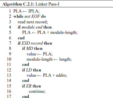
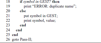
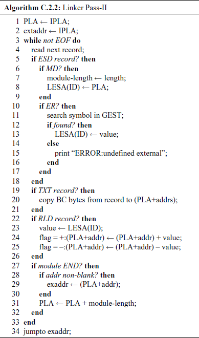
A linker operates in two phases – Pass-I and Pass-II.
C.2.2 Database Used or Created During Linking
IPLA Initial program load address – supplied by either the O/S or the programmer.
PLA Program load address – keeps track of each module's assigned location.
GEST Global external symbol table – stores each external symbol and its assigned address. This is prepared by Pass-I.
Load-map A listing showing each external symbol and its assigned value.
LESA Local external symbol array – used to establish a map between the ESD ID numbers and corresponding external symbol's address value.
C.2.3 Linker Algorithms