Component information system
Abstract
This chapter introduces component information system as a part management system that is available as an option for use with OrCAD Capture. It helps manage part properties, including part properties required at each step in the printed circuit board design process, from implementation through manufacturing, and to integrate into a flow for schematic design, simulation tests, and printed circuit board layout.
Keywords
Component information system; printed circuit board; OrCAD; PSpice; Capture; bill of materials; Capture CIS
Introduction
This chapter introduces component information system (CIS) as a part management system that is available as an option for use with OrCAD® Capture. It helps manage part properties, including part properties required at each step in the printed circuit board (PCB) design process, from implementation through manufacturing, and to integrate into a flow for schematic design, simulation tests, and PCB layout.
CIS provides access to local and remote part databases that contain all relevant property information for the parts used in your designs. This information may include company part numbers, part descriptions, PCB layout footprints, technical parameters, such as speed, tolerance, and ratings, PSpice simulation parameters, and purchasing information. The examples of simulation with PSpice were given in Chapter 9, Printed circuit board design examples, but here we will clarify some database and part property settings that will help us to use the simulation more efficiently.
You can configure CIS so that it will transfer any, or all, of the properties associated with the part to the schematic when you place the part. Typically, only the part number, value, and PCB footprint properties are transferred to the schematic. CIS maintains a link to the engineering database part, so that you can retrieve other part properties at any time. By linking placed parts to your preferred parts, database gives you access to complete part information during the schematic design process. In case you need a part for your design that is not yet in the parts database, you can create that in the design and add the same to your part database immediately or at a later time. You can also link a nondatabase part you have created before to a database at any time.
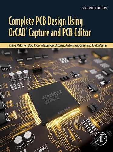
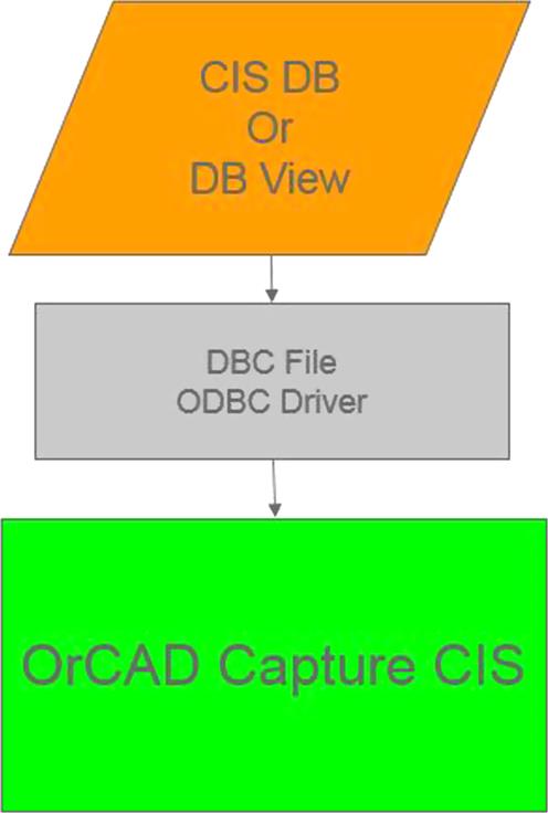
A simplified overview about the data structure of CIS is shown in Fig. 11.1. It shows how all the different data sources, files, and tools work together. There are two different main flows, one for the properties and the other for the symbols. All properties (metadata) are stored in a data source (database). In this structure, the open database connectivity (ODBC) driver and the database configuration (DBC) file format the data and forward it to the CIS user interfaces. The capture.ini file creates the connection between symbols and footprint values and the binary data, as it will be shown in the following sections.
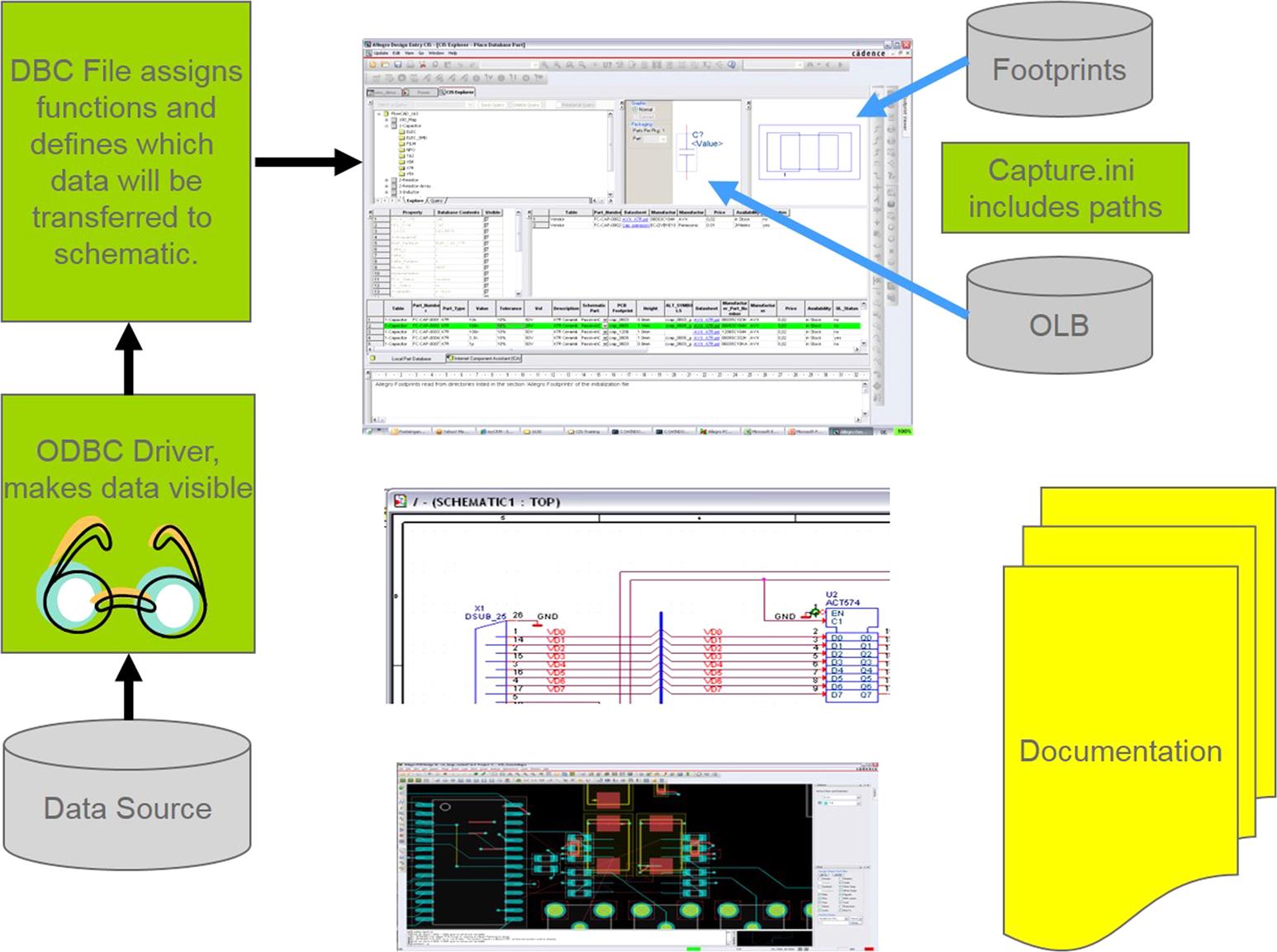
CIS may use a local or shared standalone database. This may be based upon an original extract of data from enterprise resource planning (ERP)/product lifecycle management (PLM) system; may have some periodic, typically overnight, update mechanism; or may be based upon database views created within the ERP/PLM database specifically for use by CIS to provide access to “live” data. The exact implementation details of the database will be determined by what data the company has and what use they wish to make of it (see Fig. 11.2 for example).
Properties in component information system
The previous section discussed about metadata, sources, properties, etc. Before starting to give information about how to do the different connections, and generate the ODBC driver and the DBC file, it is necessary to know the properties that must be included in a database. As mentioned earlier, it is company dependent, which properties are necessary to add to a database depending on the bill of materials (BOM), documentation, etc. However, in terms of CIS there are five mandatory properties that all part tables in your database must include (even when they are empty fields). These properties are as follows:
- • Part number: unique number CIS uses for communication with database. Never change this number, otherwise you will lose the connection to the database and need to link every single part manually to rebuild the connection.
- • Part type: creates the category tree view in CIS Explorer browser window.
- • Schematic part: name of the binary part description (OLB/schematic part). The OLB (OrCAD library) name is not mandatory, but it makes the search faster.
- • PCB footprint: used for preview in CIS Explorer and is mandatory for netlist generation.
- • Value: the shown value or type on the schematic page. Value is an intelligent property and it understands units and metric prefixes of resistance, capacitance, and inductance (such as Ohm, pF, and uH), because it is one of the major properties for PSpice.
If you want to use your schematic part for PSpice simulations, there are three other mandatory properties:
- • Implementation: usually the same as the part name. This should correspond to the MODEL declaration in the PSpice model file that represents this part.
- • Implementation type: for schematic parts to be simulated, its value should be PSpice model.
- • PSpice template: a long string of variables and pin name notations that link the pins on the schematic symbol with the PSpice model and is used for the PSpice netlist generation.
Note: The recommendation is to define these three properties in the schematic part, because with the procedure that we will see for the association of PSpice models in the section CIS and PSpice, such properties will be added automatically. It means that these properties shouldn’t be added into the database.
In addition to these properties, there are other optional properties depending in a part on the needs of your flow. The first step in creating a part database is to determine the properties to be included for each part. Typical properties in a part database are part description, tolerance, rating, speed, timing parameters, manufacturer, and cost. CIS supports an unlimited number of properties, so you can include as much information in your part database as you need. Define as much as you need but keep it simple as possible.
The names you use in the database can be different to the property names you assign to the placed parts. For example, you can name the Part Number property “My Company Part Number.” Also, you may call a property Tolerance in the database and Tol on the placed part. Database property types and placed-part property names are defined by separate DBC file that maps the fields in the database to the properties in the schematic.
Note: Do not use the same property name more than once. For example, if you have two manufacturer columns in your database, call them Manufacturer1 and Manufacturer2.
When you transfer a property, this property is included in the schematic as an attribute of the placed part. Normally, you transfer properties that are required by CIS (such as Part Number and Schematic Part), used in the design process (such as Value, Tolerance, and Rating), or needed for use by other software products (such as PCB Footprint). Properties that aren’t transferred can still be included in a BOM report.
Reserved properties
There are many property names that are reserved and cannot be used, such as
Transfer component information system properties to PCB Editor
It is not the main focus of this chapter; however, it is necessary to explain how to transfer the schematic part properties to PCB Editor in order to understand, why the properties issue is so important not only for PCB Editor. but also for bill of materials, documentation, etc.
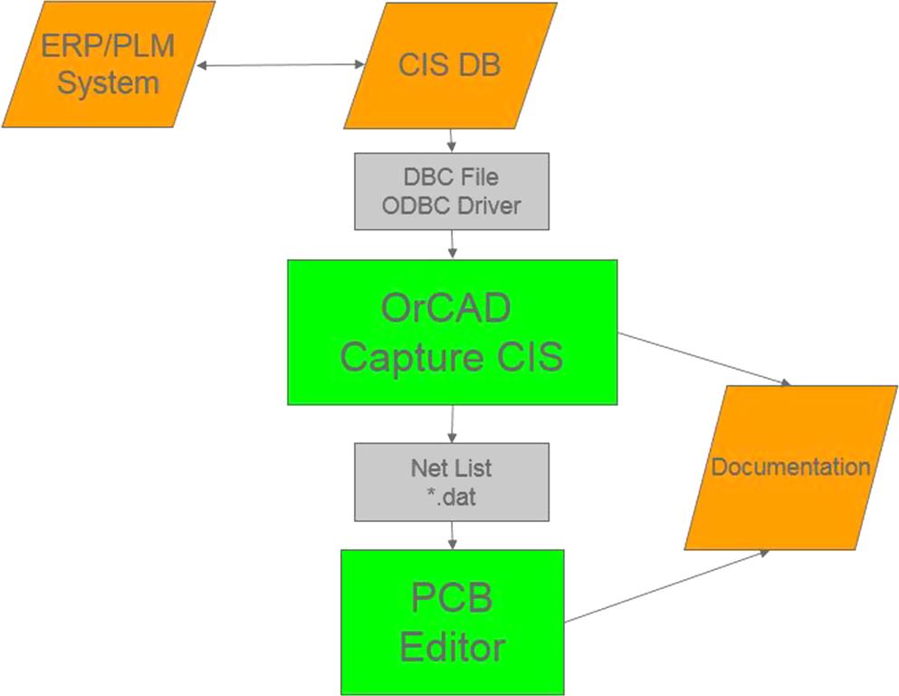
To generate the netlist for PCB Editor in OrCAD Capture CIS, select the design icon in the project manager window and click on Tools → Create Netlist. A window will pop up. Then click on the setup button like in Fig. 11.3.
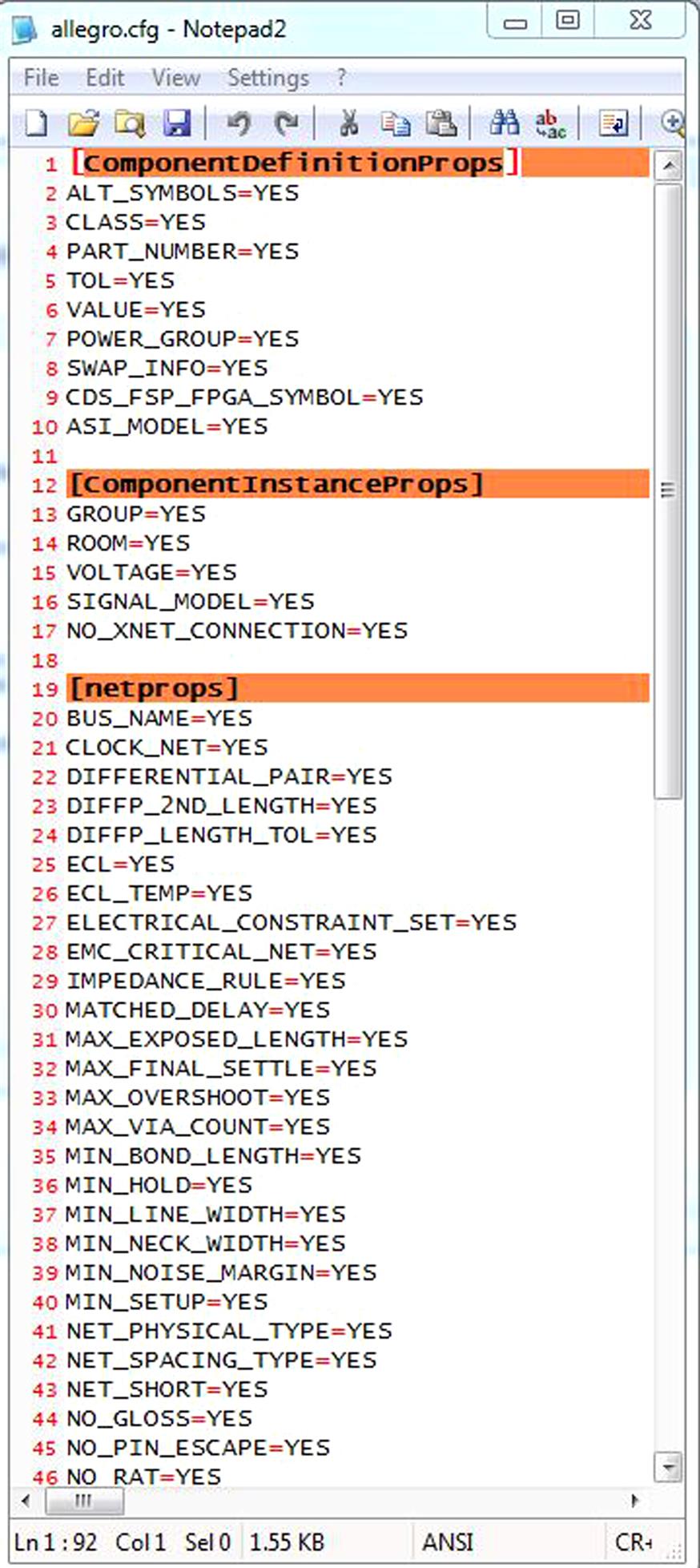
Use the Browse button (…) to choose the correct allegro.cfg. The standard file is stored in your OrCAD install directory oolscapture folder. Select Edit to open the file (Fig. 11.4). Add the missing properties you want to transfer to allegro in appropriate sections. The syntax is “Property Name=Yes”.

We recommend to store the changed allegro.cfg not in the install directory. Move it to a user-defined folder outside installation.
All properties in Capture can be transferred to PCB Editor. The allegro.cfg has five sections for the different types of properties as you can see in Fig. 11.5.
- • ComponentDefinitionProps—properties that are used to build the device type for the PCB Editor netlist. Don’t change this definition after you have started with Capture or DE CIS.
- • ComponentInstanceProps—all component properties that you want to transfer to PCB Editor in addition to the component definition properties.
- • Netprops—net properties for spacing, physical, and electrical rules.
- • Functionprops—a function is a part of a component. These properties are function based.
- • pinprops—pin properties.
You can customize the allegro.cfg to your specific flow and transfer user properties to PCB Editor.
Component information system administration
This section corresponds to an administrative task, which should be done just once in a company. It explains how to configure the ODBC driver with the database and how to generate the DBC file that is responsible for the management of the parts’ properties. It is also explained what the capture.ini is and what is its role in the CIS option.
Database systems
OrCAD allows us to use different kinds of databases. In the default installation, there is a configured SQLite database, which is free database software and easy to manage. However, it is possible to use text files (ASCII), Excel spreadsheets, Microsoft Access, and SQL database such as Microsoft SQL Server and Oracle. The first two ones may be used for testing or individuals. Access may be suitable for small workgroups, but database applications offer many advantages: comprehensive data management features, better performance for part searching, form-based entry for entering part information, safeguard against duplicate part numbers, and so on.
Before you create your database, you need to choose which database format you want to use. Then, when you create your database, you need to carefully set up its structure and organization including:
On the other side, CIS can work with database field formats for text and numbers. CIS converts different database field formats to text field format when properties are transferred to placed parts. From that perspective a good strategy is to use database views to change field format for the fields passed from existing data sources. This view can also be used to change Property Names to make them conform to CIS requirements. For example, in PLM or ERP systems the price information often may be with “currency” field format and with “gl-abc” property name, where GL means general ledgers, and ABC means activity-based costing. To get the OrCAD CIS flow working and more understandable for the users, create the “database view,” and change this field format to char or varchar and name it Price.
Note for SQLite: Use only ANSI SQL-92 compliant data types for your field formats. If you use noncompliant data types, CIS may misinterpret property values.
Connection of database and component information system
We are right now in the point that you already have defined a database with all required fields and records. Before you can start the CIS configuration, you need to define the ODBC data source for your database. This ODBC driver needs to be defined on every client system and the used data source configured must be consistent on all of the machines.
A data source consists of a database filename and an associated ODBC driver with which the database can be accessed from CIS. Because this driver needs to be defined on every client machine, it can be very time-consuming in larger teams. It can be configured by IT to manage ODBC driver as part of the user account.
If you are setting up a client-server database, or you want to link different databases, the ODBC driver also manages the connections between server and client or linked databases.
To set the ODBC driver for OrCAD 17.2, CIS needs a 64-bit driver. For that, click on Start → Settings → Control Panel → Administrative Tools → Data Sources (ODBC).
The settings file CAPTURE.INI
Capture.ini is a text file that every user needs to store in their OrCAD Capture settings. Per default, it is located in $HOMEcdssetupOrCAD_Capture17.2.0, where $HOME is defined by user variable HOME.
In this file we can find the most important information for OrCAD Capture. For CIS, we have to define
- • Part Management—location of DBC database configuration file
- • Footprint Viewer Type—Allegro per default
- • Allegro Footprints—directories where the footprints are located
- • Part Library Directories—directories where the part libraries are located
- • CIS Browse Directories—directories where documents referenced in CIS are located (e.g., PDFs)
In this file you can also include the global settings such as
The database configuration file
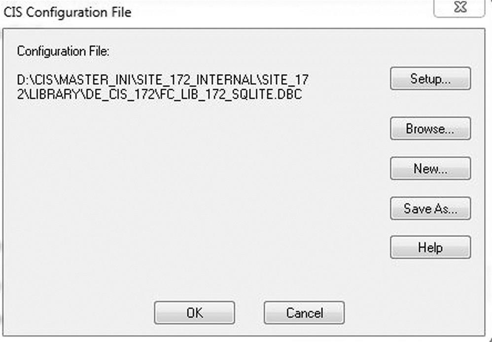
CIS requires a database configuration (.DBC) file to make use of your part database. That is why, the first step you have to do is to create a new DBC file, which goes to administrate the transferring data from your database (Fig. 11.6) . This configuration file
- • identifies the ODBC data source to use as part database and specifies the tables to use within that database;
- • identifies part properties that are transferred to your design, when you place or link a database part;
- • sets the visibility for each of the transferred properties;
- • contains the part type associations;
- • maps the property names.
Note: Keep the configuration (.DBC) file in a read-only directory that is accessible to all CIS users. You should make the directory read-only to prevent users from accidentally changing the configuration.
In OrCAD Capture CIS, you can access to this file by clicking on Options → CIS Configuration. Please consider that this option is available only when a design is opened. Immediately after clicking, a window, as shown in Fig. 11.7, pops up with many options:
Database configuration file—Part Database tab
After selecting Setup (it is considered that you have already defined a new dbc file) next window pops up (Fig. 11.8).

In the upper left corner, you find the name of the data source from the ODBC driver and a list of all available tables. You can choose which tables should be used by CIS by marking them.
The two grayed out columns are the data read from database. You can’t change this in DBC file setup. To change this data you should open the database.
On the right side of the picture, you can see Select Mapping Table. It can be set to add mechanical parts to your electrical parts. The mechanical parts are virtual parts (such as screws and nuts), which are only added to the BOM to create a complete export.
The configuration area defines all these properties:
- • Table property name—shows the property name as defined in the part database.
- • Table property type—the data type of the property.
- • Property type—one of six types indicating how Capture CIS interprets the property. Except for “Normal,” as you assign a certain type to one property, it is removed from the list of choices for other properties in the table. These assigned properties have special functions. The first four properties must be defined.
- • Part_number—used by the Part Manager to identify the part in the database. It is the unique key.
- • Part_type—contains the component categories, which we can see as a tree structure in CIS Explorer.
- • Schematic_part—name of OLB/Schematic part. It is transferred as a property.
- • PCB_footprint—footprint name for footprint preview and netlist generation.
- • PSpice_model—not mandatory. When you set this property type, CIS activates PSpice functionality for placed parts with a value for this database property.
- • Activepart_ID—no longer used.
- • Normal—use this for all other properties in the table.
- • Transfer to design—check to instruct Capture CIS to copy this property to the placed part when you place it on schematic sheet, or when you link the part with database.
- • OrCAD property name—the name of the property as it appears on the placed part. This characteristic is only available when you check “Transfer to design”. Select a property name from the drop-down list or type in the user property name. If you do not enter a value, the name of the property as it appears in the database is transferred to the placed part. Use this column to change property names.
- • Internet Component Assistant (ICA) property name—no longer used.
- • Visibility—sets the visibility of the property on the schematic design. You can change the visibility settings only for properties, which are transferred to the design.
- • Key—check to use the property as key during the initial part search when linking a database part. If you don’t have a value property, don’t set any key. You can specify any number of keys. Typically, you only set the key for the value property. When you link a part, Capture CIS searches for parts with that specific value in the database.
- • Browsable—check to indicate that this property in the database contains references to datasheets, drawings, or other documents. When you browse your local part database, click on hyperlink (blue, underlined) values to view the referenced documents online.
- • Update part property—check to instruct CIS to check the value of the property for placed parts against the database part’s same property value, when you update the part status of your designs.
 —property is always invisible.
 —property is always visible.
 —schematic part (from the OLB library) defines the visibility.
Database configuration file—Administrative Preferences tab
This tab in the DBC file configuration allows you to customize some CIS features for your work environment (Fig. 11.9).
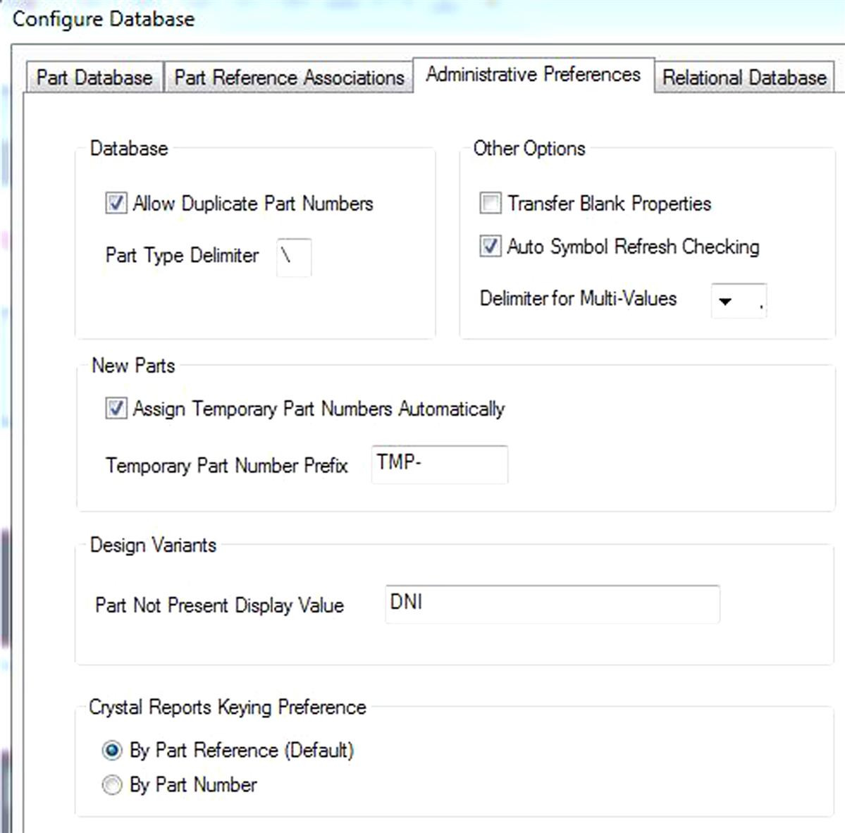
- • Allow duplicate part numbers—check to allow more than one part to use the same number in the database. This is most useful when you use parts with different associated mechanical parts. If you don’t use associated mechanical parts, disable this.
- • Part type delimiter—indicates the folder hierarchy delimiter used in the database. The default delimiter is the backslash. For example, if you use capacitorceramic in the database, Capture CIS displays ceramic as a folder in the capacitor folder.
- • Transfer blank properties—check to create a property on the placed part even if there isn’t a value for the property in the database.
- • Auto symbol refresh checking—check to enable CIS to automatically detect if symbols or footprints were updated in the configured libraries. If any changes are detected, the refresh symbols from lib command in the update menu of CIS Explorer and its corresponding icon on the toolbar are enabled. This indicates that you have to refresh the symbol or footprint information in CIS Explorer. If you do not select this check box, the refresh symbols from lib command in the update menu of CIS Explorer and its corresponding icon on the toolbar will always be enabled.
- • Delimiter for multivalues—select the character you want to use to separate multiple values in your part database.
- • Assign temporary part numbers automatically—check to have Capture CIS to create and track temporary part numbers. Temporary parts are tracked in the TMPPRTS table.
- • Temporary part number prefix—type the prefix you want to use for temporary parts, TMP is the default. Capture CIS appends the temporary part number to this prefix. You can set up a different prefix (such as the user’s initials) for each user’s temporary parts.
- • Part not present display value—the text description that you want CIS to use for variant parts set to not present (typical is DNI—Do Not Install). The property is displayed in the following locations:
- • Part Number and Value fields in the Part Manager.
- • Design variant columns in variant reports.
- • Variant parts on schematic page previews and printouts.
- • The part not present display value is not displayed in capture’s schematic core design. This property also cannot be repositioned or edited in the schematic page editor. A long value is more likely to overlap a display; therefore, try to use a fairly short text equivalent for the default Not Present value.
- • By part reference (default)—select this option to group and sort parts in BOM reports created using Crystal Reports grouped by part reference. Each part will have a unique item number. You can access part reference associations by clicking the Part Reference Associations tab in the Link Database Part command operation to improve the speed and accuracy of the search. When you choose Link Database Part, Capture CIS only searches for the associated database table and displays the parts of the appropriate type.
- • By part number—select this option to sort parts in BOM reports created using Crystal Reports by part number. Since part numbers are unique, the resulting report assigns one item number to all parts with the same part number.
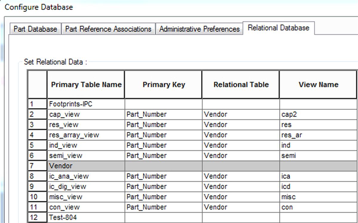
Database configuration file—Relational Database tab
In the Relational Database tab (Fig. 11.10), you define the relationship between the part (primary) and relational tables in the database. In the part table the part number must be unique. In the relational table, you can have several datasheets with the same part number to collect several vendors, part documents, and so on. So you can easily see the possible replacements for your part. You can connect one part table with one relational table not with several. The “Set Relational Data” grid contains the following fields:
- • Primary table name—use this list to define the part (primary) tables in your relational database. This is the only read-only field in the grid.
- • Primary key—use this list to define the primary key that you want to use to form the relationship with the relational table.
- • Relational table—use this list to specify a relational table that has a primary foreign key relationship with the selected primary table.
- • View name—use this text field to define a friendly name for the view that will display when a user selects the primary table to create a relational query. For example, you may have the separate table called “Vendor” where you have additional entries for different vendors of some capacitors. Say, you have eight replacements for a 100n capacitor. The original capacitor has the unique entry with internal Part Number = “FC-CAP-0099” in your database. Then in the “Vendor” table you can have eight entries of possible replacements with the same internal Part Number, and you can choose which one to use as a replacement (see Fig. 11.11).
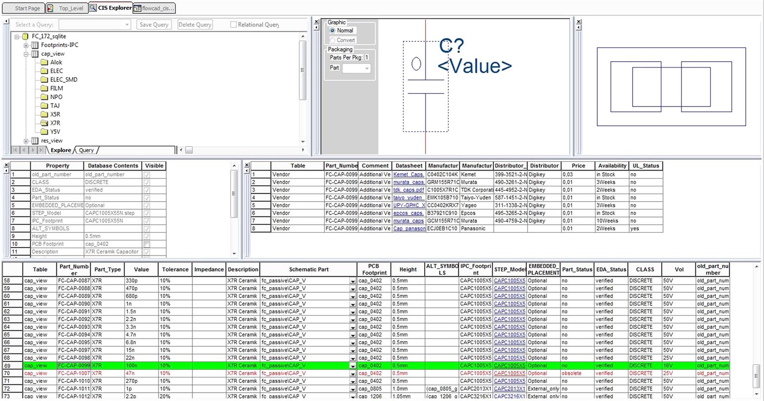
Once the database structure is defined, the ODBC driver is created, the DBC file is generated, and the capture.ini contains the proper directories, and it is possible to use CIS to design our schematics. To place the part from CIS database, run OrCAD Capture CIS, open the schematic page, and select Place → Database part from menu. The CIS Explorer window will appear, as shown in Fig. 11.11. Select the needed folder with parts in the database hierarchy, then choose the required part from the parts list in the bottom, and double click on it to place the selected component to the schematic sheet.
Component information system and PSpice
Simulation in PSpice is introduced in Chapter 9, Printed circuit board design examples. In order to perform the simulation, you need to assign proper PSpice models to your parts in Capture schematic design or Capture library. The OrCAD Component Information System helps to simplify this process and makes it more useful and convenient. This option is not very known by many users. It exists in addition to our database simulation properties as well. This section shows different situations that mostly cover the different scenarios connecting schematic parts and PSpice models. In this way, it is possible to keep parts not only for schematic design or PCB Editor, but for simulation as well. It makes the work much easier because everything is integrated in the same flow and the same component can be used for simulation, schematic design, and layout.
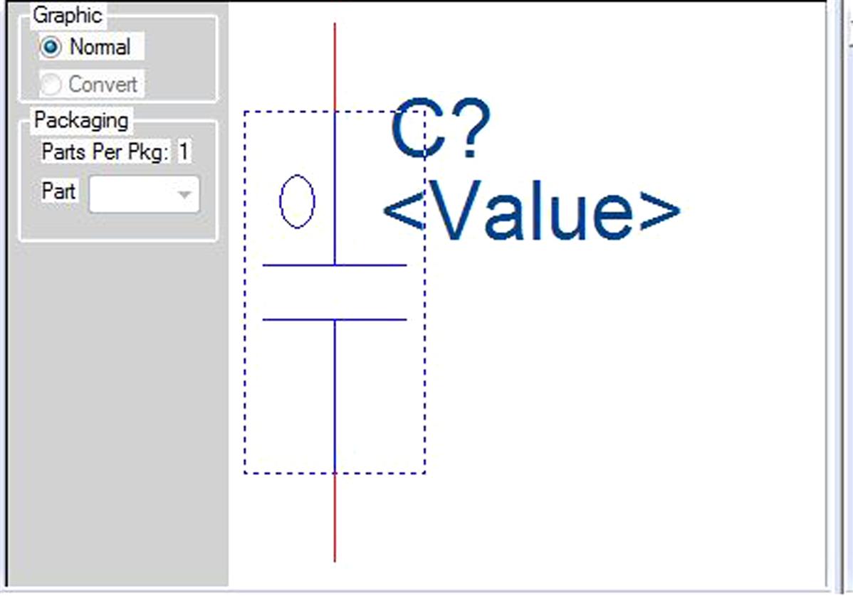
In the previous section, it was said that there are three mandatory PSpice attributes that must be considered and defined in a schematic part for simulation: Implementation, Implementation Type, and PSpiceTemplate. These attributes can be added as Properties on the schematic symbol (Fig. 11.12) or in the CIS database. If the property exists in both the symbol and the database, the database property overwrites the symbol property if placed through CIS. However, the recommendation is to define them in the schematic part, because using the option “Associate PSpice Model” such properties will be added automatically. Other properties such as Value or Tolerance should be defined in the database.

Note: Ideal resistors, capacitors, and inductors just need PSpiceTemplate, because they are not developed using model library (.lib). Real inductors and capacitors with parasitics use PSpice model (.lib), and they will have to be associated with the schematic part.
Ideal R, L, and C
Ideal resistors, inductors, and capacitors use only PSpiceTemplate property for simulation. This property should be defined in the schematic part. The procedure for that could be as follows:
- • Use directly the ideal R, L, and C schematic parts from the analog.olb library, which is available in the default OrCAD library.
- • If you want to use your own schematic part, then open the ideal R, L, or C from the analog.olb library in Capture, copy the value of PSpiceTemplate, and paste it in your schematic part. For that you will have to check that the pin names are the same ones as in the schematic part.
The value for such property depending on R, L, or C is the next one:
Resistor:
R^@REFDES %1 %2 ?TOLERANCE|R^@REFDES| @VALUE TC=@TC1,@TC2 ?TOLERANCE|
.model R^@REFDES RES R=1 DEV=@TOLERANCE% TC1=@TC1 TC2=@TC2|
As you can see, the resistor PSpiceTemplate value is referencing to different other property values. These values could be defined in the database or in the schematic part:
Please consider that the pin names of your schematic part must be the same as the pin names in the PSpiceTemplate. In this case the pin names are 1 and 2 (as you can see in the PSpiceTemplate definition for the resistor). So if you have a schematic part with the pin names A and B, you should change the PSpiceTemplate accordingly.
Inductor:
L^@REFDES %1 %2 ?TOLERANCE|L^@REFDES| @VALUE ?IC/IC=@IC/ ?TOLERANCE|
.model l^@REFDES IND L=1 DEV=@TOLERANCE% TC1=@TC1 TC2=@TC2 IL1=@IL1 IL2=@IL2|
As you can see, the inductor PSpiceTemplate value is referencing to different other property values:
Capacitor:
C^@REFDES %1 %2 ?TOLERANCE|C^@REFDES| @VALUE ?IC/IC=@IC/ TC=@TC1,@TC2 ?TOLERANCE|
.model C^@REFDES CAP C=1 DEV=@TOLERANCE% TC1=@TC1 TC2=@TC2 VC1=@VC1 VC2=@VC2|
As you can see, the capacitor PSpiceTemplate value is referencing to different other property values:
The way you could define these components in the database is quite simple. One proposal is to define the PSpiceTemplate property in the schematic part and the other properties in the database.
C and L with parasitics
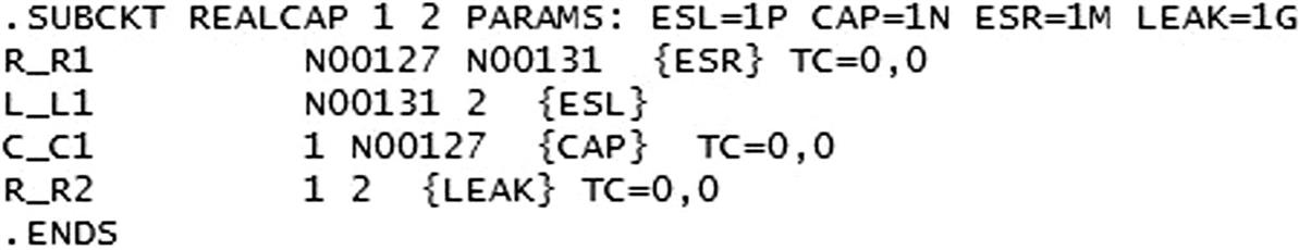
In some precise circuits, it may be important to define the passive components with their real parasitic parameters, to make the simulation more accurate. In such case, C and L are defined using a PSpice model. It means that you could have a subcircuit as a PSpice library (name.lib) text file containing the preliminary created or downloaded PSpice model, as shown in Fig. 11.13 (where ESL, CAP, ESR, and LEAK are the parasitic parameters; C_C1 is the base capacitance; and R_R1, L_L1, and R_R2 are the parts of the subcircuit which serve in this model as the parasitic components of real capacitor). The creation of PSpice models as subcircuits directly in OrCAD Capture is described in Chapter 7, Making and editing Capture parts.
Consider that you have your schematic part for C or L without the PSpice properties defined. It means that such C and L are not yet defined for simulation. The procedure to associate a PSpice Model to such schematic part is
- 1. Open the parts library (.olb) where the schematic parts are included. For example, our parts are CAP_H and IND_H as shown in Fig. 11.14.
- 2. Double click on CAP_H. You will see that this schematic part is not prepared for simulation, because Implementation Type, Implementation, and PSpiceTemplate properties are blank (Fig. 11.15).
- 3. Close this window, highlight the capacitor, and right click on Associate PSpice Model.
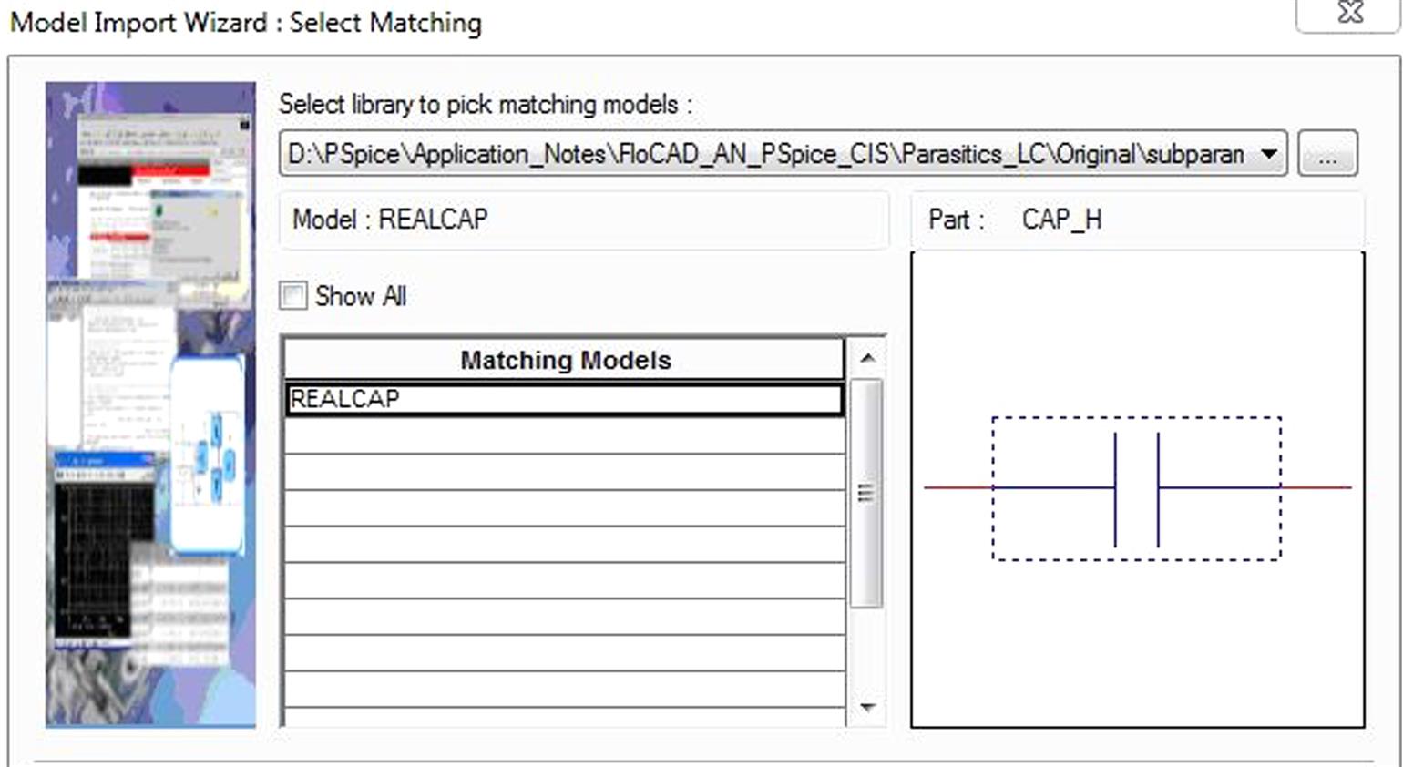
- 4. Select the library (.lib) where the PSpice model is located and choose the appropriate model from the list of available models (Fig. 11.16).
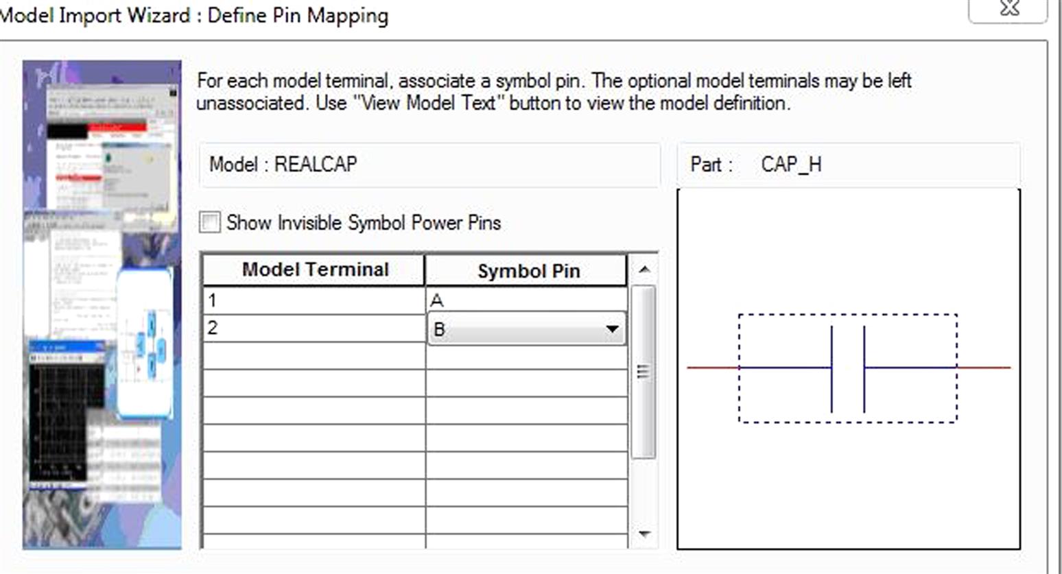
- 5. Click on next and associate each model terminal with schematic part pin (Fig. 11.17).
- 6. Click OK. Your schematic part is now available for simulation.
- 7. Double click on the capacitor and observe its properties. PSpiceTemplate, Implementation Type, Implementation, and the parasitics parameters ESL, ESR, CAP, and LEAK are automatically defined (Fig. 11.18).
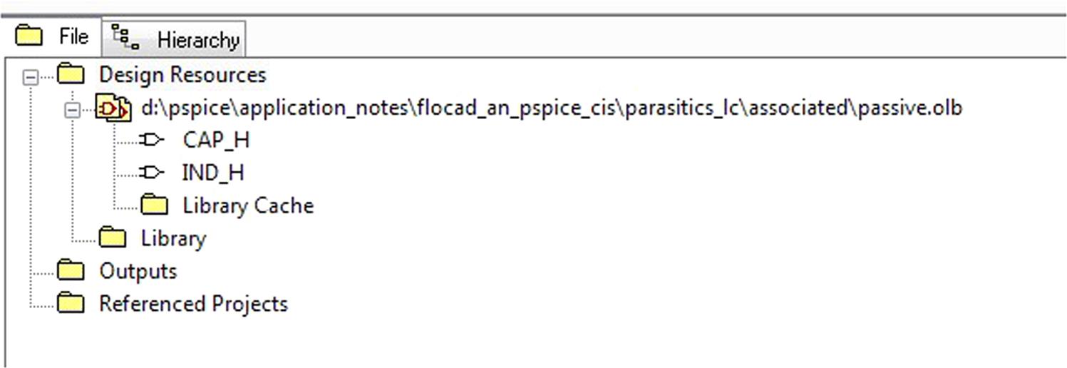

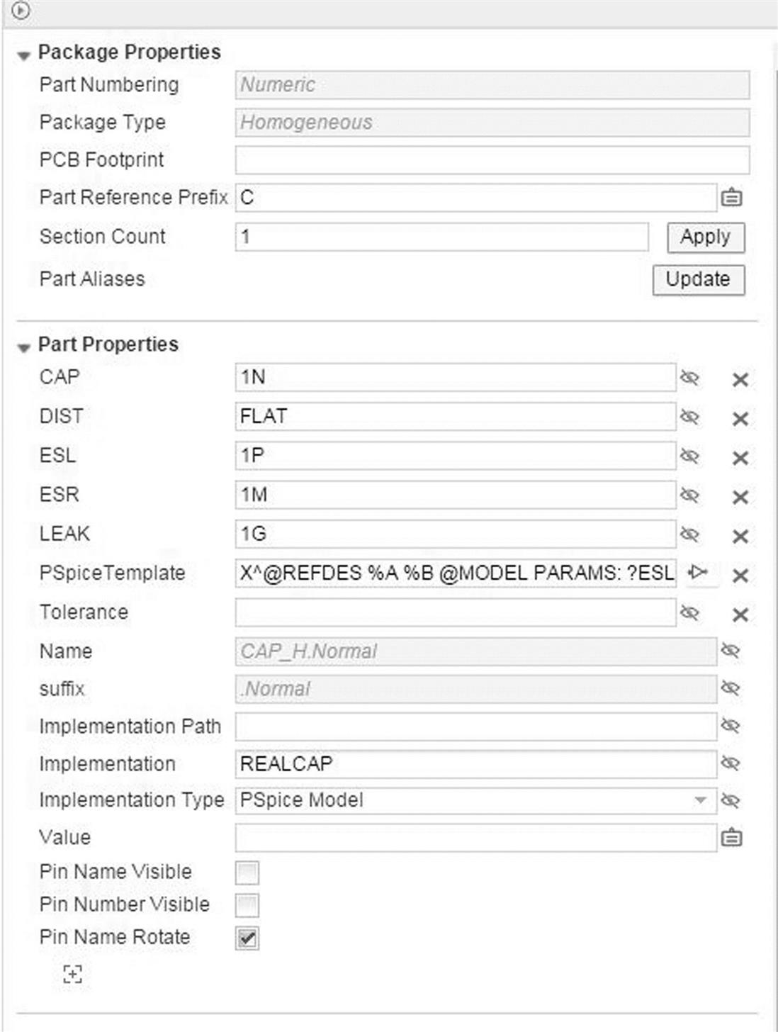
Now you can manually include this new schematic part into the database. In the database, you should define new columns, where the parasitics parameters ESL, ESR, CAP, and LEAK with particular values are considered. When you place such component, values of database are transferred to the design. Thus, you may have many different capacitors in the database, with different values of capacitance and parasitic parameters, but all of them can be based on the same library part (symbol), named CAP_H in this case and stored in the PASSIVE.OLB library (Fig. 11.14).
Association of schematic part with PSpice model
In the previous paragraph, we described the steps to associate a PSpice model to a schematic part. When you have a schematic part without a PSpice model (e.g., a transistor, an opamp, IC), all you have to do is to associate PSpice model to this part, so that the pin mapping and the PSpice properties are automatically defined.
Homogeneous parts and PSpice
Suppose you have an IC package with four identical opamps inside. All you have to do to use homogeneous parts with CIS and PSpice is to associate the schematic part with the PSpice model. Then each opamp of the package will be automatically assigned to the PSpice model, and it will be possible to run a simulation.
Heterogeneous parts and PSpice
The heterogeneous parts are not supported by PSpice.
Schematic parts with more pins than the PSpice model
Consider you have a schematic part, which has more physical pins than needed for simulation. In order to allow simulation, you have to define such extra pins as Unmodeled.
In order to understand this better, consider the operational amplifier ua741 as an example. This package has eight pins, but for simulation just five pins are sufficient (in+, in−, V+, V−, and OUT). In the schematic part, click on each pin that is not used for simulation (Fig. 11.19).
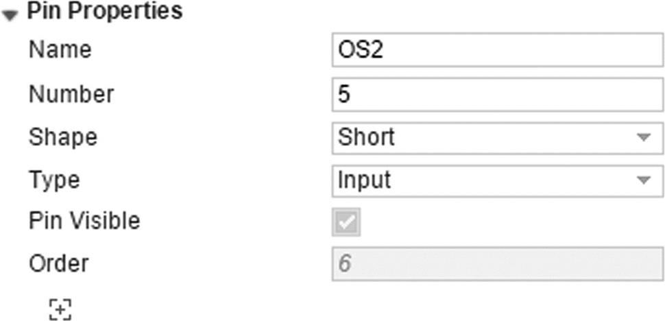
Then click on the + to add a new Pin Property, select FLOAT from the drop-down list of properties, enter Unmodeled and left-click the “tick” to set the property (Fig. 11.20).

Doing this, it is possible to simulate schematic parts that have more pins than the pins that are used for simulation.
How to simulate a project designed for both printed circuit board design and simulation?
In this type of projects, there are some blocks of schematic that are not necessary for simulation. For example, you could have a DDR2, DDR3, FPGA, power supply, etc. but only the power supply must be simulated. The questions would be “Do I have to create a new project to simulate just the power supply?”. The answer is no. If you are using the schematic–simulation–layout flow with CIS, the components that you placed for designing the power supply block will be already suited for simulation. All you have to do is to create a Test Bench, which will contain a part of your schematic design for simulation. To create the Test Bench, run OrCAD Capture CIS, and follow the next steps:
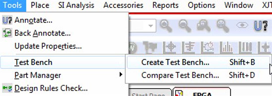
- 1. Open your project, select design icon or schematic folder, and click on Tools → Test Bench → Create Test Bench (Fig. 11.21).
- 2. Automatically a window pops up. Write the name for the Test Bench.
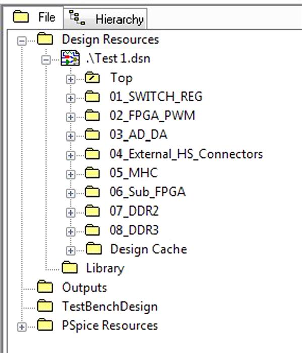
- 3. The Test Bench appears in the project manager tree (Fig. 11.22).
- 4. Double click on it. Automatically a new design with the name name.dsn pops up. This design is identical to the original one.
- 5. Make root the schematic you want to simulate. In this case, make the root 01_SWITCH_REG using right click and selecting Make Root (Fig. 11.23).
- 6. Open the circuit on this schematic and you will see that all components are gray. It means that they actually are “invisible” for the simulation. So if you want to consider them in the simulation you have to select each one you need and right click on TestBench → Add Part(s) to Self (Fig. 11.24).
- 7. Now these components are colored again. It means that they are no longer invisible and they will be used for simulation.
- 8. Now you can place sources or whatever you need for simulation.
- 9. Create a simulation profile, simulate, and analyze the results.
- 10. Follow the same steps if you want to simulate another block (schematic) of your design.


Working with component information system
This section explains the working of CIS for the daily work of Capture users. It is actually the common use of this option.
Find and place parts
To find and place the CIS database part to the schematic sheet, select Place → Database Part from the Capture CIS menu while you are in the schematic page view, then the CIS Explorer window will open (Fig. 11.11). The CIS Explorer window allows you to search for and retrieve a variety of part information.
The CIS Explorer window consists of several panes:
- • Explorer window (Fig. 11.25) allows you to search for parts using local data from your preferred part database. The window contains two tabbed sections, Explore and Query.
- • In the Explore tab, you can search for parts using a hierarchical tree organized by part type.
- • The Query tab allows you to further filter your selection based on parametric or field data and to save the created queries for later use. You can combine several properties with different compare actions.
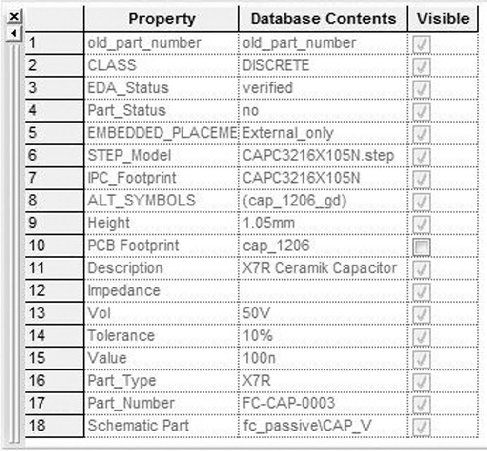
- • The visibility window (Fig. 11.26) displays the default settings for which part properties are visible on your schematic page. You can use the visibility window to override these default settings for single parts. You can also use the visibility window to display a compact summary of the part properties and their contents for the part you have selected in the database parts window. You can see more of the properties and contents in this view because the visibility window displays them in rows rather than columns.
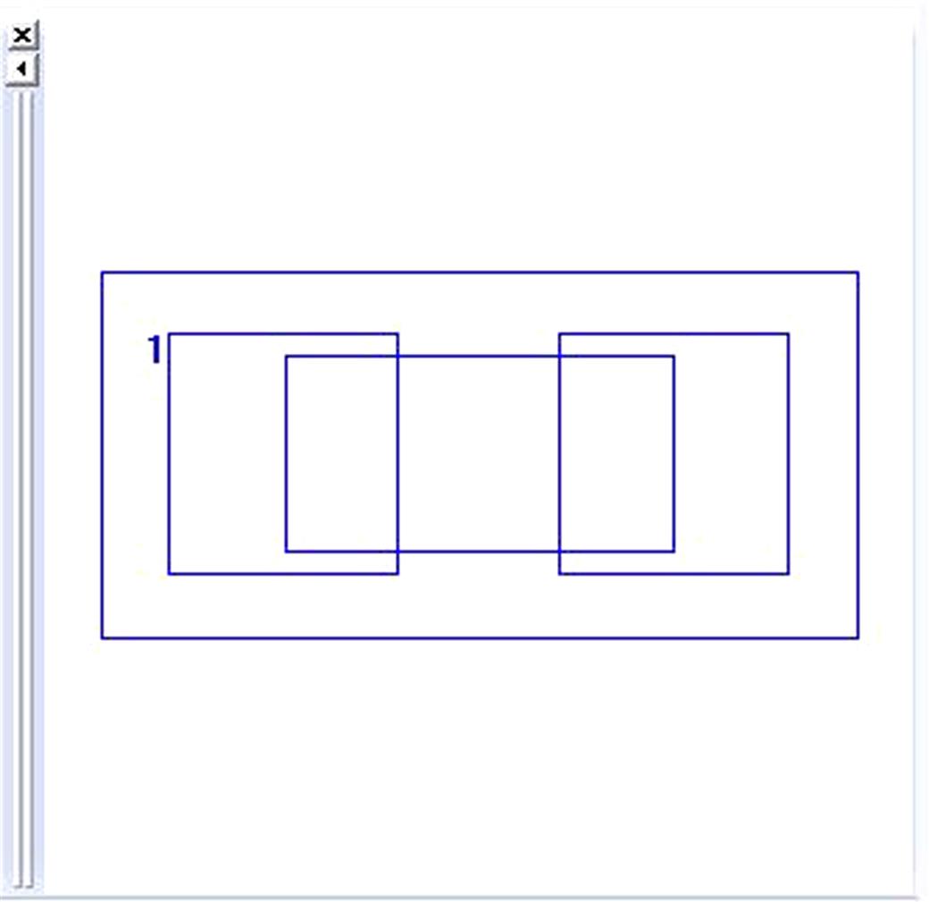
- • The footprint window (Fig. 11.27) displays the PCB Editor generated PCB footprint associated with the currently selected database part.
- • The part window (Fig. 11.28) displays the schematic symbol and packaging data of the capture library part associated with the currently selected database part. For a multiple-part package, you can select the specific part in the package.
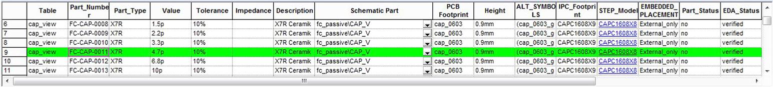
- • The database part window (Fig. 11.29) displays the results of your part browsing and database queries. Double click on the selected part row will open the schematic window and will allow you to place the selected symbol on the schematic capture canvas. The placed part is still “linked” to the database, so it will not only inherit the properties from the database record, but also will remember from which record it was placed, and will allow to see that record later if you need.

When you select a part in the database parts window, the relational table view window (Fig. 11.30) displays all relational information that are connected to the current electrical part.

Part Manager
The Part Manager window summarizes the status of all the parts in your design and provides a graphical interface for creating BOM variants. You can open the Part Manager window by selecting Tools → Part Manager → Open menu while you are in the Project Manager window (Fig. 11.31).

The left side pane displays a tree view similar to Windows Explorer. The tree view is a hierarchy of groups, subgroups, and BOM variants found in a design.
The right side pane of the Part Manager displays a list view with information of each part in your design. You can configure the Part Manager window to show other part properties in addition to the standard part information.
In this sense the green color in each part means that the part matches the definition in CIS database. Yellow means that the part is defined but not checked. Finally, red means that the part has no Part Number property value, or has a Part Number property value that has not been found in the current database.
Customize Part Manager
To configure the part property display, just click on View → Configure Part Property Display. After that a window pops up (Fig. 11.32). All Properties in Selected part properties column are shown in Part Manager. Use Add/Remove button or double click to move properties to the other column.
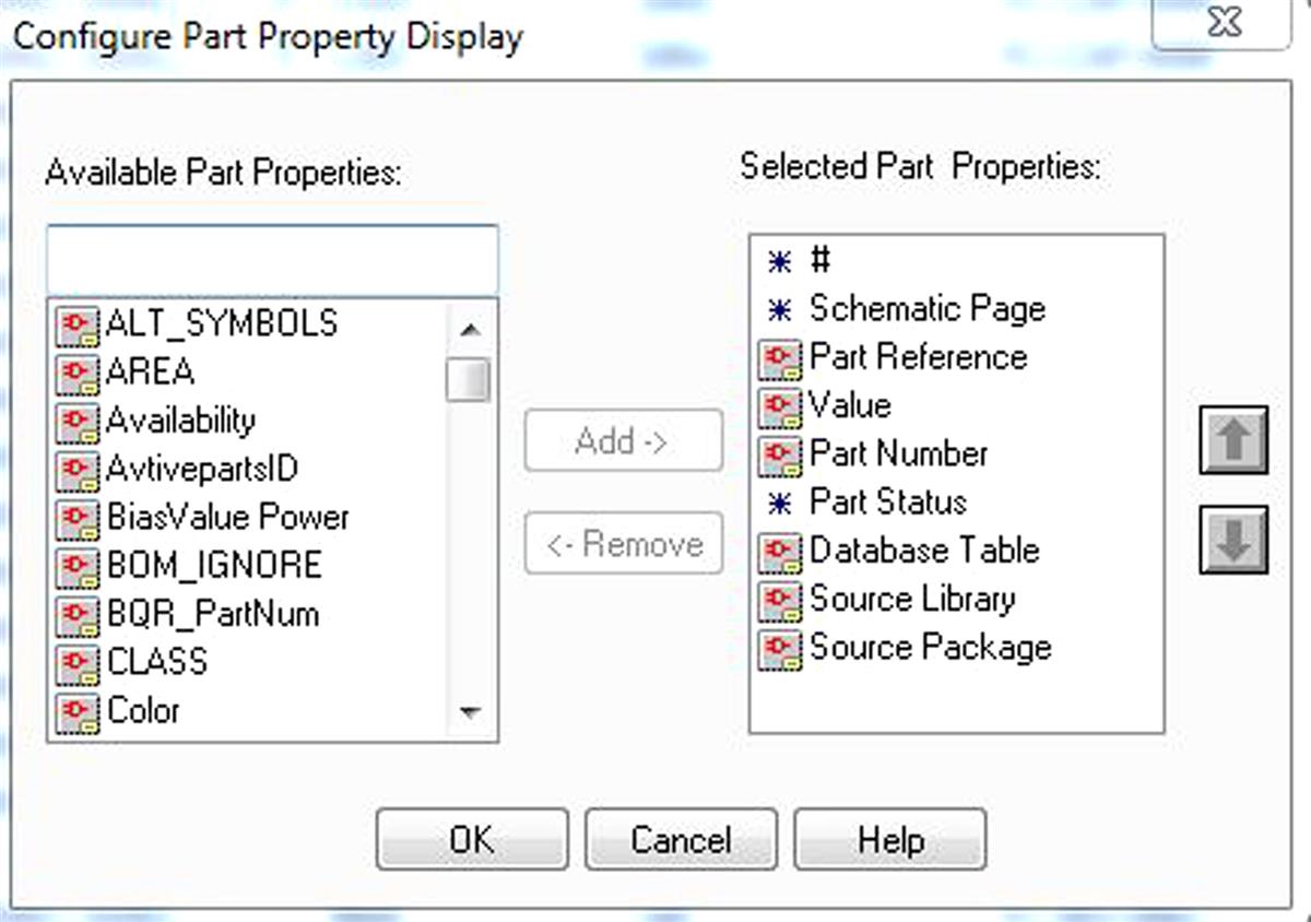
Never remove the three properties marked with an asterisk (#, Schematic Page, and Part Status).
Part Manager features
With Part Manager opened, you have many options to do with each component. By right clicking on a single part or group of similar parts you can start these actions:
- • Link database part—replace the part with a different library part
- • View database part—opens CIS Explorer and shows part
- • Update selected part status—synchronize a single part with central database
- • Update all part status—synchronize all listed parts with central database
- • Goto Part on Schematics—opens Capture page and shows part
Note: Under Options → Update Part status, you have the option to enable or disable Verify Parts against .OLB libraries. If it is enabled, the command Update Part Status also checks the cache against central library part.
Bill of materials
In Capture, it is possible to generate a BOM using the capture BOM command (Tools → Bill of Materials). CIS provides its own BOM command that lets you generate BOM reports based on the data in the parts database, as well as properties added to part instances after they have been placed in schematics. CIS Bill of Materials offers additional options for generating part reports.
You can generate a CIS Bill of Materials in two formats:
When generating a standard CIS BOM (Reports → CIS Bill of Materials → Standard), you use the standard Bill of Materials dialog shown in Fig. 11.33 to create a BOM template specifying which properties from the parts database to include in the BOM and how to sequence them. You can create multiple BOM templates specifying different combinations or arrangements of part data to report. When you need to generate a BOM, you choose the appropriate template for your purpose.
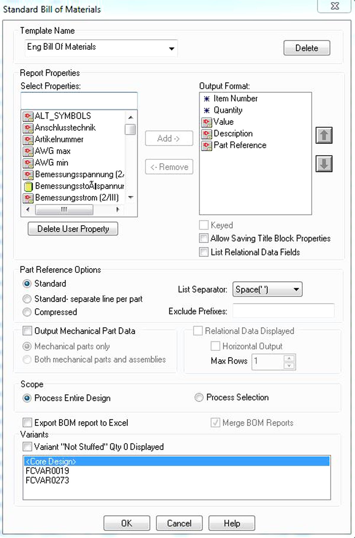
The Select Properties box lists all available properties you can include in the BOM report. The Output Format box lists the properties you want to include and the sequence in which their columns will appear in the BOM.
If you select a property in the Output Format list and check the Keyed check box under the list, parts having that property are grouped together on the BOM.
You can choose the list separator you need.
The Exclude Prefixes box provides a way to filter out data for certain types of parts from the BOM. For example, suppose you use the prefix “TP” in part references for all test points. To exclude those parts from the BOM, you would enter TP in the Exclude Prefixes box.
You can enable Relational Data Displayed and define the format to include them to BOM.
You can define the Scope. In hierarchical designs, you can define BOM on entire design or hierarchical block level.
When you have the variant description with “not assembled” component you can choose the BOM format for these parts. Enable Variant “Not Stuffed” Qty 0 Displayed to get all not assembled parts with the quantity 0 in the BOM. Without this option, all not assembled parts are ignored.
Variants
With CIS option you get the powerful possibility of creating the variants of your schematics, for example, with different part values or “not assembled” parts depending on application. The terminology of the variants is the next one:
- • Groups—multiple components are generally used to support a particular function or module (e.g., a power or memory module). These components are defined as a group and have varying version numbers.
- • Subgroups—each subgroup represents a version or assembly of the parent group. For example, if your power module has different assemblies for Europe and Asia, then the Power group would have two subgroups. The set of components in each subgroup is the same as the parent group.
- • Core design—the core design is the base schematic and PCB from which design variants can be created.
- • Common—all components that are not part of a group but are still part of the core design. These modules or functions remain unchanged in all assemblies.
- • BOM variants—the versions of the design that are manufactured from a BOM that is specific to each assembly.
For example, in the PCB project shown in Fig. 11.34, the hatched areas are functions with different variant information:
- • The large red one, on the left side, is the power supply. It has three assembly variants.
- • The green one in the top is the channel block with two assembly variants.
- • We have marked eight different blocks and we need to define eight groups. The subgroups contain the assembly variants, three for power supply [220 V, 110 V, and Not included in Design (DNI)], and two for the channels (one channel or two channels).

All components in nonmarked areas have no variant and stay in common group.
The steps to create the variants are as follows:
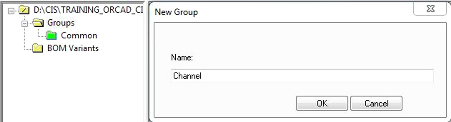
- 1. Open Part Manager and create several new groups for the components that have variant assemblies, by right clicking and selecting New Group. In the case of the example of Fig. 11.34, there are eight different groups. As example, we show the definition for two of them: Channel and Power (Fig. 11.35).
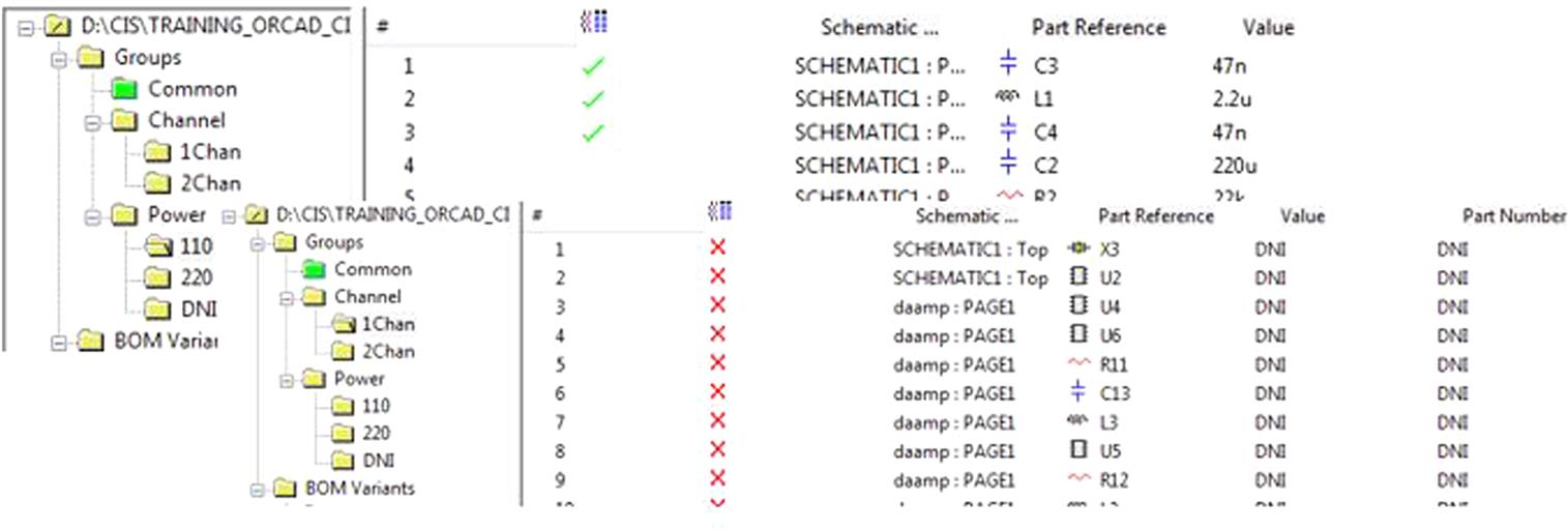
- 2. Create subgroups for every variant of the group. For the Channel block, there are two variants: 1Chan and 2Chan. For the Power, there are three variants: 110, 220, and DNI, as shown in Fig. 11.36.
Finally, close the Part Manager. - 3. Go to the schematic pages and sort the components into groups by selecting the needed components and right clicking on the menu Add Part(s) to Group, as shown in Fig. 11.37.
- 4. Open Part Manager and define the alternate and not assembled components in the groups (see Fig. 11.38).
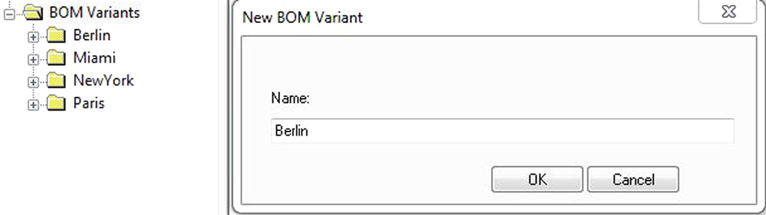
- 5. Create BOM variants. Right click on BOM variants folder and create a new BOM variant (Fig. 11.39). For example, we define four variants Berlin, Miami, NewYork, and Paris.
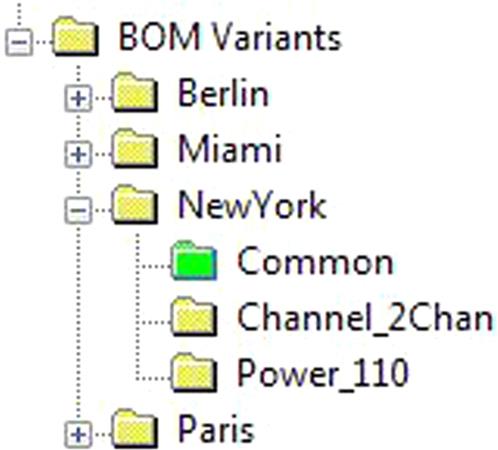
- 6. Move the subgroups to the BOM variants. For that drag the folder of the subgroup to the variant you want. For example, move the subgroups 110, 2Chan, and Common to NewYork (see Fig. 11.40) .
- 7. Move the Common group with the rest of the components to every BOM variant.


To see the variants in the schematic, click on View → Variant View Mode and select the desired variant. In default color settings, all alternate values are shown in green and all not present parts are shown in gray. You can change these colors in Options → Preferences.
Note: You can also generate variant BOM reports under Reports → Variant Report.