
PETRUCHIO: And, for an entrance to my entertainment,I do present you with a man of mine,[Presenting Hortensio.]Cunning in music and the mathematics,To instruct her fully in those sciences,Whereof I know she is not ignorant:Accept of him, or else you do me wrong:His name is Licio, born in Mantua. | ||
| --The Taming of the Shrew, II, i, 54–60. | ||
Previous chapters have addressed the topic of assurance in general and have described how assurance can be acquired throughout the life cycle of a product or system. To this point, the methods and techniques that have been discussed have been informal in nature and dependent on documentation and written requirements statements for design assurance and on testing for implementation assurance. Chapter 19, “Building Systems with Assurance,” introduced the concepts of formal specification languages for specifying requirements and systems as well as mathematically based automated formal methods for proving properties of specifications and programs. This chapter discusses these topics more fully, examining past and present formal specification and proof technologies.
As in the techniques discussed in previous chapters, formal verification techniques rely on descriptions of the properties or requirements of interest, descriptions of systems to be analyzed, and verification techniques for showing that the system descriptions are sufficient to meet the requirements. The difference between the formal methods and those described in Chapter 17 is the degree of formality of the approach.
Part 3, “Policy,” presented a variety of formal and informal security policy models. The formal models are presented in the language of mathematics. This chapter introduces other formal languages, called specification languages, that are useful for representing policies, models, and system descriptions. These languages have well-defined syntax and semantics and are based on a mathematical logic system. This chapter also addresses formal verification techniques that process the formal specifications, determining how well each specification meets the requirements stated in the policy/model or requirements specification. All verification techniques rely on the underlying structure of some mathematical logic system and the proof theory of that logic. Chapter 34, “Symbolic Logic,” provides a very brief overview of several logical systems that are used in formal proof technologies and presents fundamental definitions and theories. The reader who is inexperienced in logical systems should review that chapter before proceeding.
Although all formal verification techniques implement similar concepts and approaches, current trends have divided these techniques into inductive verification techniques and model checking techniques. The differences between these two types of techniques are based on the intended use, degree of automation, general logical approach, and underlying logic system. Huth and Ryan [503] provide an excellent set of criteria for classifying verification technologies.
Proof-based versus model-based techniques. Proof-based techniques define a set of formulas called premises that embody the system description and another formula called the conclusion that represents what is to be proved (the properties). These techniques rely on finding a set of intermediate formulas that allow the verifier to reach the desired conclusion beginning from the premises. Model-based techniques rely on establishing that the premises and the conclusion exhibit the same truth table values.
Degree of automation. Approaches vary from fully automated to fully manual, with every possibility in between.
Full verification versus property verification. The system specification may describe an entire system or parts of it, and the property specification may be as small as a single property or may contain many properties.
Intended domain of application. This may be hardware or software, sequential or concurrent, reactive[1] or terminating, or other types of systems.
Predevelopment versus postdevelopment. A verification technique may be intended to be used as a design aid or for verification of the system after the design is complete.
Inductive verification techniques are typically more general in nature. Some of the techniques we discuss below were designed to be general-purpose software development methodologies, addressing all stages of the life cycle. Other inductive verification systems simply provide mechanisms for proof of theorems. All are based on generation of formulas that show that a specification of a system meets the requirements of a set of properties. These techniques often have separate steps to create formulas that claim that the specification meets the properties. These formulas are submitted to a theorem prover that uses a higher-order logic such as predicate calculus. The theorem prover attempts to show that the premises and conclusion are provably equivalent by finding a series of proof steps starting with the premises of the formula and eventually reaching the conclusion of the formula. The user of an inductive verification technique generally guides a theorem prover in finding a proof by supplying lemmata and previous results that can be used to prove more complex theorems. Some inductive verification techniques are used in the development cycle to find flaws during the design process. Others are used to verify the properties of computer programs.
Model checking techniques also establish how well a specification of a system meets a set of properties. The systems modeled are state transition systems, and a formula may be true in some states and false in others. Formulas may change truth values as the system evolves from one state to another. The properties to be verified by a model checker are formulas in a temporal logic. In temporal logic, truth or falsehood of a formula is dynamic and is not statically true or false as in propositional and predicate logic. Section 34.3, “Temporal Logic Systems,” presents an example of a temporal logic system.
Typically, a model checker addresses a single model that is built into a tool or given to the tool as a specification of external properties. The tool is usually automatic, with little or no interaction with the users' point of view. Formula generation and proof are a single step from the user view. The model checker attempts to show that the model of the system and the desired properties are semantically equivalent, which can be described by saying that the model and properties exhibit the same truth table. The user initiates the model checker and waits for the results. The model checking approach is often used after development is complete but before a product is released to the general market. Model checking was designed for concurrent systems and systems that react to the environment and that are not expected to terminate.
The final section of this chapter addresses the analysis of cryptographic protocols, which lends itself nicely to the use of formal methods. The protocols themselves are relatively small and contained but may present complex and exploitable flaws. Protocol verification has been a hugely popular topic in the computer security research community over the past decade. Protocol verification has been accomplished using inductive proof methodologies as well as model checkers, and there are several special-purpose protocol verification methodologies in wide use. Many are based on the knowledge and belief logics of Burrows, Abadi, and Needham [163], and others describe the interactions of a set of state machines to attempt to prove that a protocol is secure.
Recall that a specification is a description of characteristics of a computer system or program. A security specification specifies desired security properties. (See Definition 19–7.) To this we add the definition of a formal specification.
Definition 20–1. A formal specification is a specification written in a formal language with a restricted syntax and well-defined semantics based on well-established mathematical concepts.
Formal specifications use a language with precise semantics. This avoids ambiguity and may allow for proofs of properties about the specification. These languages support precise descriptions of the behavior of system functions and generally eliminate implementation details.
Generally, the specification languages are supported by automated tools for verifying the correct use of the language syntax and semantics. Inductive verification, protocol verifiers, and model checkers use formal specification languages as input to the tools of the technique, making a formal specification a part of any formal verification technology. Formal specification is also important as a stand-alone technique. The specification may or may not be needed for some proof process. The process of writing formal specifications helps us to understand the design better and to see potential flaws, even without claims and proofs.
SPECIAL is a first-order logic-based language developed at SRI, International, as a stand-alone specification language. SPECIAL provides an excellent example of a nonprocedural and strongly typed specification language that is well suited for writing functional specifications, as described in Chapter 17. The strengths of SPECIAL are the richness of its expressive capability and its ability to describe inputs, constraints, errors, and outputs without implementation details. SPECIAL has a rich set of built-in operators, including set operations such as UNION and DIFF; logical operators such as AND, OR, and => (implies); universal and existential quantifiers (FORALL, EXISTS); IF/THEN/ELSE constructs; arithmetic operators; and many others. SPECIAL also has a mechanism for distinguishing an old value of a variable from a new value.
A specification in SPECIAL represents a module, and the specifier defines the scope of the module. Several modules can be used to describe a system. Two good reasons to make smaller modules are convenience and ease of manipulation, but another reason is to take advantage of the ability to hide information between modules.
A SPECIAL module specification has several sections for describing types, parameters, assertions, and functions. SPECIAL types are identified syntactically using keywords in capital letters. Two examples are the DESIGNATOR type, which allows the use of a type whose specifics are to be defined at a lower level of abstraction, and the BOOLEAN type, which includes the values TRUE and FALSE. SPECIAL also supports discrete sets, sets defined in terms of other types, and structured types. Parameters define constants and entities whose ability to change is outside the scope of the specification. Definitions are a shortcut for complex expressions that need to be used repeatedly. Global assertions can be made about the other elements of the module and can be used in proving theorems about the specification.
The heart of the SPECIAL specification is the functions, which define state variables and state transitions. Any function can be defined as private to the scope of the module in which that function is defined or as visible and addressable outside the specific module description. The visible functions define the external interface to the module. A visible function may have an exceptions clause that lists the conditions to be tested and passed for the effects of the function to take place. VFUNs describe variable data. Primitive VFUNs describe the system state variables, whereas derived VFUNs provide values determined by expressions involving primitive VFUNs, which have an initial value. VFUNs are viewed as functions that return a value to the caller and thus contribute to the definition of the system state. OFUNs and OVFUNs describe state transitions. They have exception sections as well as an effects section that describs changes in VFUN values. Like OFUNs, OVFUNs describe state transitions, but, like VFUNs, they also return a value and thus are state transition functions and contribute to the state of the system. Any function specification can contain “local” assertions that are specific to the function.
Some early work in formal methods attempted to mechanize and formalize the entire development process. This approach met with only limited success but provided invaluable lessons that led to further research that produced more useful results. Other early work led to modern-day model checkers, and still other early work analyzed communications protocols. This work demonstrated the importance of the individual components by themselves and not just as parts of an overall method. More recent research has focused on more specific entities (for example, one part of the overall picture, such as proofs, and one type of system, such as cryptographic protocols).
In the 1970s and 1980s, several formal verification systems were developed. The most well-known of these systems are described in Cheheyl et al. [191], from which much of the material in this section is drawn. We will discuss two verification systems to illustrate the basic concepts of verification. The Enhanced Hierarchical Development Methodology focuses on proofs of design, whereas the Gypsy Verification Environment focuses on proofs of implementation.
The Enhanced Hierarchical Development Methodology (EHDM) was strongly based on its predecessor, the Hierarchical Development Methodology (HDM) [770]. HDM was a general-purpose design and implementation methodology. Its goal was to mechanize and formalize the entire development process, providing reliable, verifiable, and maintainable software. The HDM package addressed design specification and verification as well as implementation specification and verification, using the concept of successive refinement of specifications.
The system design specification was created as a hierarchy that consisted of a series of abstract machines at increasing levels of detail. The hierarchy began with requirements. These requirements were expanded into a model that was proven to be internally consistent. Next, layers of abstract machines represented the system at increasingly lower levels of detail, as shown in Figure 20-1.
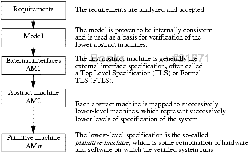
The hierarchy specification was written in the Hierarchy Specification Language (HSL). It identified the abstract machines of the hierarchy. The abstract machines were made up of sets of module specifications written in SPECIAL, as shown in the example that begins on page 522. Each abstract machine specification had one or more module specifications, each of which defined a group of related functions. Modules could be reused in one or more abstract machines.
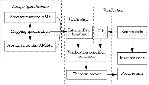
Mapping specifications defined the functions of one abstract machine in terms of the next higher machine. HDM module and mapping specifications were written in SPECIAL. Module and mapping specifications each had some unique constructs and a large set of common constructs. Several tools supported module and mapping specifications, including syntax checkers and consistency checkers.
A hierarchy consistency checker ensured consistency among the hierarchy specifications, the associated module specifications for each machine, and the mapping specifications between the abstract machines.
The basis for HDM implementation specification was the design hierarchy. The specification was accomplished by looking at each pair of consecutive abstract machines and the mapping between them. For each function in the higher-level abstract machine, programs were written to show how the function was implemented in terms of calls to the lower-level abstract machine. These programs were to be written in a high-order language that had a compiler. To verify these programs, a translator mapped the program into a Common Internal Form (CIF) that the HDM tools understood. Such a translator existed for a restricted version of Modula. Using the mappings, the two levels of specifications were translated into an intermediate language. This language, together with the CIF, generated verification conditions to be sent to the Boyer-Moore theorem prover. Assuming that the lower-level machine worked as specified, the higher-level machine was verified to work correctly. Given the correspondence of the CIF to the real programs, correctness of the CIF implied correctness of the real implementation. See Figure 20-2.
The implementation specification and verification parts of HDM were never used outside the research environment, nor was the originally planned design verification in HDM. The approach centered on the proof that the top-level specification correctly implemented a set of predefined properties within a model. The original intent was to be able to provide design verification for a wide variety of models and properties, but the difficulty in formally stating properties other than those found in U.S. Department of Defense (DOD) policy limited the utility of this approach. HDM was used as a design verification package for the Multilevel Security (MLS) tool [341]. This tool implemented a version of the Bell-LaPadula Model known as the SRI model and processed SPECIAL specifications for consistency with the model properties.
The SRI model differed from an implementation of the Bell-LaPadula Model in several aspects [992]. The SRI model was specifically constructed to function within the MLS tool. As a result, some entities differed from their Bell-LaPadula counterparts. Some entities had no counterparts. For example, the SRI model addressed visible function references and results (from VFUNs or OVFUNs), whereas the Bell-LaPadula Model did not have these elements. On the other hand, the Bell-LaPadula Model addressed discretionary access control and had a concept of current access triples as well as an access permission matrix. These entities did not appear in the SRI model. Both models had mandatory access control properties, and both called the mandatory rules the simple security condition and the *-property, but the rules differed slightly between the two models. Subjects were implicitly defined in the SRI model (as the invokers of functions). They were explicitly defined in the Bell-LaPadula Model. In the Bell-LaPadula Model, the *-property was expressed in terms of allowable access, but in the SRI model, that property addressed downward flow of information. Thus, they were not the same [992].
The SRI model embedded in the MLS tool has three properties.
The information being returned by a specific function invocation could depend only on information at a security level lower than or equal to that of the subject.
The information flowing into a state variable (VFUN) could depend only on other state variables that had security levels lower than that of the first state variable.
If the value of a state variable was modified, the modification could be done only by a function invocation whose level is the same as or lower than the level of the state variable.
The underlying model of the MLS tool was a reasonable interpretation of the multilevel policy of the U.S. Department of Defense. It was used successfully for several years to analyze the mandatory access control properties of systems and products.
The MLS tool processed a SPECIAL specification that described the externally visible interfaces to the SPECIAL model, as shown in Figure 20-1. When the MLS tool was used, one abstract machine was represented, and there were no mappings, but there might have been multiple modules in the specification. The SPECIAL module checker had to verify each module, and the hierarchy consistency tool had to verify the set of modules.
The MLS tool generated formulas that claimed the correctness of the three properties listed above. This was done for each function separately. All formulas assumed that the initial conditions and local assertions of the function were true and hypothesized the correctness of the applicable SRI model property. Exceptions from visible functions and function returns from OVFUNs and VFUNs were considered return values and thus generated formulas asserting the correctness of property 1 for each return value. For properties 2 and 3, the MLS formula generator identified new value assignments for state variables. For each such reference, the tool generated formulas asserting the correctness of properties 2 and 3. The formulas generated were called verification conditions (VCs). The MLS tool automatically submited the VCs to the theorem prover. The theorem prover attempted to prove the theorems. It reported those VCs that passed and those that failed or could not be proved. This information was fed back to the MLS tool.
The Boyer-Moore theorem prover [141] was a fully automated program. It did not have an interface for commands or directions to the theorem prover to take user-defined actions. The user had to provide any theorems, axioms, lemmata, and assertions that were needed to assist in the proof process. These were expressed in a LISP-like notation. For example, when proving VCs from the MLS tool, the theorem prover needed fundamental axioms about the elements of the VCs, such as rules of transitivity, reflexivity, and antisymmetry of the partial ordering relationship between security levels (see Section 5.2). The MLS tool provided these axioms to the theorem prover.
This approach made it easier for the user to prove simple theorems but potentially more difficult to prove more complex theorems. The user needed to understand the underlying theory used by the theorem prover in order to structure input in such a way that the theorem prover could find a proof. The Boyer-Moore theorem prover maintained a file of previously proven theorems and axioms that it could use in future proofs. In spite of the limitations, this theorem prover was capable of complex mathematical proofs.
The theory behind the Boyer-Moore theorem prover used an extended propositional calculus. This was enhanced to support the needs of computer programs. The heuristics of the theorem prover were organized to find a proof in the most efficient manner. The prover then performed a series of steps on a formula in search of a proof. The fundamental steps were as follows.
Simplify the formula by applying axioms, lemmata, and function definitions. Other simplifications included rerepresenting the formula by converting it to a conjunction of if-free clauses.
Reformulate the formula by trading terms for equivalent terms that are easier for the theorem prover to process. For example, if a theorem involved the term x – 1 (x ≠ 0), the theorem prover would replace x by y + 1. The formula now contained the terms y and y + 1 rather than x – 1 and x.
Substitute equalities by replacing equality expressions with appropriate substitutions, eliminating the equality clauses. For example, if (EQUAL s t) appeared in the formula, we replaced t with s elsewhere in the formula and eliminated the equality.
Generalize the formula by introducing variables for terms whose roles have been completed.
Eliminate irrelevant terms from the formula.
Induct to prove theorems when necessary.
The first step was always simplification, which could have resulted in a conclusion of the proof process by reducing the formula to “TRUE” or “FALSE”. If a conclusion was not reached, the theorem prover attempted the next step. If this did not result in a conclusion, processing returned to the simplification step. Processing iterated between simplification and reformulation until a conclusion was reached, or simplification or reformulation did not produce additional changes to the formula. The prover then attempted equality substitution, and if a conclusion was not reached, it returned to the simplification step and the process was repeated. In this way, the theorem prover iterated between simplification, reformulation, and equality substitution until a conclusion was reached or actions were exhausted. The prover might have split off subgoals at any step, and these were addressed separately. After carrying out each step in the sequence, the prover returned to the simplification step and proceeded to the next step if nothing could be one on any previous steps. Thus induction was only carried out if a proof could not be reached via the other steps.
HDM had some limitations that were addressed in a new, enhanced version of the system called Enhanced HDM, or EHDM. The fundamental framework of HDM was preserved but was enhanced to work more smoothly and with less complexity for the user. Like HDM, EHDM used modules as the building blocks of specifications. It supported multiple abstract machines and mappings between them and had an MLS tool for design verification. Like HDM, EHDM supported implementation verification. The difficulties with HDM focused on three areas: the language SPECIAL, some of the tools, and limitations of the theorem prover.
SPECIAL, which had been designed as a stand-alone specification language before HDM was developed, was not defined in terms that the Boyer-Moore theorem prover could readily use. This was attributable in part to the richness of the language and in part to the lack of specific constructs needed by the theorem prover. The missing constructs made formula generation and proof difficult. As a result, the toolset lacked a general-purpose verification condition generator to create verification conditions from SPECIAL that the Boyer-Moore theorem prover could use. Finally, the theorem prover itself was not interactive, requiring the user to understand the underlying theory used by the theorem prover in order to structure input in such a way that the theorem prover could find a proof.
To remedy these problems, new language constructs were needed. Eventually SPECIAL was eliminated as the specification language for EHDM, and a new language was developed. The new language bore many similarities to SPECIAL but was much more powerful. It had the rich, expressive capabilities of SPECIAL but had more logical constructs, allowing for more reusable specifications and proofs. The new language used the concepts of AXIOM, THEOREM, and LEMMA, which helped make it more conducive to the use of a theorem prover.
The HDM theorem prover was not interactive. The user had to understand the underlying theory used by the theorem prover in order to structure input so that the theorem prover could find a proof. The EHDM theorem prover was based on the Boyer-Moore theorem prover but was interactive. The MLS tool that worked with EHDM was one of the formal verification tools approved by the National Computer Security Center (NCSC) for use in high-assurance evaluations of computer products (see Section 21.2.3).
This discussion of the Gypsy Verification Environment (GVE) and its language Gypsy is based on the work of Cheheyl et al. [191]. GVE focused on implementation proofs rather than design proofs, and the verification system attempted to prove a correspondence between specifications and their implementation. It was also possible to use the GVE to prove properties of Gypsy specifications. The GVE was based on structured programming, formal proof, and formal specification methods. It supported a set of tools that included a Gypsy language parser, a verification condition generator, and a theorem prover.
Gypsy was a program description language and combined specification language constructs with a programming language. Using Gypsy, specifications could be added to program code at appropriate places in an implementation program. Alternatively, Gypsy could be used as an abstract specification language, using abstract types and their operations.
Gypsy was based on the programming language Pascal [522], with some notable changes. The primary goal of the language was verifiability, to include both formal proof and runtime validation. This fundamental requirement led to the following limitations on the Pascal language base. Gypsy routines could not be nested, but instead could be grouped together in a named “scope.” There were no global variables in Gypsy. Only constants, types, procedures, and functions were visible between routines. This helped to eliminate side effects from functions. Only constant parameters were allowed, and these parameters could be passed only by reference. Furthermore, Gypsy did not allow routine names to be passed as parameters. The data types in Gypsy were different from those in Pascal. Pointers were replaced by dynamic structures consisting of sets, sequences, mappings, and buffers, allowing for a variable number of components and three basic operations (addition, deletion, and moving a component to a different structure). Finally, statements were slightly different from Pascal statements, to support optimal placement of assertions.
A second goal of the Gypsy language was to support incremental development. A Gypsy program was made up of small, independently verifiable units including functions, procedures, lemmata, types, and constants. The units were defined so that they could be removed and replaced easily. They also supported verification. The proof of a unit depended only on the external specifications of those other units it referenced.
Gypsy provided facilities for detection, isolation, and recovery from hardware and software faults. It supported concurrency by allowing the security properties of concurrent routines to be specified and verified.
Gypsy also included an extensive set of specification constructs. Gypsy external specifications defined the effects of a routine, function, or procedure on its parameters at specified points in its execution. Gypsy provided keywords and specification statements for this purpose.
Entry: conditions that were assumed to be true when the routine was activated
Exit: conditions that must have been true if the routine exited
Block: conditions that must have held if the routine were blocked waiting on access to shared memory
Gypsy internal specifications addressed the internal behavior of a routine. These specifications could not be accessed outside the routine. The keywords and specification statements were
Assert: conditions that had to be satisfied at a specific point of execution
Keep: conditions that had to remain true throughout the execution of the routine
Gypsy supported the execution of lemmata as separate units. These lemmata defined a relation among a number of functions and global constraints. Lemmata could be used to state algebraic properties of abstract data types.
Gypsy provided a hold specification, which defined a constraint on the value set of the concrete representation of an abstract data type.
At the expressive level, specification statements were made up of boolean expressions that had to be true as specified by the keywords (listed above). For example, an expression with the entry keyword had to be true at the time the routine was activated. The boolean expressions were made up of constants, variables, and function references allowed in the program code. Gypsy also supported existential quantifiers using the keyword some, and universal quantifiers using the keyword all. Like SPECIAL, there was a mechanism to distinguish the old value of a variable from the new, so that the exit specification could describe the computed value of a variable parameter in terms of its prior value. Each expression in a specification statement also could contain a validation directive, which determined if the condition were to be proved during verification, validated at runtime, or both.
The GVE was not intended as a design verification package but rather as an environment for proving properties of implementation programs. However, MITRE developed a tool of the same nature as the HDM MLS tool that performs security flow analysis on specifications written in a limited subset of Gypsy.
The Bledsoe theorem prover was an interactive natural deduction system that used an extended first-order logic. This logic allowed subgoaling, matching, and rewriting. In order to prove a Gypsy program unit by inductive assertion, every loop had to be broken by at least one assert specification. Thus, there was a finite number of paths through the program that covered all possible execution sequences. Each verification condition was a theorem corresponding to a single path. The condition stated that the specification at the beginning of the path implied the specification at the end of the path. An analyst could guide the theorem prover, or the theorem prover could be instructed to choose the next step.
Many formal verification systems are being developed and used. We present a sampling of three: the inductive proof system called the Prototype Verification System, the model checker called the Symbolic Model Verifier, and the cryptographic protocol verifier called the NRL Protocol Analyzer. These three examples demonstrate the key concepts underlying each type of verification system.
The Prototype Verification System (PVS) [792] builds on the successes and failures of other systems developed at SRI, International. HDM and EHDM focused on providing a means of proving programs correct and supporting a full life cycle of program development. PVS was built as a “lightweight prototype” to explore the next-generation verification system based on EHDM. PVS provides mechanically checked specifications and readable proofs but does not attempt to be a full development methodology. There is no concept of successive layers of abstraction or mappings between levels as in HDM and EHDM.
PVS is a system for writing specifications and constructing proofs. It focuses on creating good specifications and proving appropriate properties for critical systems. PVS consists of a specification language that is tightly integrated with a powerful theorem prover. The theorem prover is highly interactive, allowing the user to guide the proof, and is often referred to as a “proof checker.” The use of powerful inference tools allows the enrichment of the language. Conversely, several of the features of the language, including data types, predicate subtypes, and dependent types, contribute to the effectiveness of the inference mechanisms used in the proof checker. PVS also includes tools such as a syntax checker, a type checker, and parsers.
The PVS language is a strongly typed language based on first-order logic. It is used to construct compact specifications. This language is especially designed to describe computer systems but, like SPECIAL, is generally nonprocedural, focusing on what is to occur and how it is to be accomplished. This highly expressive language supports modularity by allowing the specifier to describe theories, which are somewhat similar in concept to the modules in SPECIAL. The typing of the PVS language is rich and includes the notion of a predicate subtype as well as type constructors for function, tuple, record, and abstract data types.
Each theory contains a series of statements called declarations. The declarations identify types, constants, variables, axioms, and formulas used by the theory. Theories are reusable, and many have been incorporated into the PVS package. These predefined theories have been named preludes. A PVS library provides a wealth of such preludes. They include fundamental definitions and theorems of set theory, functions, relations, and ordering, as well as the properties of the integers and the real numbers. External PVS libraries provide finite sets, bit vectors, coalgebras, real analysis, graphs, quaternions, lambda calculus, and linear and branching time temporal logics.
The PVS proof checker uses a life cycle concept with four phases.
Exploratory phase: The specification is debugged. The developer tests the specification proofs and revises key high-level proof ideas.
Development phase: The developer constructs a proof in larger steps and works on the efficiency of the proof.
Presentation phase: The proof is honed, polished, and checked.
Generalization phase: The developer analyzes the proof and the lessons learned for future proofs.
The PVS proof checker is highly interactive, supporting a goal-directed proof search. The prover starts from the conclusion and progressively applies inference steps to generate subgoals. The prover repeats this process until the subgoals are trivially provable.
One goal is to support efficient development of readable proofs in all stages of the proof development life cycle. The PVS prover has a small set of powerful primitive inference rules and a mechanism for composing rules into proof strategies. It can also rerun proofs and check that secondary proof obligations (such as type correctness conditions) have been met. Among the PVS proof checker primitive inference rules are the folowing.
Propositional rules, such as a cut rule for introducing case splits, a rule for lifting if-conditionals to the top level of the formula, and a rule for deleting formulas from a goal (weakening rule)
Quantifier rules, such as a rule for instantiating existentially quantified variables with terms
Equality rules, such as replacing one side of an equality premise by another
Other rules introduce lemmata, axioms, type constraints, and decision procedures to limit the number of cases.
Proof strategies are frequently used patterns of proofs that have been composed into single steps. Examples of proof strategies are propositional simplifications, use of decision procedures, and rewriting with a definition or lemma.
PVS has been used in a variety of applications in many areas, not just computer security. NASA centers have analyzed requirements for several spacecraft projects and for avionics control. PVS has been used to verify microarchitectures as well as complex circuits, algorithms, and protocols in hardware devices. PVS has been used successfully to analyze both fault-tolerant algorithms and distributed algorithms. The model checker integrated into the PVS theorem prover enables PVS to analyze finite-state systems. Finally, PVS has also been used in real-time and hybrid systems, for compiler correctness, and in other applications.
The Symbolic Model Verifier (SMV) [158] is based on Control Tree Logic (CTL) [199]. Control Tree Logic (see Section 34.3) adds eight temporal connectives to those of the predicate calculus. Two letters represent each connective. The first is an “A” or an “E.” Intuitively, one can think of “A” as inevitability, or meaning “along all paths.” “E” is called possibility and means “along at least one path.” The second symbol is “X,” “F,” “G,” or “U.” An “X” refers to the next state, an “F” means some future state, “G” means all future states (globally), and “U” means “until.” Therefore, “AX” means “along all possible next paths,” and “EX” means “there is at least one next path.”
CTL can represent a model specifying a system as a directed graph whose nodes represent the states. The propositional atoms of the system that hold in that state can be indicated within the graph of the node, and the possible state transitions are represented by arrows connecting the appropriate nodes.
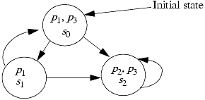
EXAMPLE: Suppose that M is a model that specifies a system with three states s0, s1, and s2 and three propositional atoms p1, p2, and p3. Suppose further that the possible state transitions are s0 → s1, s0 → s2, s1 → s0, s1 → s2, and s2 → s2. Finally, suppose that p1 is true in state s1, p1 and p3 are true in s0, and p2 and p3 are true in s2. The graph in Figure 20-3 completely represents this model.
We can unwind this graph, creating an infinite tree of all computational paths beginning in a given state. This provides a graphical representation that clarifies the new temporal connectives such as “AX” and “EX.” See Figure 20-4.

An SMV program specifies the system and includes a description of the properties to be verified. The property specifications are written as CTL formulas. The SMV tool processes the program and returns either a “true,” indicating that the specifications hold for all initial states, or a trail of actions to help in debugging.
The SMV program may consist of several modules. The module called main takes no parameters and identifies the modules of the program. This module forms the root of the model hierarchy. It is the starting point for building the finite-state model for a given description. Individual module specifications contain declarations describing a set of variables. A module may be parameterized and may contain instances of other modules. Alternatively, a module can be reused as necessary.
The SMV program may have many types of declarations. The VAR declaration defines a variable and identifies its type. The language supports boolean, scalar, and fixed array types, as well as static structured data types. The ASSIGN declaration assigns initial and next values to variables. Next values are described in terms of current values of other variables, as in SPECIAL and Gypsy. The DEFINE declaration assigns values to variables in terms of other variables, constants, logical and arithmetic operators, and case and set operators. The INVAR declaration describes an invariant on the state transition system. The SPEC declaration introduces a CTL specification of the properties to be proved about the module.
The SMV language includes other features. One of the more interesting is a set of fairness constraints that can be used to rule out infinite executions. It describes deterministic and nondeterministic transitions as well as specifying synchronous or interleaving composition.
The SMV model checking tool uses the proof logic of CTL. The proof technique is to establish semantic equivalence of the premises (from the specification of the system) and the conclusion, represented by the properties following the SPEC declaration in the CTL program.
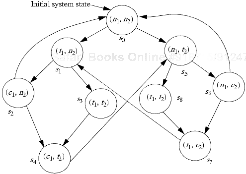
EXAMPLE: Suppose that two concurrent processes share a resource but must not have access to it at the same time. To ensure correctness, we must define a critical section of each process' code and a protocol to determine which process can enter its critical section at which time. We verify our solution by confirming that some expected properties are met.
The model M is defined as follows. Let p1 and p2 be two processes. Define each of the following states for each process pi.
A noncritical state ni corresponding to the process not attempting entry
A state ti in which the process is trying to enter the critical section
A critical state ci corresponding to the process being in its critical section
A process moves from its noncritical state to trying to enter its critical state to being in its critical state to back to its noncritical state, and so on. The set of possible system states is (n1, n2), (n1, t2), (n1, c2), (t1, n2), (t1, t2), (t1, c2), (c1, n2), (c1, t2), and (c1, c2). However, the state (c1, c2) is not included in the model because it is the condition that the model is to show is not possible. We also model the (t1, t2) state twice in our model, as shown in Figure 20-5. Both occurrences record that both processes are in their trying states, but s3 describes p1's turn and s8 describes p2's turn.
Suppose that the properties we want to show about the model are as follows.
Safety: Only one process at a time can be in the critical section.
Liveness: A process trying to enter its critical section will eventually do so.
Nonblocking: A process can always request to enter its critical section.
The model for this system is represented by the graph in Figure 20-5. Consider each of these desired properties separately.
Safety: In terms of the model, this property requires that, for all paths, c1 and c2 cannot be true simultaneously. The CTL formula is AG¬ (c1 ∧ c2). Because the state (c1, c2) is not defined in our model, this formula trivially holds.
Nonblocking: In terms of the model, this property requires that, for every computational path, every state ni has a successor state ti. The CTL formula is AG(ni → EXti). Inspection of Figure 20-5 shows that this is true.
Liveness: In terms of the model, this property requires that, for all paths, if ti is true, then there is some future state (on the same path) in which ci is true. More simply, if the first process attains its trying state, then it will always eventually reach its critical state. The CTL formula is AG(ti → AFci). This proof can also be verified by inspection of Figure 20-5.
Thus we have verified that all three properties hold.
SMV has been used to verify sequential circuit designs [157]. SMV was used to verify the IEEE Futurebus+ Logical Protocol Specification [172]. Researchers also used SMV and some of its predecessors to verify security protocols [200], finite state real-time systems [171], and concurrent systems [199].
The Naval Research Laboratory (NRL) Protocol Analyzer (NPA) [690] is a special-purpose verification system used to verify cryptographic protocols, including authentication protocols and key distribution protocols. The NPA is written in Prolog [201]. It is based on the term-rewriting model of Dolev and Yao [307]. This model assumes that an intruder can read all message traffic, modify and destroy any messages, and perform any operation (encryption or decryption) that can be read, altered, or performed by a legitimate user. The model further assumes that there are certain words, such as keys or encrypted messages, that the intruder does not already know. The intruder's goal is to learn these words, and the defender's goal is to prevent the intruder from doing so.
The NPA approach to protocol verification is based on an interaction among a set of state machines. The user specifies nonsecure states and attempts to prove that they are unreachable. The proof uses an exhaustive backward search from the unreachable state. The NPA can also use proof techniques for reasoning about state machine models and for finding flaws and identifying potential attacks as well.
The NPA Temporal Requirements Language (NPATRL) is the fundamental language of the NPA. It expresses generic requirements of key distribution or key agreement protocols.
The work in protocol verification includes the development of protocol specification languages and tools for generating formulas and searching for proofs. Each method has its own language. The large number of protocol verification systems led to the development of CAPSL, the Common Authentication Protocol Specification Language. CAPSL is a high-level language for cryptographic authentication and key distribution protocols. This allows a protocol to be specified once, after which, theoretically, translators can be provided to convert the specification automatically into another language supported by a protocol verification system.
A CAPSL specification has three parts. The protocol specification describes the protocol. A types specification describes the encryption operations. An environment specification provides scenario-specific details that can help in finding a proof for a protocol.The NRL Protocol Analyzer has a CAPSL interface [142].
Formal verification begins with a specification stated in an appropriate language. The language has a precise syntax and well-defined semantics based on mathematical principles. The system design and the properties to be verified are described in formal specifications. The specification of the design is proved to meet the specification of the properties. The proof may use general, inductive techniques or be tied to a specific model, in which case model checking techniques are appropriate.
The Hierarchical Development Methodology (HDM) was an early formal verification technique. It treated the specification as a hierarchy of abstract machines. The requirements and model were first proven consistent internally and with one another. The model was mapped into the top-level abstract machine, which in turn was mapped into the next lower abstract machine, and so forth. Each layer was expressed in terms of the lower layer, and each mapping between machines was verified to be correct. A later version, called Enhanced HDM (EHDM), used a different specification language and an interactive theorem prover to verify the system.
A second early verification environment focused not on verifying design but on proving properties of implementations. It combined a specification language with a programming language. The specifications were embedded in the programs. It supported incremental development as well as handling of hardware and software faults.
The Prototype Verification System (PVS) evolved from EHDM. Its goals are to provide a system for proving theorems about specifications. It does not attempt to support the full life cycle of program development. Specifications written in PVS use a specification language coupled with an interactive theorem prover. PVS has been used successfully to analyze requirements for spacecraft and to verify protocols in hardware devices.
The Symbolic Model Verifier (SMV) is a model checking tool. It represents a model of the system in a specification language. The properties to be verified are written in CTL, a temporal logic. An automated program tests the model against properties to verify that the properties hold. Circuit designs, security protocols, and real-time systems have been verified using this methodology.
Protocols, especially cryptographic protocols, are notoriously difficult to get right. The NRL Protocol Analyzer is a system used to verify protocols. It is a state-based analysis engine that determines whether the protocol can enter states labeled as nonsecure. It can also identify potential attacks.
One area of research is how to define, and how to select, security properties in a way that is amenable to formal analysis and applies to realistic situations with precision. Security properties are often defined at an abstract level, and the mapping of the properties to that level removes much of the detail that affects security at the implementation level. Furthermore, many security-relevant properties are difficult to analyze in the context of formal methods. The issue of noninterference, for example, falls outside most formal analysis methods that operate on implemented systems. A good counterpoint is the analysis of cryptographic protocols. Formal methods work well with cryptographic protocols because the protocols can be expressed mathematically and the implementing software is small, but the current methods do not scale well to large systems.
This suggests restructuring of systems to make formal verification of security-critical components easier. Developing architectures that lend themselves to formal verification is a deep area. The concept of reference monitors comes into play, but in most instances systems are simply too large to structure as single reference monitors. How can systems be architected to achieve a compact or simple enough form so that formal methods can be used to verify the key components?
Expressions of security properties, designs, and implementations can simplify the use of formal methods. Different environments and different uses lead to different verification methodologies. Currently, there are many languages that can express policies at various levels of abstraction and others that can tie code to specifications. Can one create languages that support the implementation of verified designs without introducing flaws that create vulnerabilities?
In the realm of security and safety, ongoing work includes verification of cryptographic protocols and verification of code on active networks. The latter is particularly critical because active networks change the software that controls traffic while the network is in use. Protocols supporting these changes, and the code being introduced, must meet security requirements that are suitable for the network, but the verification of the code must be done at the time the code arrives, and so must be quick. How to speed up the verification of code is an important issue. The ideas of proof-carrying code (see Section 22.7.5.1) may work well in this environment. This is an important area of research.
McLean [686] provides a terse but enlightening review of 20 years of formal methods. Snow [941] discusses the future of assurance, including the role of formal methods. Wing [1051] discusses the relationship of formal methods and security. Bowen and Hinchley [136, 137] discuss guidelines for and misperceptions of formal methods.
Many other specification languages are available. Among these are ACL2 [555], Estelle [1007], HOL [411], LOTOS [129], SDL [1007], and Z [299]. Comparisons of these languages are instructive [37, 45].
Similarly, several model checkers are in use. In addition to SMV, the model checker Spin [481] is based on a temporal logic system and FDR2 [848] is based on a process algebra. SyMP [80] is a tool that combines model checking and theorem proving in a single framework.
Many papers discuss formal methods and tools for protocol analysis. Kemmerer [559] laid the basis for this work. The Interrogator [707, 708] is another Prolog-based protocol analysis system. Kemmerer, Meadows, and Millen [560] contrast three protocol analysis systems. Abadi and Needham [2] present 11 principles for creating cryptographic protocols.
1: | Add a SPECIAL specification to the example beginning on page 522 that describes get_access (see Section 5.2.4.1). |
2: | Section 20.3.1.1 presents three properties of the SRI model as embedded in the MLS tool. Compare and contrast these properties with the simple security property and the *-property of the Bell-LaPadula Model. |
3: | Why does the Boyer-Moore theorem prover perform induction only when the other five steps fail to simplify the formula? Why does it not try induction first? |
4: | Contrast the goals of the Gypsy Verification Environment with those of HDM. In particular, when is using HDM appropriate, and when is using Gypsy appropriate? Can HDM and Gypsy be used interchangeably? |
5: | Add rules to the rats example for PVS in Section 20.4.1.1 for exponentiation (^) and remainder (%). Remember that 00 and the remainder of anything when divided by 0 are both undefined. |
6: | Compare the life cycle concept that the PVS proof checker uses with the waterfall model of software engineering (see Section 18.2.2). Can the life cycle concept be expressed as a form of the waterfall model? |
7: | Consider the example in Section 20.4.2.2. The proof of the nonblocking condition states that “for every computational path, every state ni has a successor state ti.” But the path s0s1s2 is a cycle in which n2 never changes to t2. Reconcile this observation with the statement in the proof that “Inspection of Figure 20-5 shows that this is true.” |
[1] Huth and Ryan [503] define a reactive system as one that is not meant to terminate. Examples include operating systems, embedded systems, and computer hardware.
[2] In the language of PVS, “not equal” is actually written as “/=”; we use the more intuitive “≠” here.