CHAPTER 7
DRIVE SYSTEM
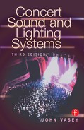
The drive system consists of the audio components in the audio chain, which drive the amplifiers once the signal has left the mixing console (Figure 7–1).
GRAPHIC EQUALIZER 
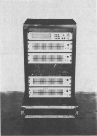
The graphic equalizer consists of 27 potentiometers (pots) or faders that are on third-octave centers from 40 to 16,000 Hz (16 kHz). These controls enable the sound system to be tuned to suit a given environment. Tuning is a subjective operation that requires considerable experience and skill. Listen closely to any equalizing with an analyzer and let your ears be the final judge. Each side of a stereo sound system requires a graphic equalizer, and it is the first component in the drive chain (Figure 7–2). A digital graphic equalizer offers the facility to store and recall settings. The use of digital equalizers makes the process of system equalization more efficient by allowing quick comparisons between settings.
CROSSOVERS
The crossover, or frequency dividing system, divides the signal into two, three, or four separate bandwidths. The crossover allows control of the level fed to the amplifiers that drive the low frequencies, mid frequencies, and high frequencies, respectively. A fourth bandwidth may be acquired for sub-low octaves. The crossover frequencies depend on the type of speaker system. The slope between each frequency band at the crossover point is generally 24 dB per octave.
The crossover points on a three-way active speaker system with additional sub-low cabinets would have the following bandwidths:
1. Sub-low cabinets, 20 to 63 Hz. The sub-low cabinets can be used as part of the entire speaker system and tuned with the other frequency bands or used independently with signal fed from an auxiliary send from the mixing console. When the sub-low cabinets are used as part of the entire speaker system, some crossover units feed a mono sum of the left and right stereo inputs.
2. Low-frequency bandwidth, 20 to 250 Hz.
3. Mid-frequency bandwidth, 250 to 1,200 Hz. The mid-frequency band varies depending on the type of mid-range cabinets. The range of the mid band may vary between 250 and 1,000 Hz to 250 and 4,000 Hz.
4. High-frequency bandwidth, 1,200 Hz and up. The crossover point of the mid range determines the high-frequency crossover point.
Figure 7–2. Graphic equalizer. This piece of equipment enables tuning of the sound system to suit the environment.
Some crossover units have phase correction and can correct phase errors that occur in the loudspeakers and cabinets. Phase alignment should begin at the highest-frequency band. All other frequency bands should be adjusted in sequence from highest to lowest. If after an initial adjustment further adjustments are needed on any frequency band, all lower bands require adjustment to compensate. To set phase alignment accurately, use an analyzer to provide a pictorial view of the crossover regions and set phase controls for the flattest response. A sine wave from a signal generator at each crossover point can be used. Alter the phase control for minimum volume, then switch the polarity switch to invert one of the outputs to achieve true summation (Figure 7–3).
Some crossovers also feature time alignment, which delays some band-widths to keep the source from all band-widths the same.

Figure 7–3. Crossovers divide the signal into two, three, or four separate bandwidths.
LIMITERS
After the signal leaves the crossover it passes through a limiter, a device that limits the amount of signal reaching the amplifiers to avoid distortion or damage. The threshold of the limiter is set to the input voltage of the amplifiers being driven. The ratio should be infinite for maximum protection. Some crossovers are equipped with limiters inserted halfway through the filter network to avoid frequency shifting problems associated with the more normal end of line limiting.
DRIVE MULTICORE CABLES
Drive multicore cables distribute the outputs of the drive system to the amplifiers. Figure 7–4 shows the rear of a drive rack. Generally there is a multicore cable for each side of a stereo system. Because all the multiway cables are strapped together, the drive cables end up on one side of the system, usually on the basis of where the monitor console is situated. A cross-stage drive cable distributes the signal to the amplifiers on the opposite side. The common standard of drive-cable color coding is white for the left side and red for the right side.

Figure 7–4. Rear of a drive rack. Drive cables connect to the rack with multipin connectors.