
CHAPTER 12
MICROPHONES AND DIRECT BOXES
Microphones convert acoustical energy into electrical energy.
TYPES OF MICROPHONES 
A dynamic microphone has a diaphragm in a strong magnetic field. Sound waves that strike the surface of the microphone cause the coil to move in the magnetic field. The movement generates a voltage that corresponds to the sound pressure on the surface of the diaphragm.
A condenser microphone (Figure 12–1) involves electrostatic principles rather than the electromagnetic principles of a dynamic microphone. A condenser microphone has a diaphragm placed adjacent to a backplate, and capacitance varies with sound pressure. Condenser microphones sometimes require a pad between the diaphragm and the microphone preamplifier.
A C-ducer microphone is a sensing tape with preamplifier and power supply. Because the C-ducer is flexible, it can be affixed to the curved surfaces of instruments such as a harp or guitar (Figure 12–2).
A ribbon microphone has a thin metal ribbon suspended between the poles of a magnet to sense sound pressure.
A pressure zone microphone (PZM) uses the pressure zone at an acoustical boundary to eliminate distortion problems common with other microphones. The active element in a PZM is a pressure-calibrated electret capsule mounted so that it faces the boundary and lies within the pressure zone. All incoming sound is received indirectly, free of distortion caused by phase interference (Figure 12–3).

Figure 12–1. Microphone patterns. (Courtesy Shure Bros.)
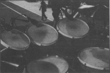
Figure 12–2. Microphones on a drum kit.
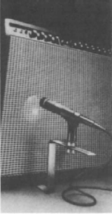
Figure 12–3. Microphone on an amplifier. (Courtesy Shure Bros.)
A hypercardioid lavaliere microphone, an Isomax microphone is extremely small and can be positioned in otherwise inaccessible areas.
A radio microphone, which incorporates a standard microphone into a radio transmitter, has limiters between the microphone and the transmitter to keep the signal from overloading the transmitter. Developments with wireless systems have given performers the opportunity to be considerably more mobile than with hard-wired microphones and at an affordable price. The use of a multiple radio microphones is becoming more common; multichannel systems with antenna distribution are used.
A wireless microphone consists of three main components: an input source, a transmitter, and a receiver. The size of antennas is directly related to the wavelength (and inversely proportional to frequency). Lower radio frequencies require larger antennas; higher frequencies require smaller antennas. Antennas should be maintained to achieve maximum performance from the system line of sight between transmitter and receiver. The distance between transmitter and receiver should be kept to a minimum. It is preferable to use long audio cables to get the signal from the receiver to the sound system than to transmit over long distances or use long antenna cables.
DIRECT BOXES
The direct box, also known as a DI (direct injection), matches the impedance of an instrument to the input impedance of a mixing console. An active direct box has a transformer and a circuit powered by batteries or the phantom power supply. A passive direct box has only a transformer and provides no boosting for low-level signals. The direct box can be connected to any high-impedance instrument such as an electrical bass or synthesizer. Some instruments provide a balance-line output for direct connection to mixing consoles (Figure 12–4).
MICROPHONE PLACEMENT
For live concerts most microphones are positioned as close to the source as possible. The closer the microphone, the stronger is the signal, the less spill there is from other instruments, and the less chance there is of feedback. Microphone stands should be as rigid as possible so that they do not stray from the set position. Condenser microphones are more delicate than dynamic microphones, but all must be treated with care to maintain their quality (Figure 12–5).

Figure 12–4. Schematic of an active direct box. (Courtesy Yamaha Music.)
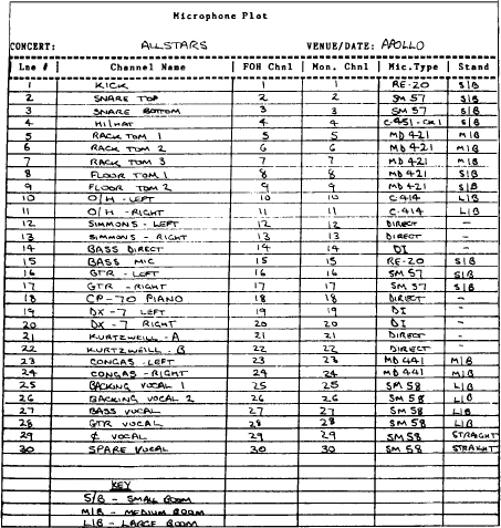
Figure 12–5. Microphone patching list. The patching list identifies input location and designation, type of microphone, microphone stand, and any additional electronics to be patched into the channels of the front of house and monitor consoles.