CHAPTER 8
HOUSE MIXING CONSOLES
The several different types of front of house (FOH) mixing consoles all perform the same basic function to control the level, tone, and output designation of all console inputs (microphones, effects, tapes) and follow similar signal paths. The more sophisticated a console, the more functions it can perform and the more facilities it has available for complex applications (Figure 8–1).
INPUT CHANNEL 
The following is a step-by-step explanation of all functions on an input channel in the order the signal follows.
INPUT
The input is connected through an XLR female socket on the rear panel of most consoles. This can be a microphone or direct box connected to a multicore line, tape machine, or effect return.
MICROPHONE OR LINE SWITCH
This switch selects between a low-impedance input such as a microphone or direct box and a high-level, line-level input such as a tape machine or effect return.
![]()
Figure 8–1. Input module of a front of house console. (Courtesy Yamaha Music.)
INPUT GAIN
Input gain controls the amount of level a channel accepts. These controls can be a fully variable pot or a switch with several fixed values.
PAD
The pad alters input gain but only by specific amounts. It is used in conjunction with the input gain control for precise adjustments.
PHASE REVERSE SWITCH
The phase reverse switch reverses input polarity, a feature useful for correcting the phase cancellation caused when two microphones are very close.
GROUP SELECT SWITCHES
The group select switches assign channel output to the group-mixing buses or directly to the main stereo output.
EQUALIZER SECTION
The equalizer section controls channel tone. The two types of equalization are peaking and shelving.
PEAKING.
Select the center frequency and cut or boost the Q (bandwidth), which is either fixed or variable, around the selected frequency. A frequency of 1,600 Hz allows gain control of higher and lower frequencies. The bandwidth between the lowest and the highest frequency can be adjusted on some consoles from a broad band to a narrow band. Parametric equalizers provide control of the bandwidth.
SHELVING.
The frequency selected determines the point at which everything above or below it will be cut or boosted. A low shelf (160 Hz) allows all frequencies below 160 Hz to be cut or boosted. A high shelf (5 kHz) allows all the frequencies above 5 kHz to be cut or boosted.
HIGH-PASS FILTER
The high-pass filter allows all frequencies above the filter frequency to pass and attenuates all frequencies below it. The amount of attenuation usually is between 12 and 18 dB per octave. Use high-pass filters to reduce the rumble picked up on stage that discolors the desired sound.
EQUALIZER ON AND OFF
Some consoles have a switch to bypass the equalizer for comparison before and after equalization.
INSERT POINT
The insert point in the channel, normally after the equalizer and before the fader, is where limiters, noise gates, or other devices are inserted into the channel through insert jack sockets mounted on the rear panel above the input or on jack fields on the front of the console.
AUXILIARY SENDS
Auxiliary sends often are labeled echo send or foldback send and provide discrete outputs from the channel. Some consoles have a switch to designate the send either prefader, whereby the control operates independently of the fader, or postfader, whereby the output depends on the fader. Auxiliary sends can be used for effects sends, sub–low cabinet sends, and monitor sends back to the stage, among other things.
PAN POT
Pan controls select channel position in the left and right dimensions for stereo application. The pan pot also is used to assign mono groups on some consoles.
PREFADE LISTEN SWITCH
Prefade listen (PFL), also called cue or solo, selects the channel to the headphone output and cue meter. This allows you to listen to that particular channel independently of the fader.
PHANTOM POWER
The phantom power switch supplies 48 V to power condenser microphones and direct boxes. The 48 V flows down both balanced audio lines, that is, pins one and two; zero reference is at the shield of the cable (pin one). Phantom power does not pass through a transformer. A reading of 48 V between pins one and two and between pins one and three is needed if phantom power is to power microphones and direct boxes.
MUTE SWITCH
The mute switch turns on the channel. The PFL function still operates with the channel off on most consoles.
FADER
The fader sets the level sent to the channel's output to assigned groups and the auxiliary sends switched to the postfade position.
VOLTAGE-CONTROLLED AMPLIFIER CONTROLS
Voltage-controlled amplifiers (VCAs) allow gain to be adjusted with external DC voltage. They are more useful than faders are because the audio signal can go directly to the main outputs, shortening the path of the signal through the mixer and reducing the risk for signal degradation. The VCA controls look like those of faders except that the DC control voltage, not the signal, passes through the control. Grouping channels with the VCA master controls allows the level of the assigned channels to be adjusted without any accumulated noise. Because the VCA master controls only signal level, not signal destination, the channel must be assigned through the group select switches.
MUTE ASSIGN
A mute assign switch allows a master switch to mute groups of channels assigned to a mute master.
OUTPUT
The output section provides master level control for groups, auxiliary sends, and VCA masters (Figure 8–2).
The matrix allows the different console outputs to be grouped as required to provide the desired balance. Several matrix outputs are available for different combinations for different destinations, that is, main stereo speaker systems, delay systems, center fills, and tape machines. Auxiliary returns accept the signal from line-level units, effects, and tape players.
TALKBACK MODULE
The talkback module, which differs on all consoles and may have some or all features, can contain an oscillator for calibrating the console and the entire sound system. It also may have a switch and microphone input that can be assigned to all the groups and to the talkback output, which can be connected to the monitor console to feed through the monitors for on-stage instruction for equipment and sound checks. Some modules have a feature for intercom, headphones, and microphone systems for communicating with the stage (Figures 8–3 and 8–4).
![]()
Figure 8–2. Master module of a front of house console. (Courtesy Yamaha Music.)
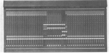
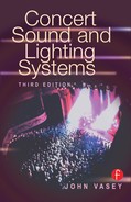
Figure 8–3. Front of house console. The many different types of front of house consoles all perform the same basic functions. (Courtesy Yamaha Music.)
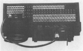
Figure 8–4. Rear panel of a front of house console. All connections to the console are made in the rear panel. (Courtesy Yamaha Music.)
POWER SUPPLY
The power supply for the mixing console usually is a separate unit. This keeps the transformers, which convert AC input into DC voltages to drive the electronics, away from the console. The normal voltages supplied to the console from the power supply are + and –18 to 20 V to drive the electronics, 48 V for the phantom power, and additional voltage for meter lamps, console lamps, and VCA control (Figure 8–5).
GAIN STRUCTURE
The gain structure (Figure 8–6) is the relations among all the components in the signal chain. It should be set so that the console output, graphic equalizers, and crossovers correspond. Do this by using a tone to set channel input level, crossover levels, and amplifier levels to zero. What the output meters show on the console is exactly what amplifier output will be. The best way to run the console is to have adequate headroom available for transient peaks without residual noise. An input signal that is too high distorts both channel and console output, affecting all input. The input must be set to a reasonable level with the input attenuator. It is pointless to turn down the crossovers or amplifiers if the console is overloading. Instead, have some headroom on the system and keep the console input gains down. Leave enough headroom for live music, because transient peaks need room to move to avoid distortion, blown components, and generally bad sound.

Figure 8–5. Mixer power supply. This usually is a separate unit from the mixer. (Courtesy Yamaha Music.)
CONSOLE CARE
Consoles must be kept clean with regular dusting; accumulation of dust destroys console components. Never use spray cleaners. Pots and faders can become noisy if they become dusty or dirty. Spray cleaners only exacerbate the problem by removing their lubricating film along with the dust. Cover a console when it is not in use to reduce its exposure to dust.
MIXING
Mixing is not something to learn from a book. Although you must understand the equipment being used, the room acoustics, and the material being performed, mixing is an art that builds on knowledge and experience. There are a number of steps to take to keep the sound system under control and sounding good.
Most important is gain structure. Ease your way into a mix; do not start with everything running flat out. Be careful to retain enough headroom for soloists and vocalists. Always start the sound check with the rhythm section, then check the melody instruments, and then the vocalists and soloists. Build the mix on the foundation of the rhythm. It is pointless to have the drums and bass so loud they drown out everything else.
Try to keep the sound dynamic so that it has some life and is not just a wall of noise. It should be possible to pick out each instrument and differentiate it from others being played. Beware of overequalizing, or you will end up trying to tune each instrument to fit in with others rather than letting them fit in naturally. If a drum keeps ringing, no matter what you do with the equalizer, the answer may be to have the drum tuned properly or move the microphone. The drum tone may have the same frequency as a resonant frequency in the room.
Check all microphone positions before starting a sound check to correct, if necessary, microphone position, proximity to other microphones, source of the sound being miked, and fittings and stands.
Make effects complement the music, not confuse it. Subtle reverberations can enhance the sound, and loud repeats can be used for dramatic effects.
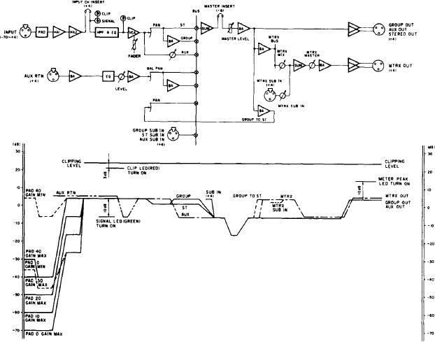
Figure 8–6. Mixer gain structure. (Courtesy Yamaha Music.)
The level of the sound depends on the type of music, the environment, and the available power. A highly reverberant room, in which all the low frequencies are subject to large amounts of room gain and the higher frequencies are absorbed, requires a different approach than an open field or a room with minimal reverberation.