
Good day, dear readers! Now we’re here at Chapter 2 of our book. This chapter covers the topics related to modeling tools and features of Blender. I’ll also be discussing a bit about some basic stuff for beginners of Blender so they can follow along without difficulty.
So, let’s get started!
Blender Preferences

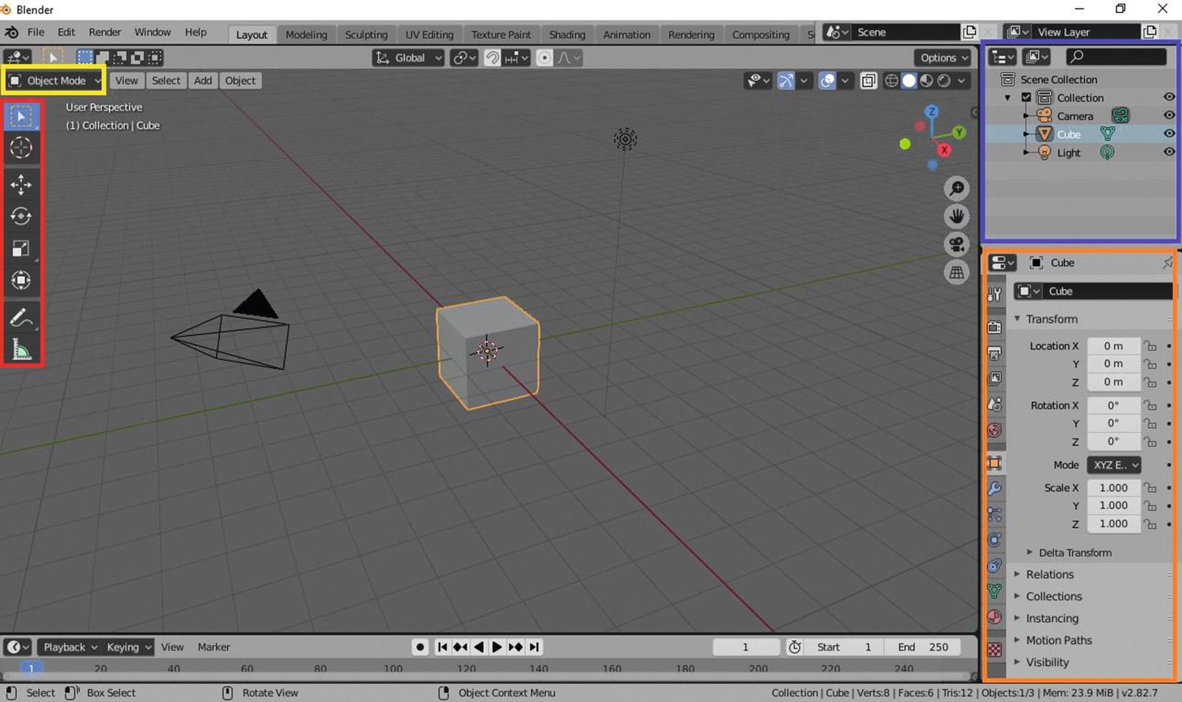
Blender 2.82: Layout Workspace(Red:Tool Setting; Yellow:3D viewport, Orange:Properties;Green: Outliner)
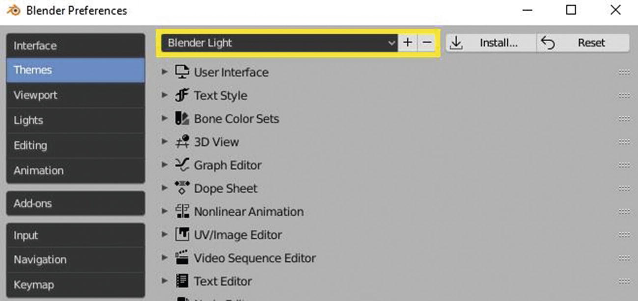
Blender Preferences
This Blender Preference appears as a new small window after you click preference in the edit menu. You can also add your own edited theme here by clicking the plus icon beside the select menu and deleting an existing theme by clicking the minus icon.
Now let’s discuss one of the basic things that we need to review before digging into an advanced lesson: workspaces.
Workspaces
Workspaces are essentially predefined window layouts. You can also create your own workspaces by clicking the plus icon beside the sculpting workspace tab. Workspaces help you create your project with ease since they are already set up for different projects like modeling, animating, sculpting, texturing, shading, rendering, etc. For this chapter, since our focus will be on modeling, I will discuss the layout workspace and modeling workspace, which are both helpful in modeling aspects.
Layout Workspace
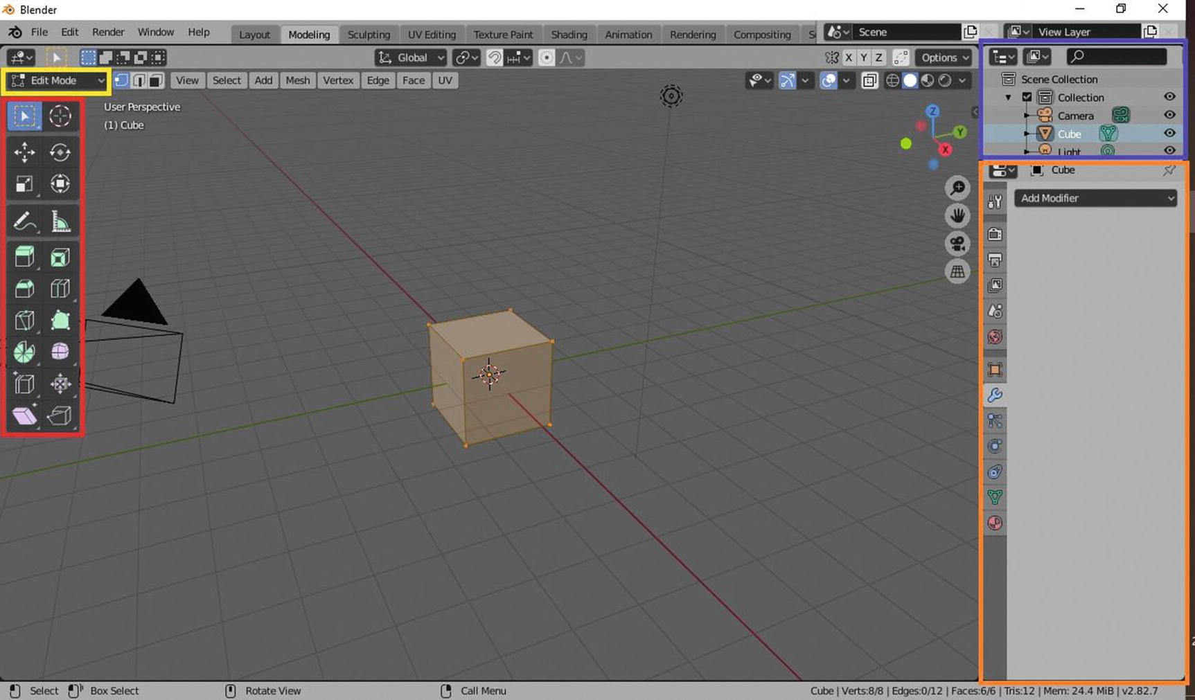
Modeling Workspace
You can see that I put a rectangle in the four parts of both workspaces. These four parts will be used the most so I want to at least give you an overview of these four. The first one, the one in the yellow rectangle, is the select menu for modes. These modes change the setup of the 3D viewport (the large area where you saw your object), to help you easily apply your ideas. The one in the red rectangle is the toolbox where, of course, your main tools can be found. We will discuss more about it soon so just sit tight. The one in the blue rectangle is the outliner where you can see your objects listed. You can change their names through the outliner or even delete the object, just like how you can change your layer name or delete your layer in Photoshop. I’m sure you know how to use Photoshop. What? You don’t know? Okay then, as you can see, beside the orange icon, there are names like cube, camera, and light, right? If you double-click it using the left mouse button (or left touch pad button for laptop users), you will see the name highlighted, a sign that you can already change its name. If you do a right-click using your mouse button (or right touch pad button for laptop users), a drop menu will pop up that contains a selection for copying or deleting the selected object.
You can also hide the object in the viewport by toggling the eye icon beside the name. You also hide it in the rendering process by toggling the camera icon, which by default isn’t enabled in outliner. You can enable it in the filter select menu, which is beside the search menu that can be found at the top part of the outliner.
By default, some parts of the outliner can’t be seen – the same with others like the toolbox and properties windows. You can adjust it by placing your cursor in the side (not in the edge) and dragging it.
Now we have two things needed in order to proceed in modeling: our 3D objects and our 3D modeling toolbox (I’m talking about the features of software specific to modeling stuff). Let’s start by discussing the objects.
The Objects
First of all, we need to know the objects present before we start modeling. There’s a lot of different types of objects in Blender, and not all of them can be edited for modeling. Objects have their own purposes, just like a paper and a pen. Some of them are just for creating a scene, like the lights and camera.
Let’s discuss the types of objects that Blender has so we will know its limits and capabilities; but before that, there are two ways of adding objects. The first way is to go to add menu ➤ and choose from the listed objects, and the other way is to hold Shift + A and choose from the listed options.
Mesh Objects
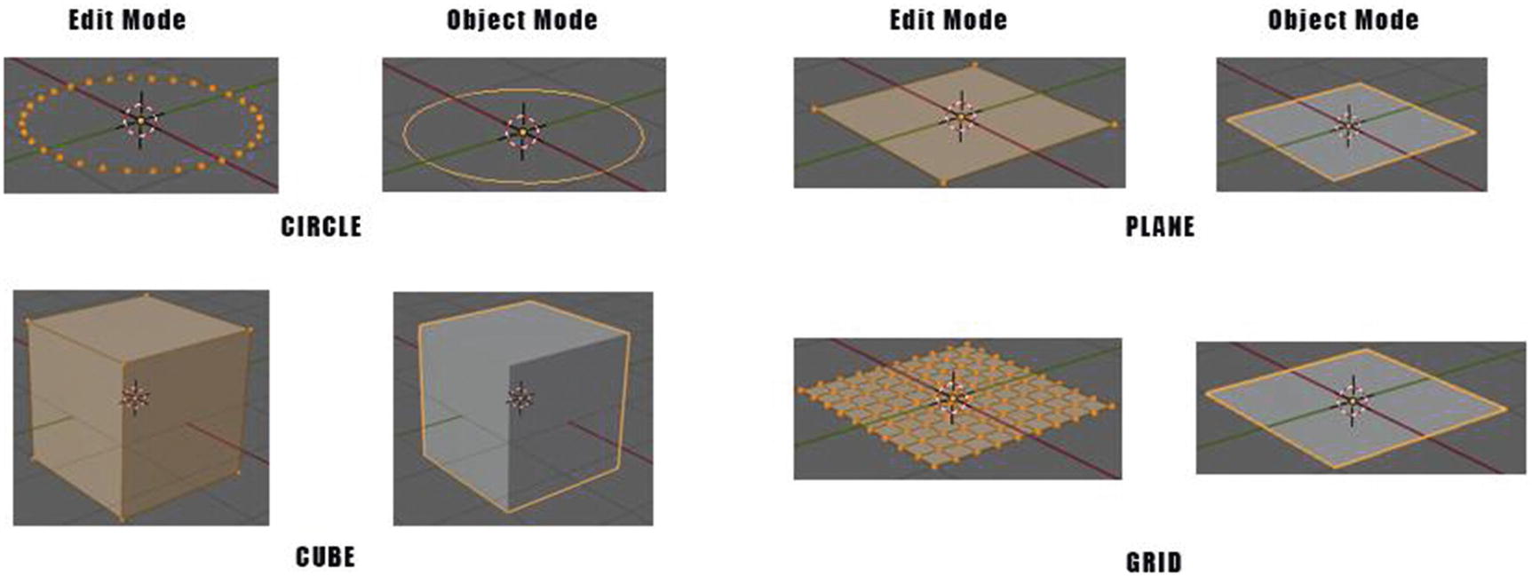
From the top left: Circle, Plane, Cube, and Grid
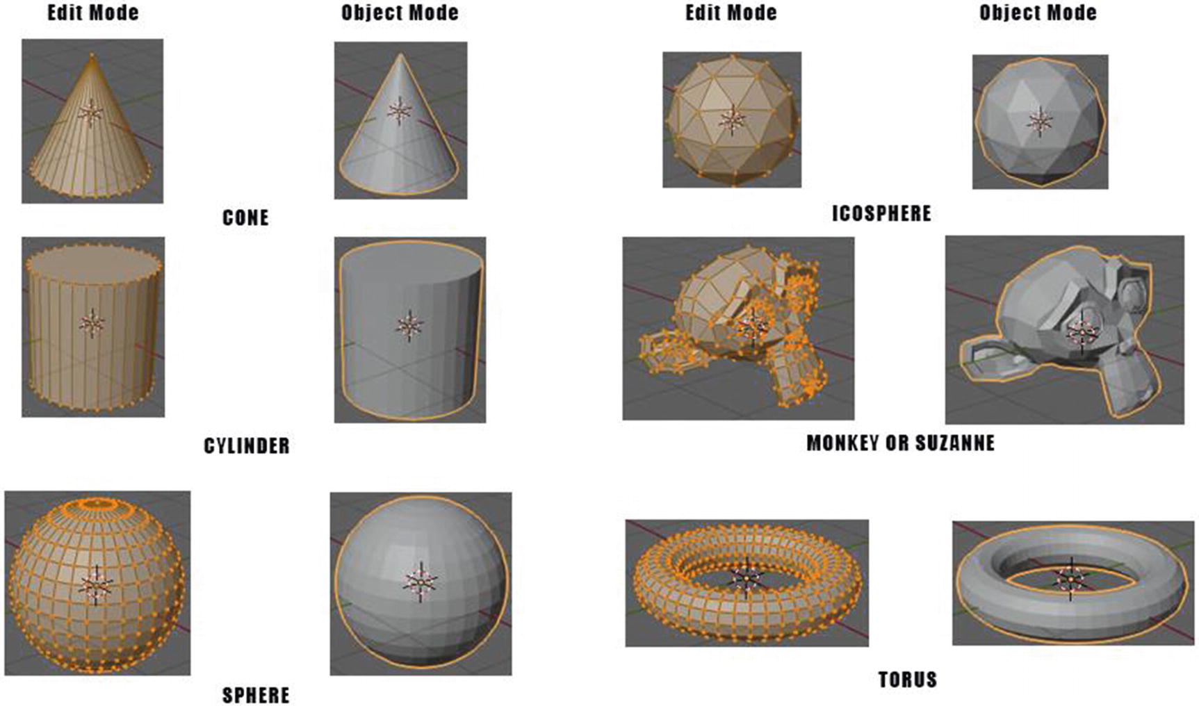
From the top left: Cone, Icosphere, Cylinder, Monkey, Sphere, Torus
What we have here are the following: Circle, Plane, Cube, Grid, Cone, Icosphere, Cylinder, Monkey or previously called Suzanne, Sphere, and Torus.
For our object circle, you can notice that when you look at it in object mode, it looks like just a thin circle line, which is similar to curve objects; but when you look it in edit mode, what you can see are vertices or dots, connecting a line or called edges, to form a circle.
This is how mesh objects are composed. Meshes are composed of vertices, which are the dots highlighted in orange that you can see in the edit mode, edges are the lines that form a face and faces, which are a the triangles or squares that form a mesh object.
In the case of a circle mesh object, it only has vertices and edges.
You can also notice that the plane and the grid have the same look when you view it in the object mode, but you can see its difference in edit mode.
Grid mesh object , unlike plane, is already divided in nine columns and nine rows. It was like a subdivided plane, ready for some basic modeling, like modeling a leaf.
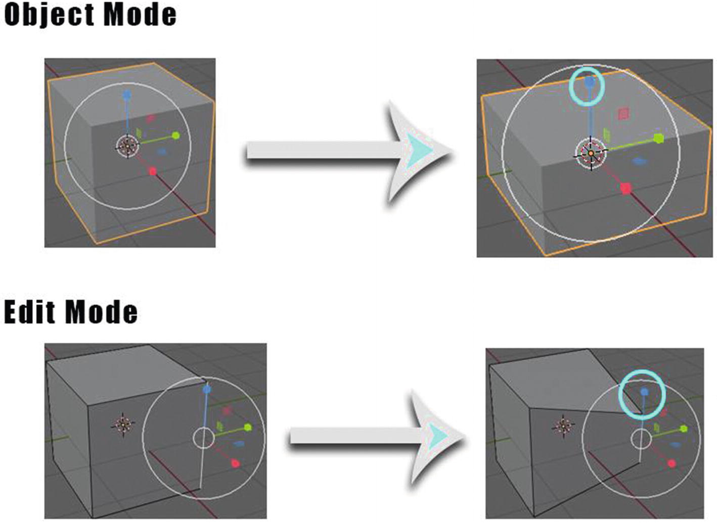
Scaling Object mode and Edit mode
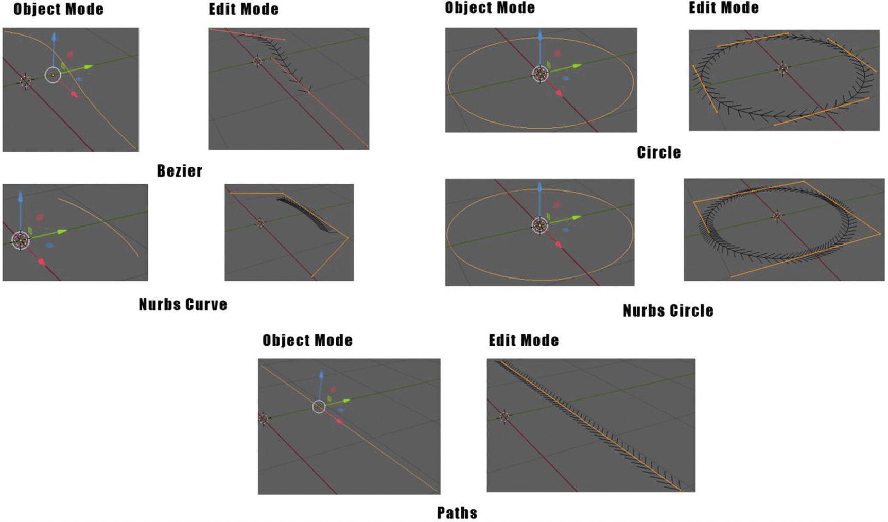
List of Curve Objects
I’d like to note that these modes are not only for mesh objects. They are also available in other objects, and other objects like armatures have their own modes.
Now let’s proceed to other objects.
Curve Objects
Curve objects are defined by control points and have two modes: object mode and edit mode. Take a look at Figure 2-8 to see the list of these types of objects.
As you can see in Figure 2-8, the circle in curve objects is the same in circle that you can see in mesh objects when you view it in object mode. You can also notice that the circle and nurbs circle here in curve objects look the same in object mode, but you can see its difference in edit mode, how its control points have been structured. It’s the same for the path. You might notice that in object mode, it looks like just a thin line but in edit mode, you can already notice its control points.
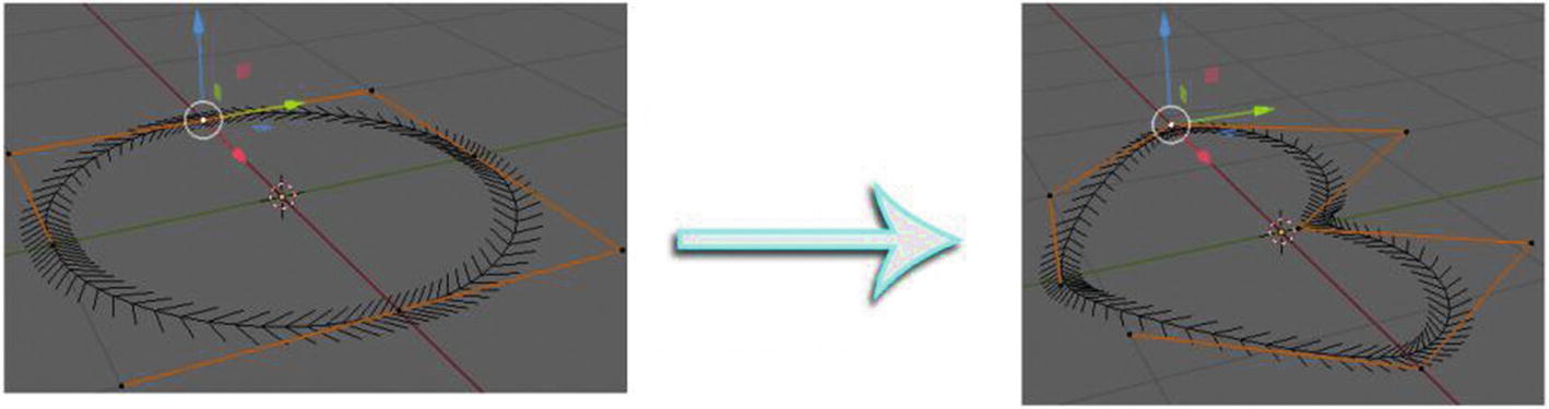
Nurbs Circle transformed into heart shape
Control points can help you easily transform the curve objects into the shapes you want to create, curve objects especially can be converted to mesh objects by the following steps:
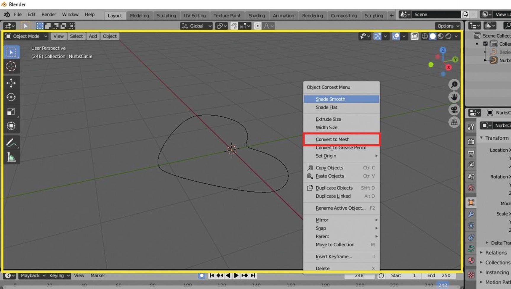
Object Context Menu (Yellow rectangle: 3D viewport)
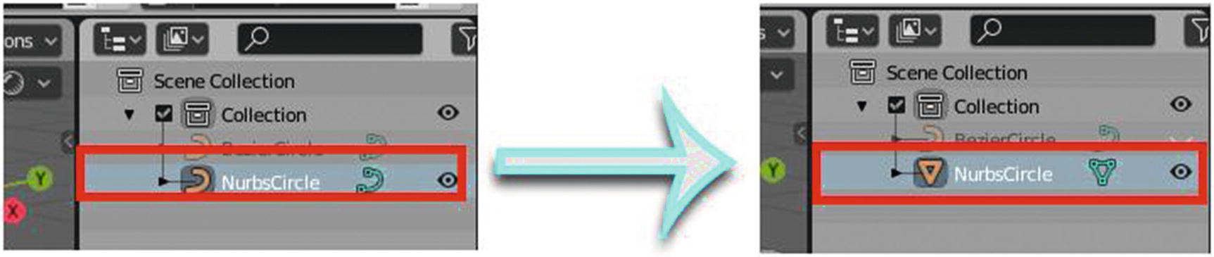
Convert to Mesh Icon in Outliner
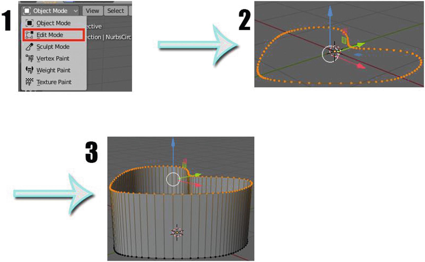
Modifying the Mesh converted from Curve object
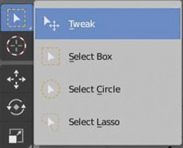
Select Tools
You can find these tools in both object and edit modes. In order for you to see these drop-downs, you need to hold click on the Select icon as shown in Figure 2-13. You can also access these tools by its shortcut keys: press B for Select Box, C for Select Circle, and L for Select Lasso.
We have different extruding tools in Blender, but we will discuss them separately. For now, let’s focus on the objects.
Let’s now proceed to surface objects.
Surface Objects
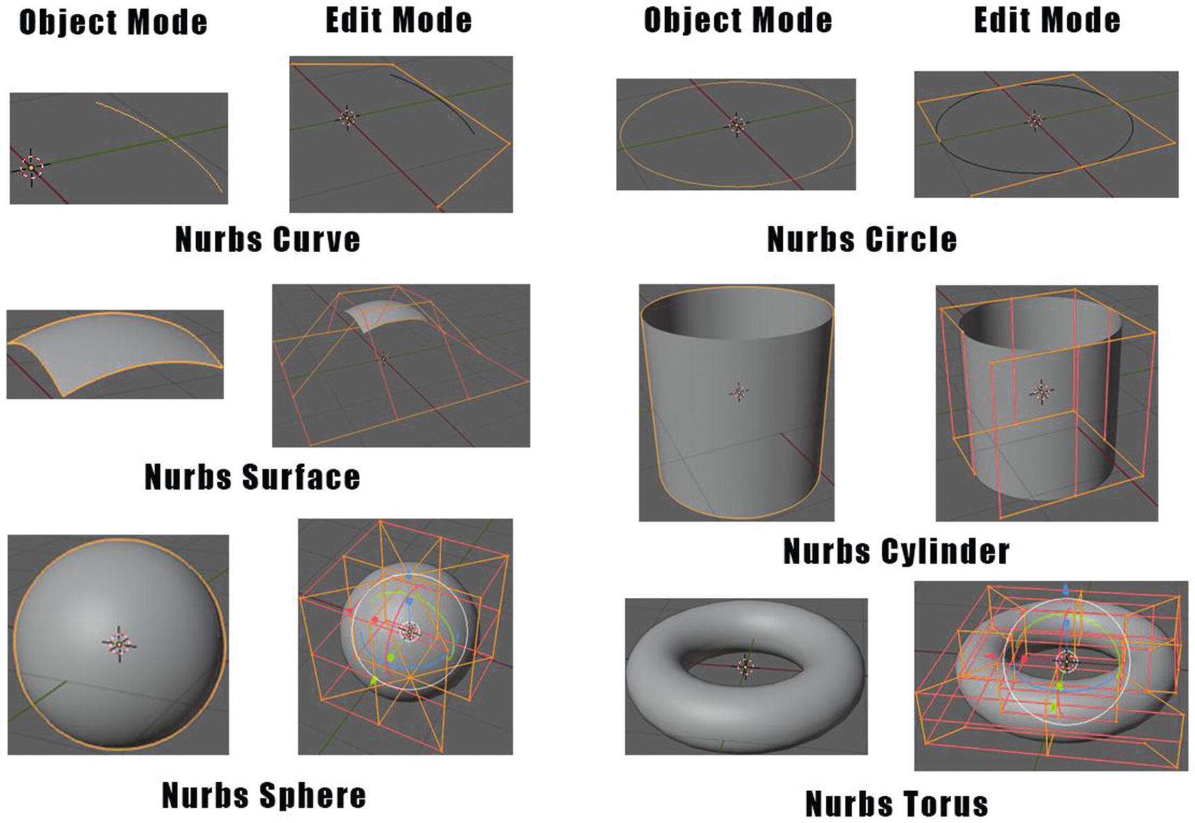
List of Surface Objects
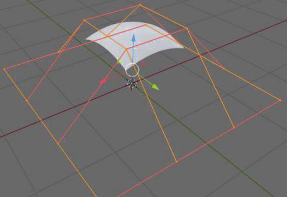
Nurbs Surface in Edit Mode (Layout Workspace)
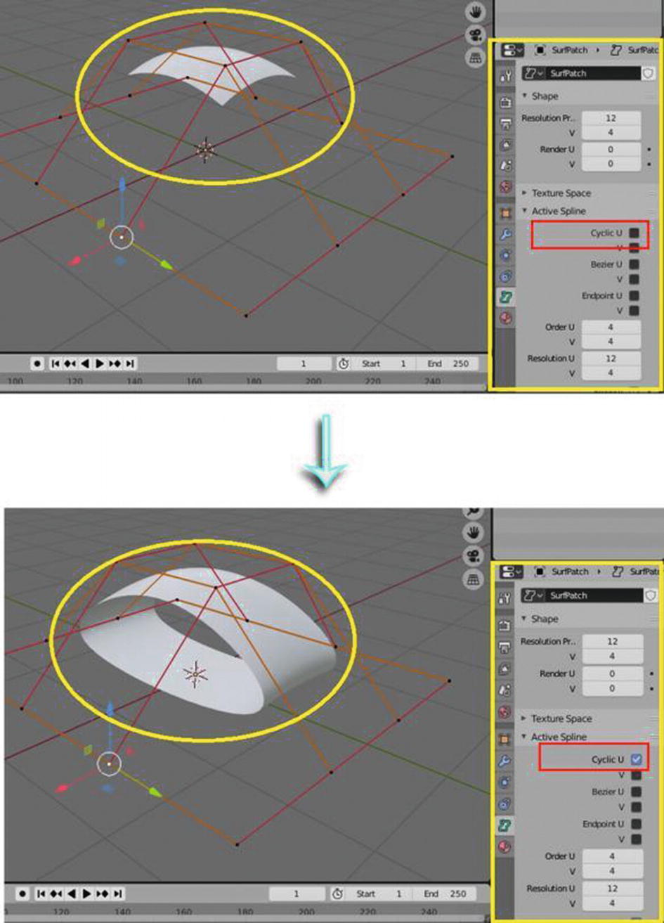
Nurbs Surface modified

Nurbs Surface sample output after modified
You might wonder how come in Figure 2-17, I have many segments or control points in the edit mode compared to previous figures. During the process, I subdivide the segments by going to Segments menu ➤ Subdivide, and it will subdivide the current selected segment/s. What I do to accomplish the abstract model is just by subdividing the segments three times and then scaling and moving the control points.
So now, let’s proceed to the next type of object, which is the metaball.
Metaballs Objects
A metaball, in my opinion, is quite complicated to use. The moment the two metaballs touch or get close to each other, they merge. Unlike our previous examples, metaballs are not defined by vertices (unlike meshes) and not by control points (unlike surfaces and curves). They are defined by a mathematical formula that is calculated by Blender. You can turn this to a mesh object, just like curve and surface, by going to Object Menu ➤ Convert To ➤ Mesh from Meta/Curve/Surf/Text. Metaballs have two modes: object mode and edit mode.

List of Metaballs
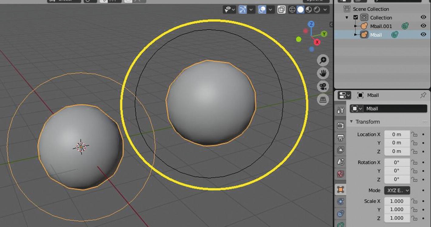
As you can notice, when in object mode, you can see one ring around the metaballs; while in edit mode, you can see two rings except in cube. You cannot see a ring, whether you’re in object mode or in edit mode. Well, when it comes to cube, its ring is hidden unless you edit something in edit mode, and then you will see these two rings appear. Okay. What are these rings for?
The ring that you can see in the object mode and the outside ring in the edit mode are called selection rings while the inner ring in the edit mode is called influence, which has direct control of the metaball’s stiffness.
You can also use metaballs for modeling like to form an initial shape of your model, streams, or water droplets.
Since metaballs can easily merge or blend to each other, they often work as a family of objects or groups. When it comes to this, you must know that there are already two or three metas (shortcut for metaball) merged together; the base meta is the one who determines the transformation, and resolution has the materials and textures or acts like a parent for the other metas. In order to determine which is the base meta, the one in which its object name is without a number, for example, we have the following: Mball, Mball.001, Mball.002; Mball is the base meta of the metaballs.

Adding the first metaball
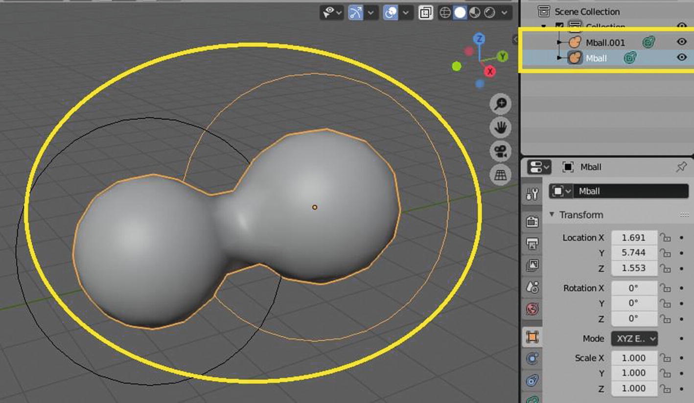
Adding the next metaball
You can notice that in our outliner, the first meta has the name Mball.

Deleted the Mball and the remaining Mball.001
Added new metaball
As I add a new metaball while the ring is in there, you can see that it automatically adds two metaballs. You can think of the rings around the metaballs as a container. If you want to delete the metas because you want to make some changes but you want to add them again, with the same number, just leave the rings there and add metaballs and voila! You will add a number of metaballs easily.
Now, let’s move on to the next object, which is the Text object.
Text Objects
Text objects are objects in Blender to create text. They have two modes: object mode and the edit mode. You can edit the default text of this object in the edit mode only. You can turn this object to mesh just like the curve, surface, and metaballs by going to Object Menu ➤ Convert To ➤ Mesh from Meta/Curve/Surf/Text and convert this to a curve object by going to Object Menu ➤ Convert To ➤ Curve from Mesh/Text.
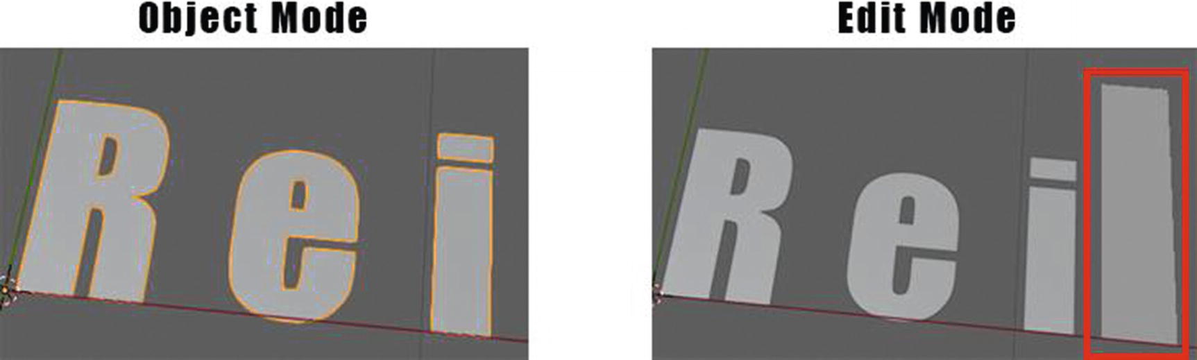
Text Object viewed in two modes
The one inside the red rectangle is the cursor, just like when you are typing in a regular document. In editing its fonts, I do it in the object data panel that can be found in the properties section.
Now, let’s proceed to the next object, which are the grease pencil objects.
Grease Pencil Objects
These are objects that can help you for your 2D ideas. Yes, 2D since you can already create a 2D scene or 2D animation in Blender. But depending on you, you can also use this for character modeling or even in designing game assets or game environments. These objects serve as a container of strokes that allow you to draw in a 3D space. These objects have five modes: Object mode, Edit mode, Sculpt mode, Draw mode, and Weight Paint mode.

List of Grease Pencil Objects
In empty object, if you look at it in both object mode and edit mode, by default, you can see it as literally an empty object. It shows our definition of a grease pencil, an object that serves as a container for strokes since when you go to draw mode and draw something on it, that’s the time you can see something in the empty object unlike in the stroke object and monkey object. But wait, if you notice in Figure 2-24, for the stroke and monkey, you can see a line inside the black stroke of the two objects.

Closer look at Stroke object in edit mode

Modifying Monkey object

Extruding Monkey object
As you can see in Figure 2-27, the ones that have been extruded are those in the sides because they were the ones with the points. The one in the middle, or the orange one, are a fill color for monkey that can be found in the object data panel under the properties section.
Okay. Let’s now proceed to the next object, which is the armature.
Armature Object
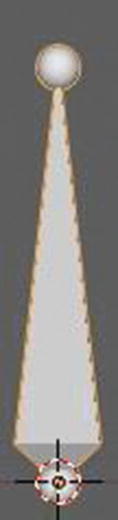
Armature object
You can only use this object for making poses animation. Games have characters. If you want to create your character and be the one to rig it, or have the bones for its animation, you can learn more about this armature object. Its tools lie mostly in pose mode and in the object Data panel under properties. It has a few tools in edit mode like extruding the bone.
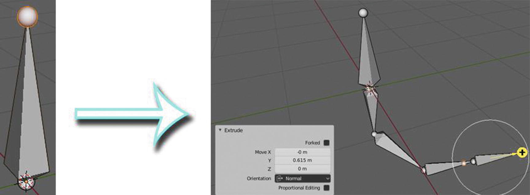
Basic modification for Armature object
As you can see, I just simply use extrude and the minimum of the rotate tool for modifying the armature or the bones. And yes, its shape is just like that.
Let’s now proceed to the next object, which is the lattice.
Lattice Object
Lattice objects only have object mode and edit mode. They have only basic editing tools. Then, what is the use of this object?

Lattice and how it works
There aren’t many available tools for editing or modifying lattice objects. Okay. You may ask, if this is for editing an existing object such as meshes, curves, surfaces, texts, and particles, why not just directly edit or modify those objects in edit mode instead of using the lattice? Well, here’s a reason you will consider using this. If your mesh object already has many vertices, it will be hard for you to modify it, especially if you only want to modify just a part of it. So here is the lattice to help you just select the part of that mesh and modify it smoothly. It can also allow you to edit multiple objects in a scene since objects are allowed to use the same lattice. It’s just like a container.
So now, let’s proceed to the next object, which is the empty object.
Empty Objects
Empties. Literally empty objects but they have a purpose. They might have no volume and surfaces, and just a single coordinate point with no geometry, but they have their own uses. Depending on the empty object characteristics, they have their own purposes. Some of them are useful for animation while some are useful for reference.
Empties can serve as transform handles too. They can also be parented to other objects, which gives you the ability to control a group of objects easily. They can be used as a target for constraints like bone. Lastly, they can also be used in an array modifier to help you move only one object by using this as the offset and to other modifiers like mirror, wave, displace, etc.
Don’t forget: since they don’t have volume or surfaces to edit on, they only have the object mode.
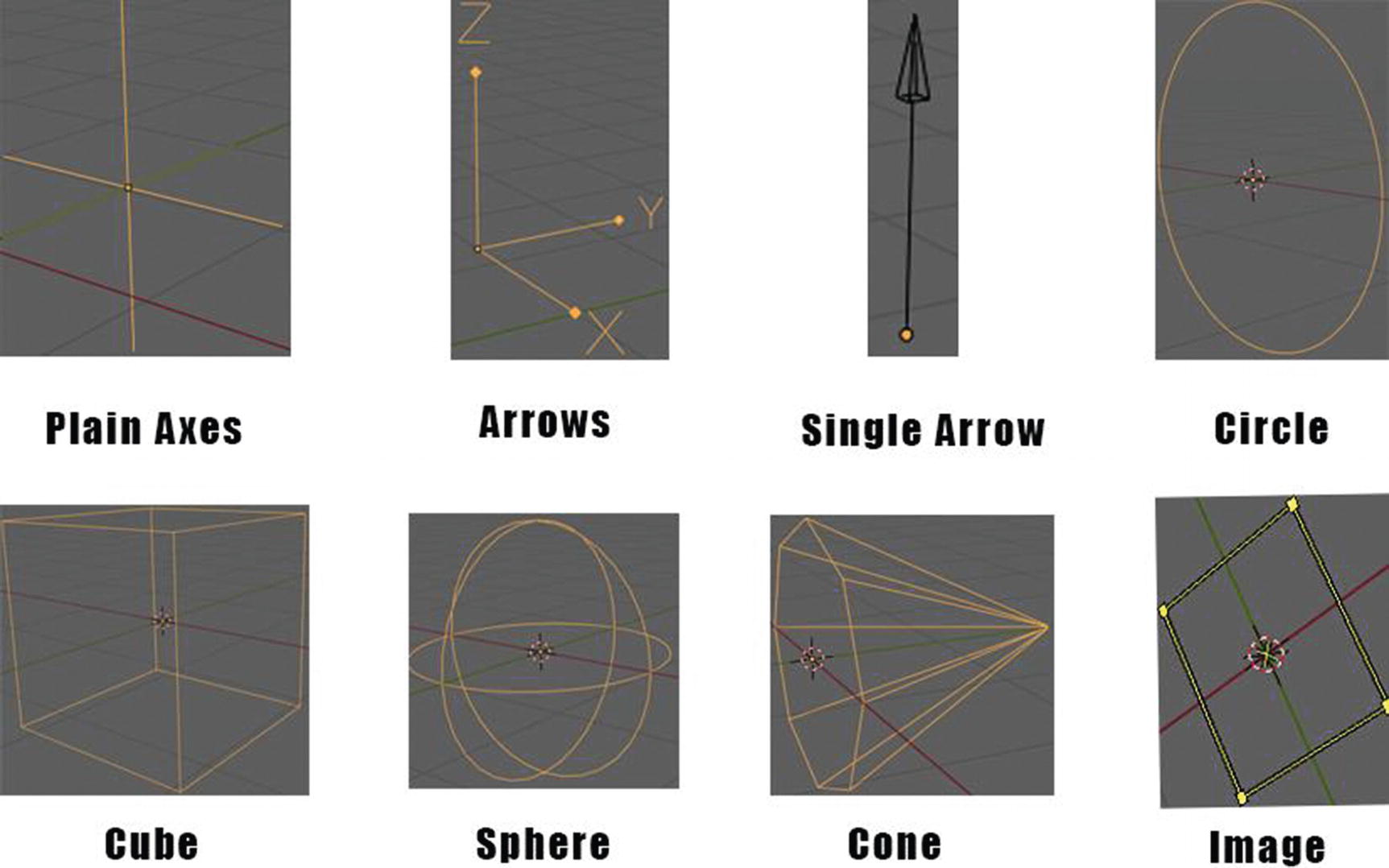
List of Empty Objects
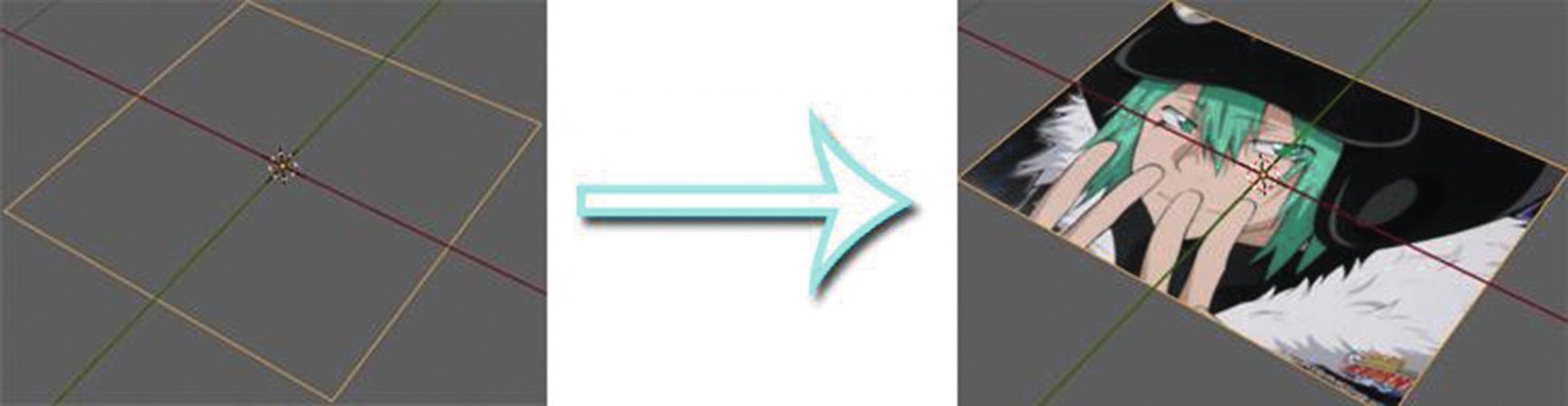
Image Empty Object works
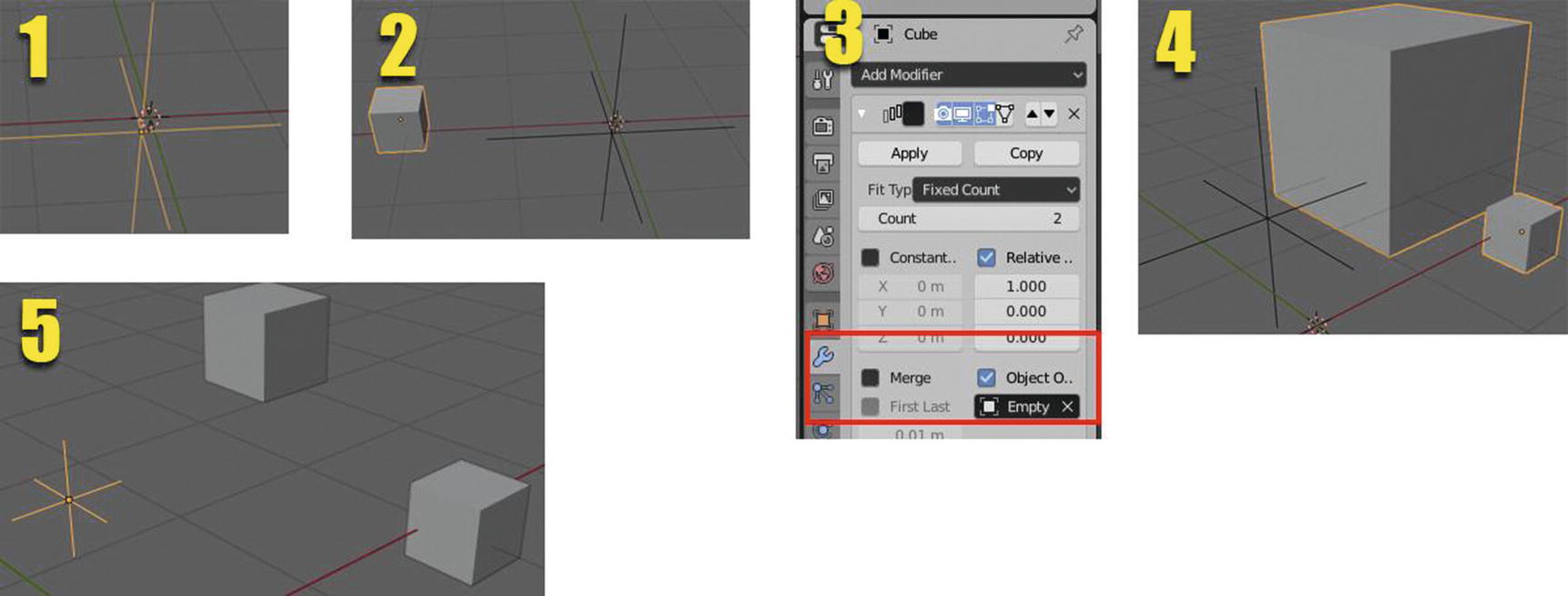
Plain Axes Empty works
I add the image by first adding an empty image, then going to the Object Data panel in Properties ➤ Image ➤ Open.
I used an array modifier for this example. I add the array modifier in the cube, then set it to empty in the object offset as you can see in number 3. As you can see in our example, in numbers 4 and 5, the plain axes affect the size of the added cube from the array modifier. As I scale the plain axes, the cube also scales down.
Plain axes, arrows, single arrows, circles, cubes, spheres, and cones are all empties that can be used in arrays, constraints, animations, and objects parenting. Their only difference is the effect on the base on their structure or how it can help you make your project easier than the other one. For example, the arrows can help you create a 360-degree camera effect easily by parenting an object to it, then animating the empty itself.
Note that you can drag and drop images into the scene to get these references into Blender.
There is another object next to empty, which is image, but it acts exactly like image empty so I will skip it and go to the next one, light objects.
Light and Light Probe Objects
As its name suggest, light objects give light to the scene. On one hand, we only have object mode for this type of object, and you can only edit some basic data from it through the object data panel in the properties, though you can do some scaling, moving, and rotating too. Light probes, on the other hand, record lighting information locally to light the scene using indirect lighting. Eevee used them as support objects.

List of Light objects and how they work
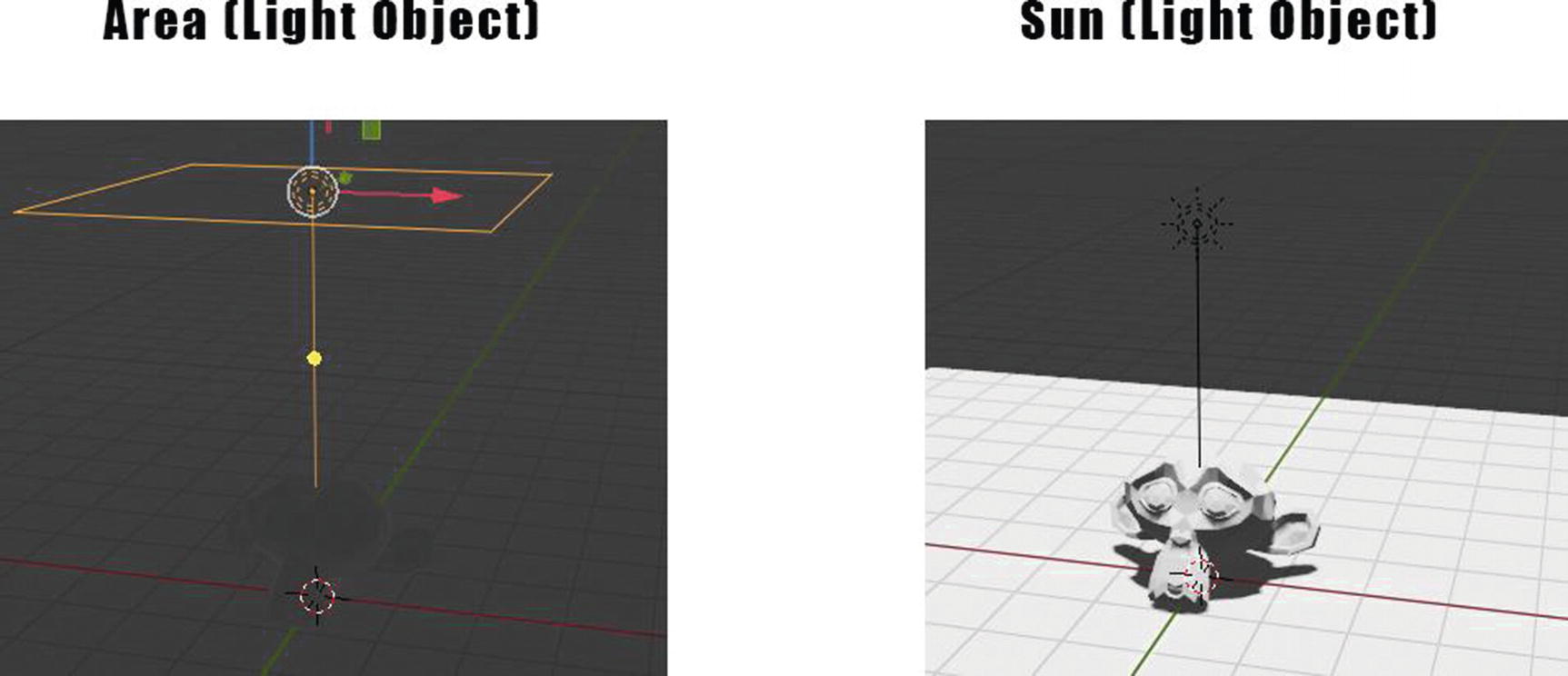
Area Light vs. Sun Light
This is because the sun lamp has a multiplier to account for the distance of the actual sun from the Earth and since the lighting system, especially in cycles, is physically accurate, you’d have to set the sun lamp to more than 1,000,000 and place it hundreds of thousands of miles away in the 3D world for it to be accurate.

List of Light Probes
Light probes are made for Eevee engines and more for photorealistic rendering. Reflection planes are for flat surfaces like mirrors. They calculate reflection maps for reflective surfaces. Reflection cubemap is similar to reflection plane but for curving shapes like sphere and cubes. Though Eevee already has screen space reflection to do the task, these objects can help in some case scenarios since screen space reflections have its limits too. Irradiance volume acts differently. It calculates indirect lighting and shadows rather than reflection.
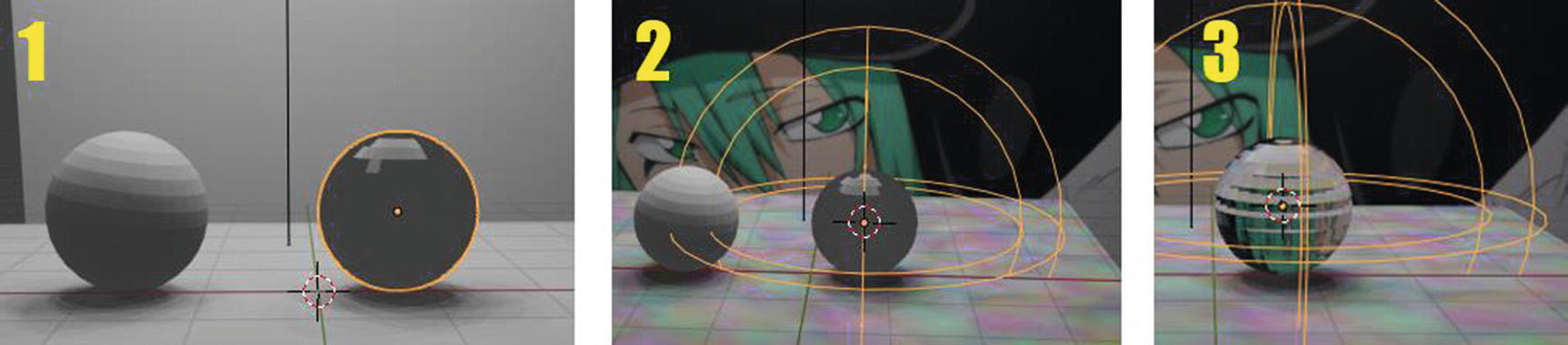
Reflection Cubemap at work
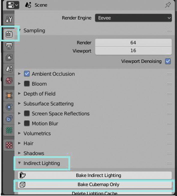
Render Panel ➤ Indirect Lighting ➤ Bake Cubemap Only

Reflection Plane at work
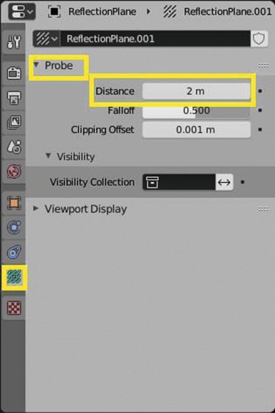
Object Data Panel ➤ Probe ➤ Distance
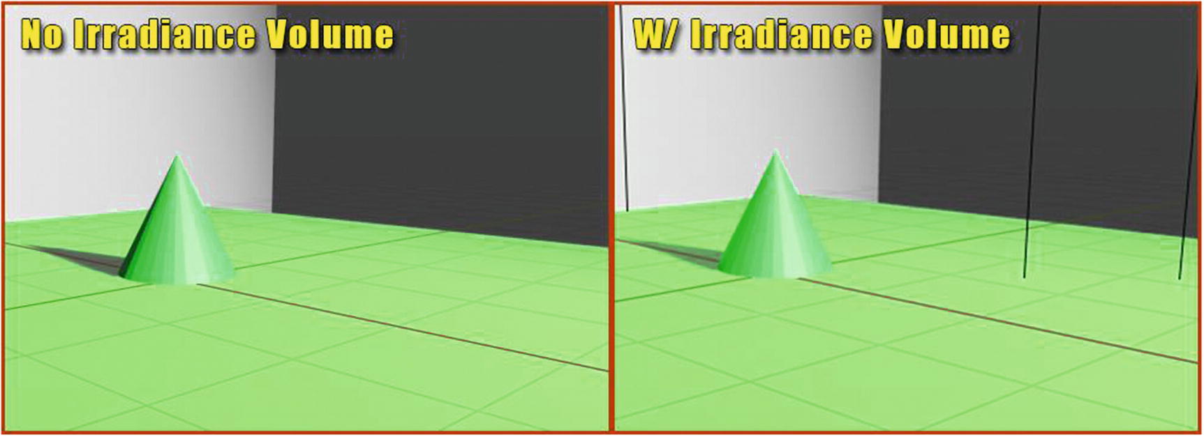
Irradiance Volume at work
In this example, I used a spotlight to be the source light with 50,000 watts. You can see in Figure 2-41 that irradiance volume gives a softer look at your scene compared to the one without irradiance volume. You can notice the changes, especially in the shadow, and how brighter the scene becomes. It calculates all of the light paths and the reason it looks softer and brighter is that it takes bounce lighting into account, which Eevee doesn’t naturally do.
I’d like to note that this is for Eevee engine only!
Now, let’s proceed to our next objects, which are the camera and speaker.
Camera and Speaker Objects
Camera is for capturing the scene you created for rendering purposes. For modeling, you can take it also as an object to help you see if your objects are in their right place. For animation, of course it has a vital role. You cannot create an animation (just like a film or movie) without a camera.
Speaker is for audio, obviously. It provides sounds in the 3D viewport.
Both the camera and speaker only have an object mode. Camera, by default, has already been set once you open your Blender or a new Blend file.
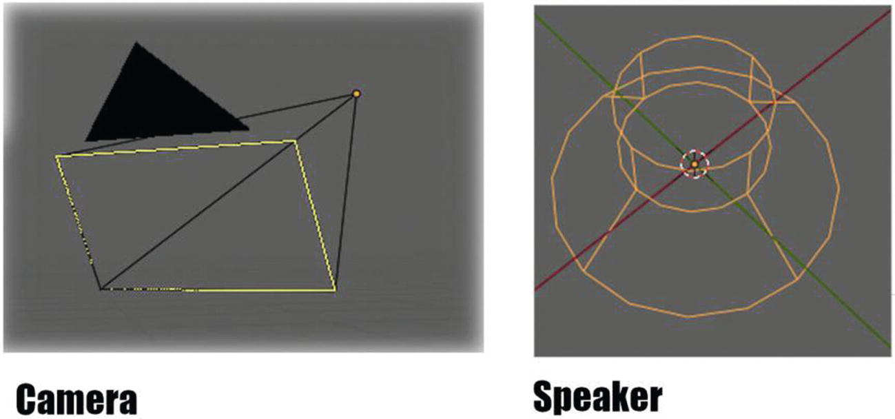
Camera and Speaker
What’s left now are the objects related to Force Field Objects, which are Force, Wind, Vortex, Magnetic, Harmonic, Charge, Lennard-Jones, Texture, Curve Guide, Boid, Turbulence, Drag, and Smoke Flow, but I decided not to discuss much of it since they are more for animations and simulations, and it takes more pages to discuss these objects effectively.
Now, we’re already done in our introduction and we’ll proceed to our main dish, which is about the modeling tools, which can be found in modeling workspace; and features of Blender that can help you create a game asset or game environment. I’ll be discussing this along with a sample project so it will be more fun for everyone. After all, examples are great ways of teaching.
Modeling Specific Tools
Blenders have tools that you can use even you’re doing things like sculpting, texturing, UV mapping, or just simply layout. There are also tools that are specific in those things. In this part, we’ll be focusing more on the specific modeling tools for modeling.

Toolbar for Modeling workspace (General: Red; Modeling Specific: Yellow)
The toolbar for modeling workspace has six general tools (I just called it general tools) and twelve modeling specific tools, based on icons present. Yes, there are more tools in it. As you can see in Figure 2-43, there are small triangles beside the icons of some tools. This means there are other tools hidden in it. So, let’s now start discussing these modeling tools.
Extrude Region

Extrude Region at work
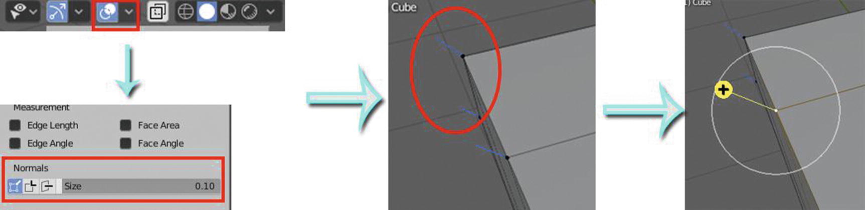
Enabling Normals
Let’s now discuss the tool that you can see together with extrude region. When you click the triangle, you will see a drop-down menu with a list of four tools including the extrude region. The other three are extrude along normals, extrude individual, and extrude to cursor. Let’s start with extrude along normals.
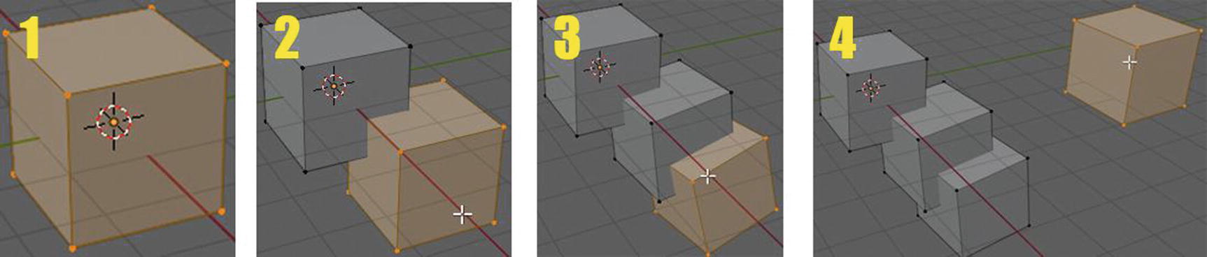
Extrude Along Normals
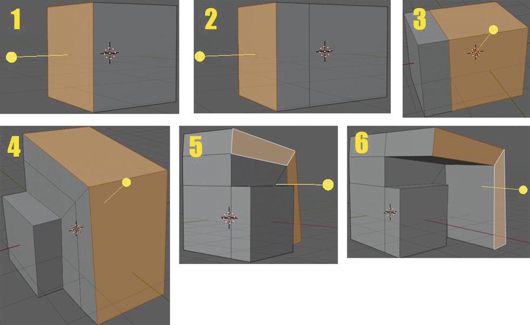
Extrude Along Normals tool at work
You can see in images 3, 4, 5, and 6 that after I select the two faces, they extrude together. You can also notice that the arrow in image 4 looks like it is in the center. This is because in extrude along normals, its computation for extruding is based on the selected elements’ local normals. You will understand this more after discussing the next tool, which is the extrude individual where the output is opposite to this tool. This tool has a shortcut key of Shift + Spacebar + 9.
Note that if you press Shift+ Spacebar + 9 all in a quick succession, it will actually enable the tool push and pull, but if you press Shift + Spacebar and then pause for the menu and press 9, it will take you to extrude along normals.
Extrude Individual
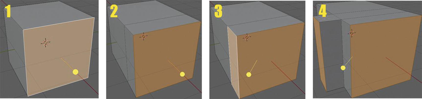
Extrude Individual tool at work
As you can see, at first, if you only select one face, it looks similar with extrude along normals; but if you select more than one, that’s the time you can see its difference. This is because, as its name suggested, it extrudes individually.
Extrude to Cursor
Extrude Individual tool at work
You notice that the duplicate or extruded part is located at the place where your cursor is. Okay. I guess this can be used if you want to create a small object with some base mesh, but you don’t want to use the particle system and you just want to randomly spread it in the scene. That’s what I’m actually thinking when I want to give an example on how this tool works. You can use it, too, for getting rough forms for modeling and sculpting, like for body shapes or hair. You can select a group of faces and then just click away, and it can help get organic shapes using some scaling and grabbing or rotovating. Also, this tool is one of the few tools that doesn’t have settings.
Inset Faces
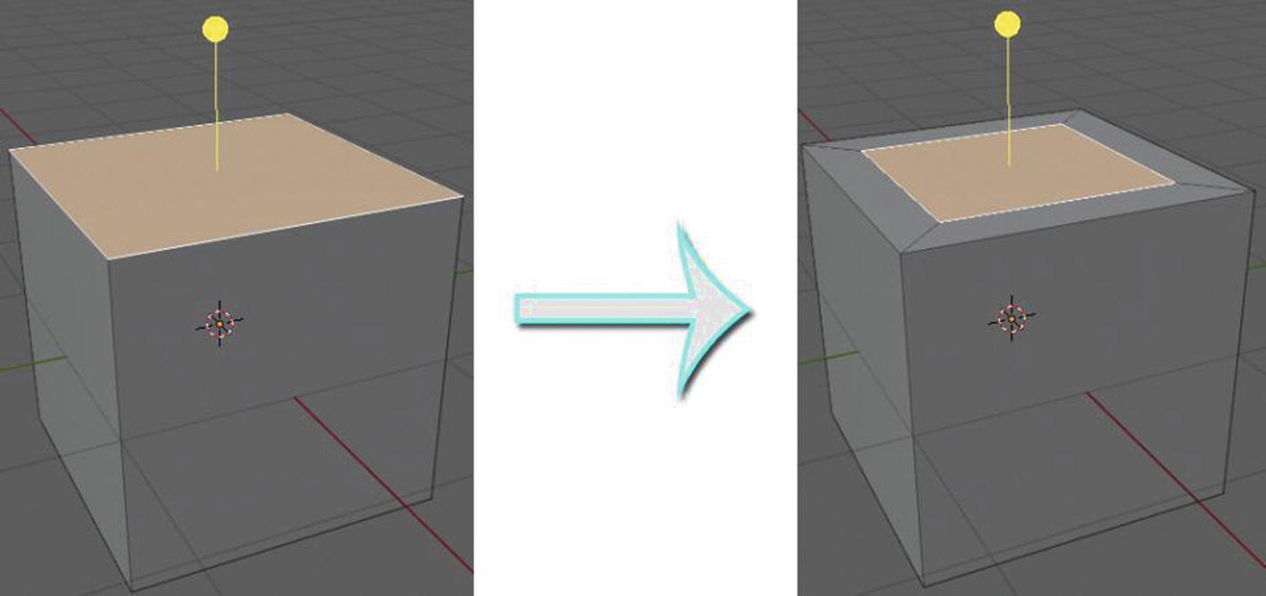
Inset Face tool at work
In order to achieve this kind of output, after you select the place you want to have your new face inserted, you need to first click the yellow arrow, or press I in the keyboard, and drag it to the center.
Bevel
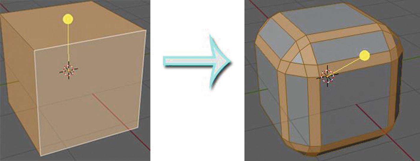
Bevel tool at work
This tool helps smooth the edges of your object, which is necessary for a realistic look since we all know is that there is no perfect cube or rectangle in real life.
Loop Cut
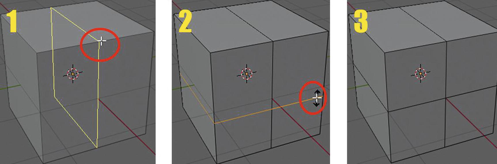
Loop cut tool at work
Once you choose the loop cut tool , whenever you position your cursor in the mesh, the loop will already position itself where your cursor is, just like in image 1. Just like in image 2, when you want to slide the loop before you make the cut, you need to drag it by holding the left mouse button. Note that when you drag the loop, it will only be dragged between the two cuts where it was located so before you slide the loop, make sure you already positioned it in the place where you wanted it to be placed. Also, as you can see in image 2, when you slide the loop, you will see a black arrow with two heads facing both sides. This indicates that the loop is being dragged, and also this arrow shows which direction the loop can slide on.
Just like extrude, there is another tool that can be seen together with loop cut. It is the offset edge loop cut.
Offset Edge Loop Cut
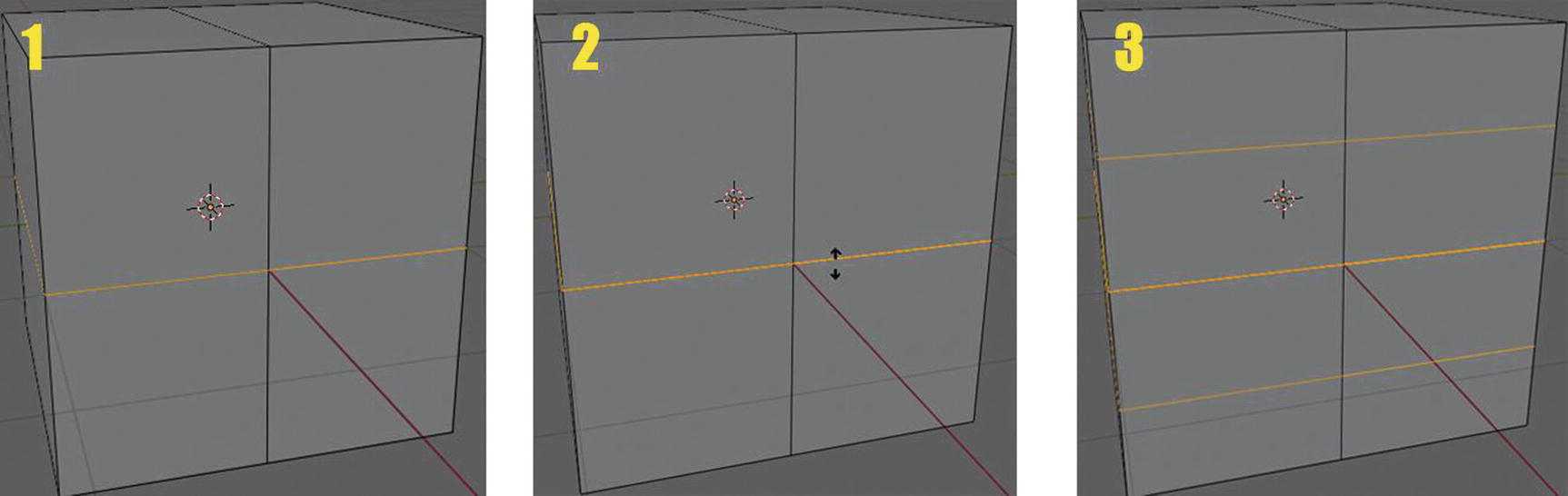
Offset Edge Loop cut tool at work
Based on Figure 2-52, we can say that these tools make the loop cutting easier. Since as I mentioned earlier, in loop cut, when you already choose to slide a loop, it will only slide in between two cuts. So, if you want to have a cut in the opposite side, you need to make another loop. As you can see here, in images 2 and 3, when we already drag the loop from the center, it creates two loop, where one is one going to the top side and one to the bottom side. And because these two loops are dragged together, at the same time, they are the same sizes.
Knife Tool

Knife tool at work
When you activate the knife tool, your cursor will turn into a knife, just like in image 1. When you start slicing your mesh, unless you press enter, just like you can see in image 2, the slicing will not stop.
Bisect Tool
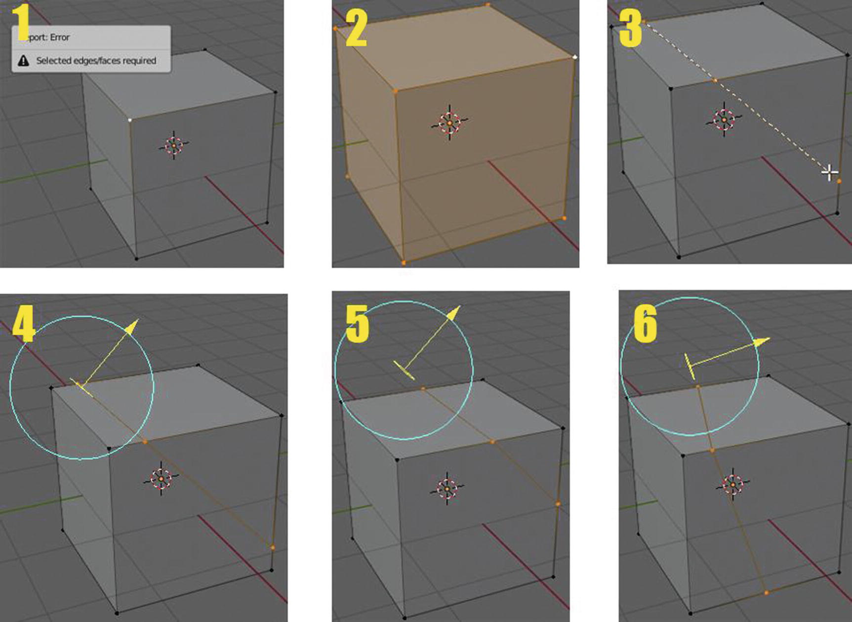
Bisect tool at work
Image 1 in Figure 2-54 shows the error you will encounter when you just select one vertex and use the bisect tool. When you use this tool, first you will select the part where you want to bisect and then select the portion or part by holding and dragging your cursor just like you can see in image 3. You can notice from images 4–6 that there is this yellow arrow and a blue circle around it. The yellow arrow helps you slide the loops or edges created by the bisect tool, and the circle helps you change the position by rotating it.
Poly Build Tool
Poly build tool at work
The blue color in the edge that you can see in Figure 2-55 indicates that you can already drag it and create a new face. I’d like to note that this tool is more for retopology.
Spin Tool

Spin tool at work
The blue curve with the plus sign at the endpoint of it is used to spin your selected elements. What you can see in image 2, the gray circle that surrounds the sphere, indicates the spinning you are currently doing. After you’ve done the extruding and spinning, two arrows will show: a green one; and a red one, which you can use to move the extruded part created by the spin tool. The red arrow is for the X-axis and the green arrow, of course, is for the Y-axis.
Spin Duplicates
Spin duplicates is the same as with Spin tool. It also have a blue curve that you use for spinning and a gray circle that when you do the spinning, shows the green and red arrows after you’ve done extruding and spinning, and it also has the same output. So, what makes it different? It duplicates the data of the main objects or elements. There is no figure for this one since the output will be the same as the spin tool.
Smooth Tool and Randomize Tool
The smooth tool flattens angles of the selected vertices. You can see a yellow arrow to selected elements when you use it. You can say this is more useful when you already have many vertices and you want to make your object smoother.
The randomize tool, as its name suggests, randomly arranges selected vertices. Just like the smooth tool, it also has the yellow arrow to a selected element when you use it.
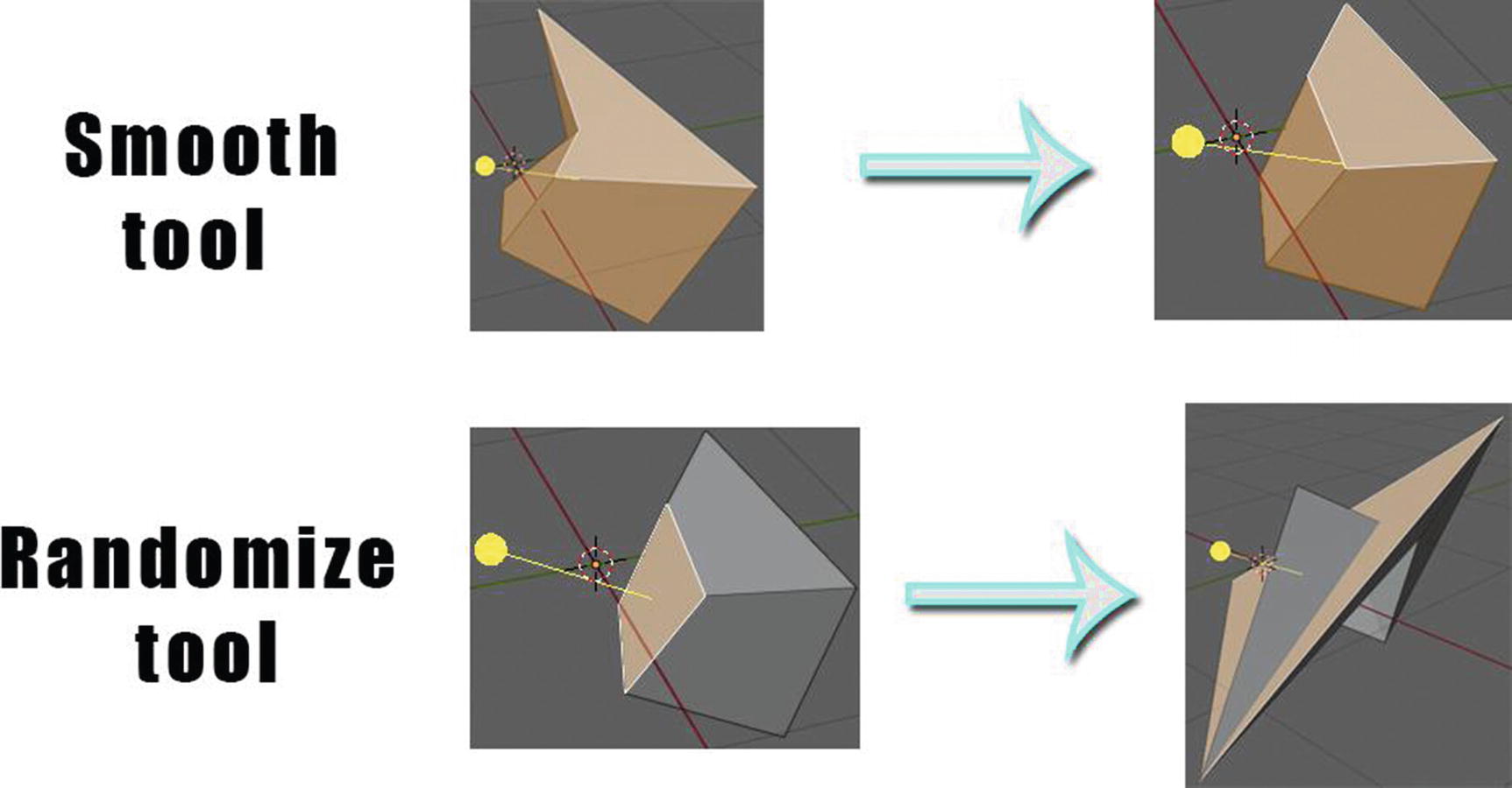
Smooth and Randomize tools at work
You can see in Figure 2-57 how the smooth tool changes the mesh object from having rough edges to a mesh object with smooth edges. With the randomize tool, you can see how it randomly scaled out the face selected.
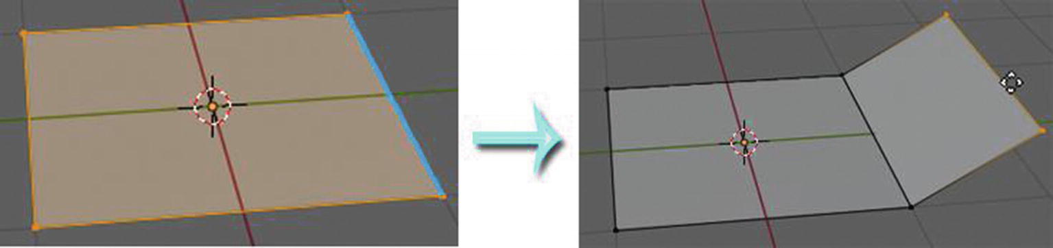
Edge Slide Tool and Vertex Slide Tool
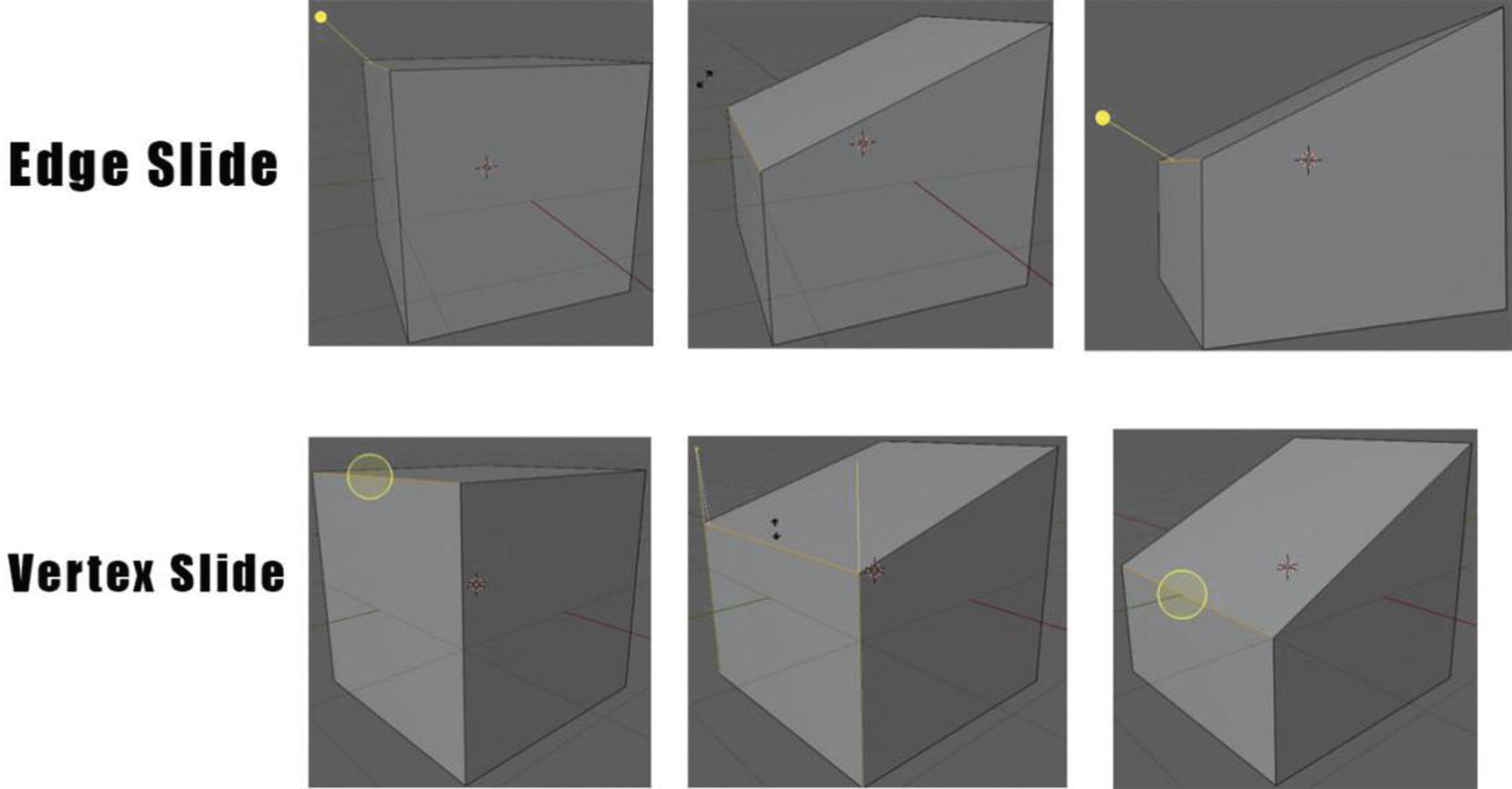
Edge Slide and Vertex Slide tools at work
As you can see in Figure 2-58, they have the same output and same function, but as you can clearly see, even though I selected an edge to slide for the vertex slide tool, it shows how it affects the vertex by showing the previous position of the vertices that have been dragged.
Shrink/Flatten Tool
This tool simply shrinks or flattens the elements along the direction of the normal. It is like the transform tool, which is part of the general tool, since when you select just a face and apply it, it looks like you’re just moving the face; but when you select the whole mesh, it appears like you are scaling the whole mesh. The transform tool can scale, move, and rotate an object. In my opinion, the difference between the transform tool and the shrink/flatten tool, aside from shrinking/flattening can’t rotate any elements; it is specific to modeling unlike the other one. However, the transform tool can be used in other workspaces. Another difference between the shrink/flatten tool and transform tool is its settings. It has a proportional falloff option and offset.
Push/Pull Tool
If the shrink/flatten tool is like the move tool, the push/pull tool is like the scale tool. It pushes or pulls the selected elements. It also has the same settings as the shrink/flatten tool.

Shrink/Flatten and Push/Pull tool at work
As you can see in Figure 2-59, both the shrink/flatten and push/pull tools have a yellow arrow with a round head. This arrow indicates where your Normal is pointing. The settings will not appear unless you already dragged the selected item. Just like in our example, you cannot see the settings when I click the face. But after the application, when I have flattened the cube for shrink/flatten and scaled in for push/pull, its settings appear. That’s only the time you can play with the proportional falloff – if you enable proportional editing and other settings they have.
Shear Tool
Now we have a shear tool . This tool shears selected items along the horizontal axis of the screen.
When you select the shear tool, there are arrows pointing to different axes appearing on the selected elements to modify. When you click and drag the head of this arrow, which looks like the letter X, the selected element is sheared to the axis, toward the Y-axis, or even in the Z-axis; it depends on which direction the X arrow head is pointing to. You can also change the direction by changing the offset value and axis in its settings

Shear tool at work
As you can see in Figure 2-60, we have three arrows connected to each other, and the arrow head looks like the letter X. Each arrow head represents two axes. The arrow with the yellow-orange head represents the X-Y-axis; the arrow with the pink-violet arrow head represents the X-Z-axis; and the arrow with the green-blue arrow head represents the Y-Z-axis.
To Sphere Tool
Let’s talk about the to sphere. This tool moves the selected vertices outward in a spherical shape around the mesh center.
To Sphere tool at work
As you can see in Figure 2-61, after I dragged out the selected vertices, it formed a spherical shape. You cannot appreciate its function if you only selected three vertices in line with each other, or two faces in line with each other. Since it forms a spherical shape, it is best when you select vertices, edges, or faces that you will make in a form of a circle.
Rip Region Tool and Rip Edge Tool
The rip region is only applicable with vertices while the rip edge tool is applicable to both vertices and edges. When you use rip edge in faces, you cannot see its effect. It only moves the face. Rip regions rip polygons while the rip edge rips the vertices. Also, rip region extends the vertices and automatically connects them to other vertices while rip edge extends the edge and cuts or rips it out from the mesh.

Rip Region and Rip Edge tools at work
Now, we’re going to proceed to the last part of this chapter: a sample project with a discussion. For this one, we’ll go for creating a game asset for a game environment rather than a whole game environment so we can at least discuss more with fewer pages. After all, you cannot create a game environment without the game asset.
So, now, let’s start the fun!
Sample Project - Pawn Chess Piece
Yes, we’ll be doing a chess piece here as a sample project. The first step, of course, is that we need a reference. I’d like to note here that in making a game environment, or even just a game asset, it is still important that you have a story or a theme for it. If you don’t have, trust me – you will get lost. What I mean is, if you are like me who can easily be filled with ideas, then you will be confused as to what you will do and end up doing nothing. So, it is better that you have your theme or story as a basis for the game assets you will be creating. Don’t worry. You don’t need to become a novel writer to come up with a story. You just need your imagination. Imagine what makes you happy or excited. If that doesn’t work, take a look at what kind of movies/dramas/comic books/stories you are fond of. You can get ideas from them. Just take a look around you.
For this step, Figures 2-63 to 2-75 will be about modeling the pawn piece. So, first, we need a reference image. I searched my reference image in Google, though there are other sites where you can search too, like Pinterest, Flickr, 500px, etc. I check for both the front view and the top view for this model.
Let’s now start the modeling.
First, I’ll import my reference image in Blender by pressing Shift + A then going to Image ➤ Reference. You can also just drag and drop images into the 3D viewport, in the background, if you are in object mode. You can also do this by going to Add menu ➤ Image ➤ Reference. I’d like to note that for you to effectively use this reference image object, you must already be in the axis or view where you wanted to use your reference image. For example, I want to use my reference image in the right view side, so I will set my 3D viewport view to the right view by pressing numpad 3 or going to View menu ➤ Viewpoint ➤ Right.
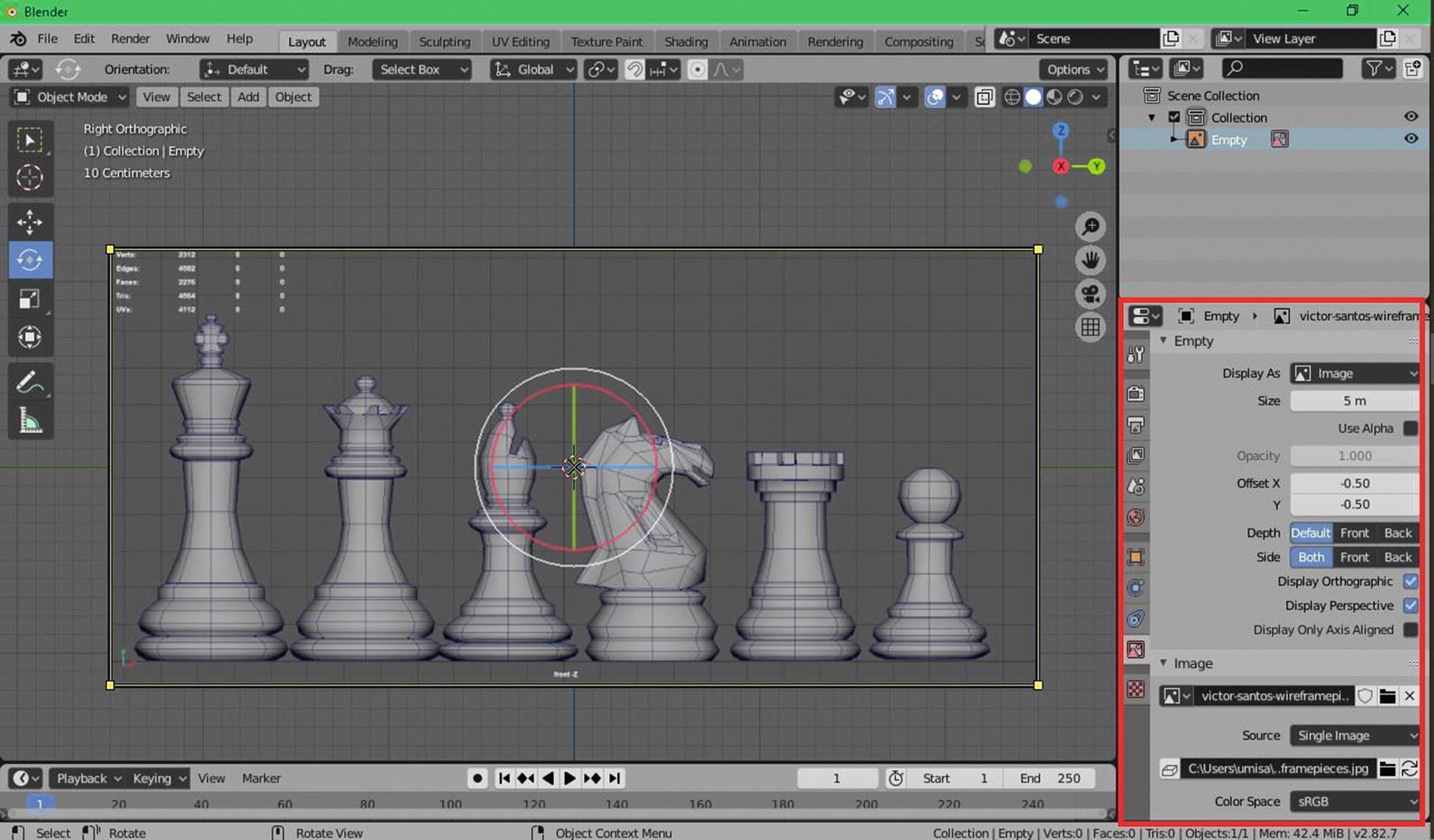
Image Reference Object. Reference Image credit to Victor Santos: (www.artstation.com/artwork/qAJV92)
The one in the red rectangle is the properties panel. Since what we currently have is the image reference object, what you can see in the object data are the settings or details pertaining to the reference image object.

Settings for changing vertices
By lowering the value of vertices, for example, take 32, divide by 2, and this will be 16, so you can have a lower number vertices that can help you with your work.
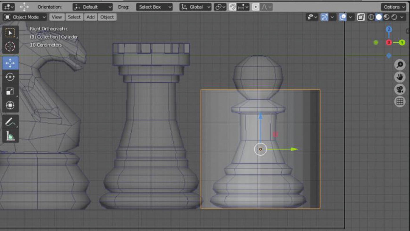
Placing cylinder next to the Reference Image
Now, we’ll start modeling our pawn by adding a cylinder. Again, I add a cylinder by holding Shift + A ➤ Mesh ➤ Cylinder. You can also do this by going to Add menu ➤ Mesh ➤ Cylinder. At this moment, I’m still using the layout workspace so I can create the pawn object as a separate object. You can also do this in the modeling workspace by just changing the mode type into an object mode.
I just set the opacity of the image reference to 0.392 so I can trace my model to the image effectively. I’d like to note that for you to avoid having a hard time later, make sure that you will not deform your base mesh. Just like in this pawn, if I ever deform the cylinder because I’m scaling it up to fit in the reference image, which usually happens to beginners, it will become harder later for to create a smooth look for the pawn piece. Just remember, we don’t need to be too detailed at first. We just need to see the shape that resembles our reference image. For our pawn, we have a cylinder. We just need to place the cylinder next to the reference image just like what you can see in Figure 2-65.
I didn’t scale it up since I will also do it later on as we model it to be like the pawn. But for now, let’s start the first phase of modeling.

Red Rectangle: selection settings for vertices, edges, and faces
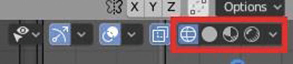
Red Rectangle: Shading settings
From the left side will be the Wireframe, Solid, Material Preview, and Rendered.

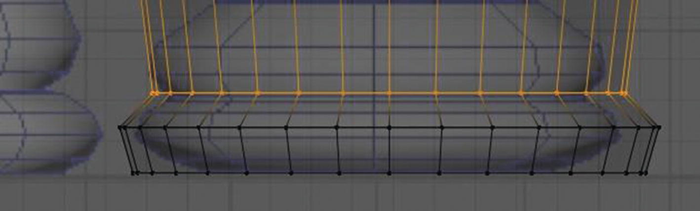
Scaling the selected vertices at the bottom
Adding new loop
At this point, the only thing I’ll do is to add a loop and move the loop by pressing G. But of course, I make that sure before I move the loop, all vertices are selected.

Current progress of the Pawn
Now, as you can see in Figure 2-70, we already covered the body of the pawn, but the head is still not yet done and we already used the base mesh. This is the time now where extruding will be handy. First, I’ll scale the last loop to fit to the lower part of the head of the pawn and then start extruding by pressing E on the keyboard. You can also use the extrude region tool for this.
What I’m going to do here for the head is just extruding and scaling.
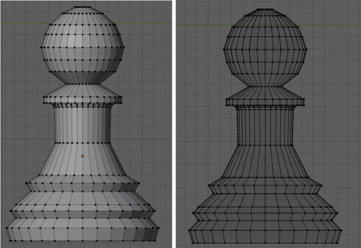
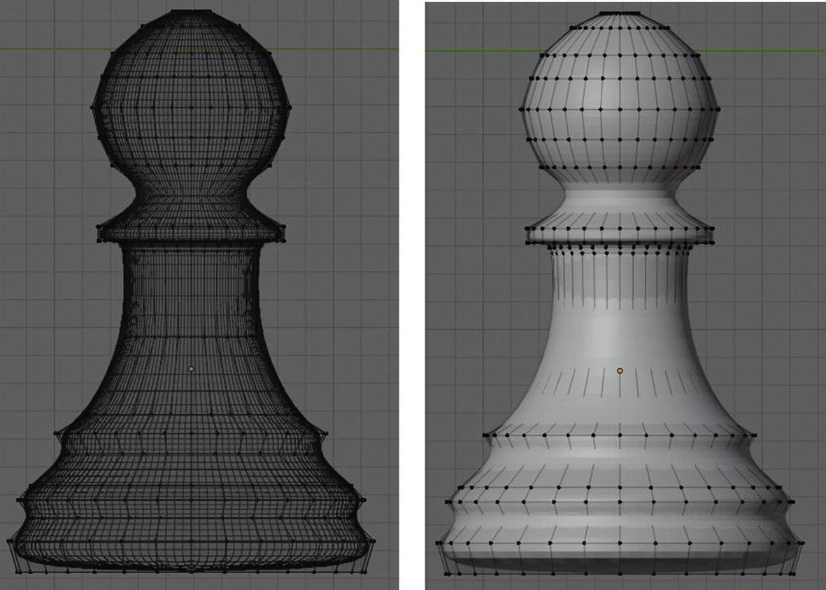
Current progress of the Pawn (Left: Solid mode, Right: Wireframe)
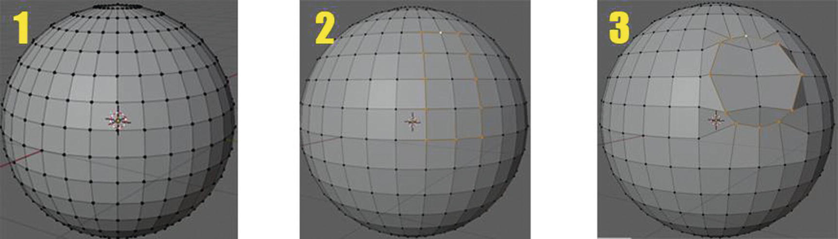
As you can see in Figure 2-71, it already takes shape: from just a simple cylinder to a pawn chess piece. Now, let’s smooth it by using a modifier called subdivision surface.
Subdivision surface is a modifier used to split faces of mesh into smaller ones, making a smooth look on mesh. It helps you to lessen the usage of too many vertices just to smooth out your mesh.
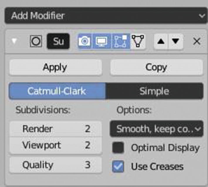
Subdivision surface Modifier Settings
The other options with a select menu in the settings of the subdivision surface is for handling the UVs during the subdivision. It has two options that are smooth, keep corners wherein the UV islands are smoothed but the boundaries are sharp and the sharp wherein the UVs are unchanged.
Subdivision surface Modifier applied
See how smooth our pawn was. Now, let’s adjust our vertices to fit into our interests: just a basic commands now like G for move and/or S for scale. Note that you need to switch back to solid mode in order to see the image on the right.
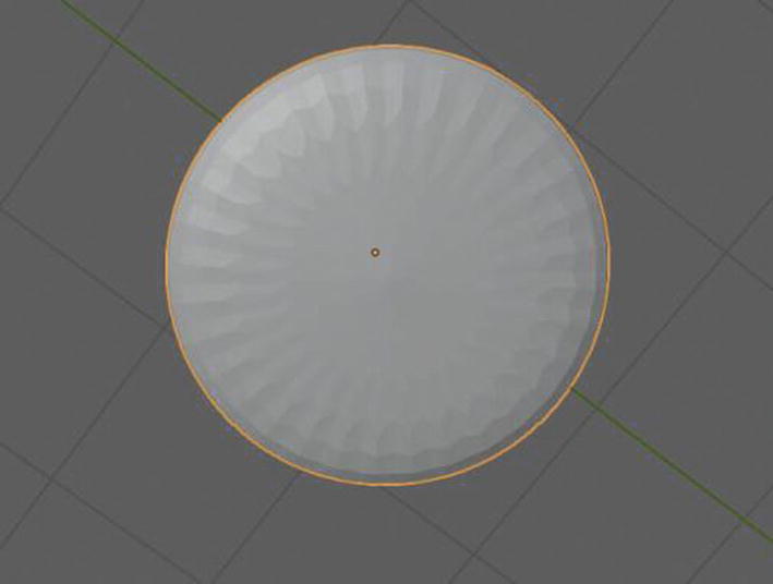
Bottom of the Pawn
The reason for this is because we are using geometry. Remember that base mesh is a cylinder, and then we add a subsurface modifier. You can say that the face at the bottom of the cylinder mesh becomes too crowded because of too many vertices that it already can’t handle. So, in order to fix this, first, we need to select the vertices or faces involved, and then we’re going to use the inset tool by pressing I, then dragging it inward. By doing this, it seems that you are adding another loop and it smooths that part of your mesh. Last, after I have done the editing, I make it smoother by going to Object Menu ➤ Shade Smooth.
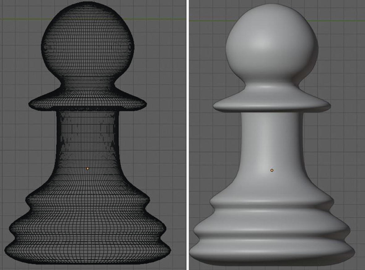
Final modeling for Pawn Chess Piece (Left: Wireframe, Right: Solid)
Sample Project - Rook Chess Piece
I’ll start now with the next chess piece, which is the rook. With the same process, I’ll add a cylinder and place it next to the reference image. Then I’ll make a first phase of modeling by scaling and moving the vertices in the wireframe view.
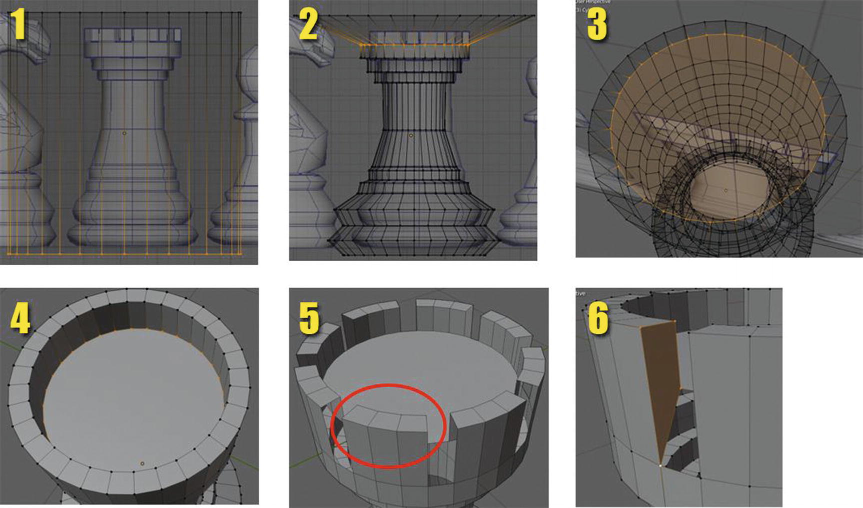
First Phase of Rook piece
In image 1, you can see how I place the cylinder next to the reference image. In image 2, you can see how I scale and move the vertices so I can fit it to the image reference. In image 3, you can see how I use the inset tool to create a loop cut at the top of the cylinder base mesh to create the top part of the rook piece. For me to achieve the result in image 4, what I did is while the loop cut, I recently made using the inset tool was selected, you can press G for move then Y for Y axis to restrain the movement to Y axis. If you want to scale only in Y-axis, press S for scale then Y key. If you want to rotate in Y axis only, press R for rotate then Y key. If you want to restrict the movement in Z-axis, you can press G for move, then Z for Z-axis. To limit the scaling in Z axis, just press S for scaling key then Z key. And to limit the rotation to Z-axis, press R for rotation then Z key.
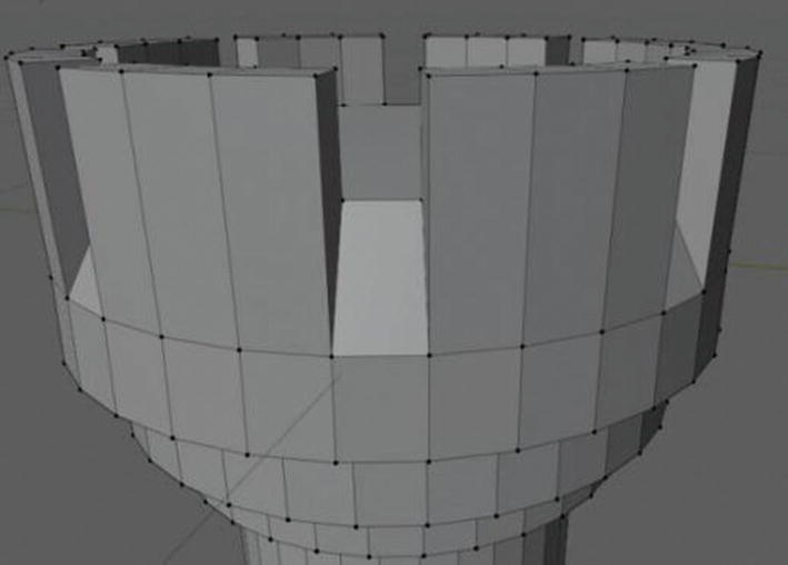
Let’s now proceed to image 5 of Figure 2-76. For reference, let’s call the one inside the red oblong, in Figure 2-76 image 5, a column. In order for me to achieve the output that you can see in image 5, I divided the 32 columns by 8. So, we have 4 columns in each group. Then I delete one column in each group. In this way, I get an even number of columns in each group. Since we delete this, we called it a column, which is composed of vertices and faces, and we create a hole in our mesh. Just like you can see in image 6, in order to fix this, I select four vertices, first is the four vertices at the side of the one column and press “F” as a shortcut in creating faces. Then I select the other four vertices in the side of another column and press F again to create faces. Then select the remaining four vertices that are in the middle of the two columns.
First Phase: Top of Rook piece

Current progress of Rook piece
Second Phase of Modeling of Rook piece
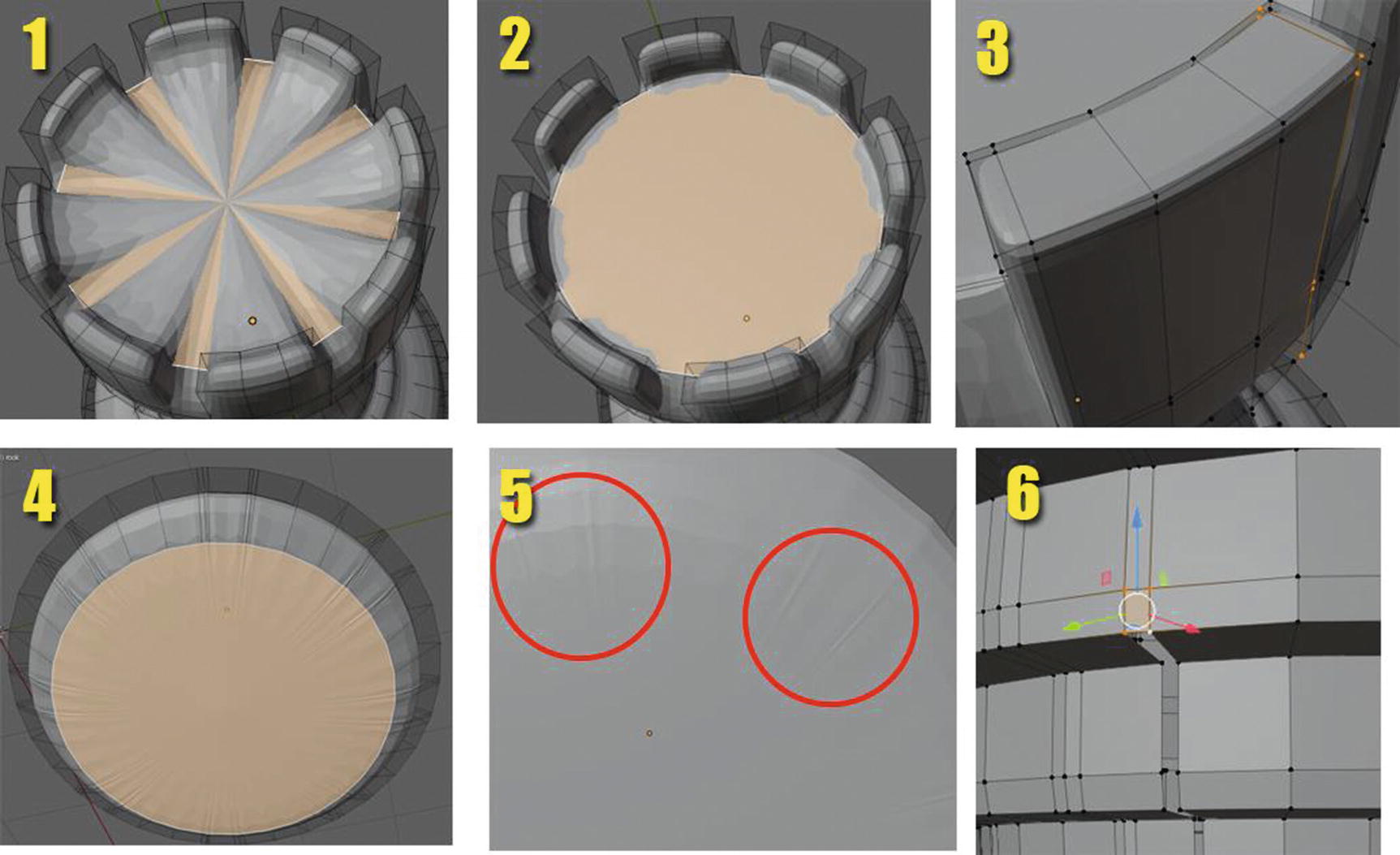
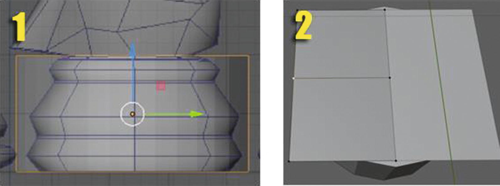
For the second phase, aside from fixing some stuff after I applied the subsurface modifier, I use the inset tool at the top of the rook as you can see in images 1 and 2 of Figure 2-79. I add new loops to create the look I want for the column like you can see in image 3. I also use the inset tool at the bottom of the rook as shown in image 4. This is the same method that we used in the pawn piece.
Okay. Let’s discuss a little bit what can make your edges sharp. First is when you add a crease. When you add a crease, yes, you might have sharp edges, but you don’t have full control over it. Adding loop cuts and dragging them near to the other loop cuts can also sharpen your edges but also increase vertices.
Now, as you can see in image 5, I encircle part of the bottom of the rook that has unwanted artifacts. These are the effects of the loops I added. It’s because the vertices and edges at the bottom of the rook become too close to each other. In order to fix these, you just need to delete some vertices and edges that create only small faces and then replace them with some larger faces as can be seen in image 6.
But I want to note that this is up to you if you want to still fix these small problems – because , for example, your game asset will be placed in the background. Do you think making it too detailed will help? If that bottom part of the rook will not be seen in the game you are creating, will it be necessary for you to take time to fix it that much? This is where what we learn regarding low poly vs. high poly will be useful.
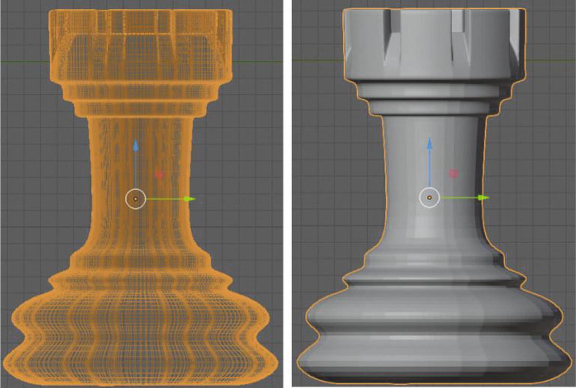
Rook Piece (Left: Wireframe view, Right: Solid view)
Sample Project - Knight Chess Piece
Let’s proceed with the knight piece. We will have a different approach here because it isn’t as simple as the first two pieces, but I will only show in figures those highlighted parts of the process. We will now begin.
Knight Piece process
First step, I created the base using the cylinder. For the base, it was the same method with the base of the pawn and the rook. Then it was scaling and extruding, as well as transforming and using the inset tool in the bottom part.
In the top part, the horse head, take a look at Figure 2-81, where things become different. First, from the modeling workplace, I go to object mode and I add a mesh plane object by holding Shift + A ➤ Mesh ➤ Plane. Then, I go back to edit mode and hold Ctrl + R, then enter to create a loop in the plane. For this particular process, I make sure that the loop is in the center. Then, I select the face at the right side of the plane and delete it. Now, I add the mirror modifier, which copies what you do to certain elements. In this way, it will help me do this project easier since I will only worry about the left part. I don’t need to worry about the other side.
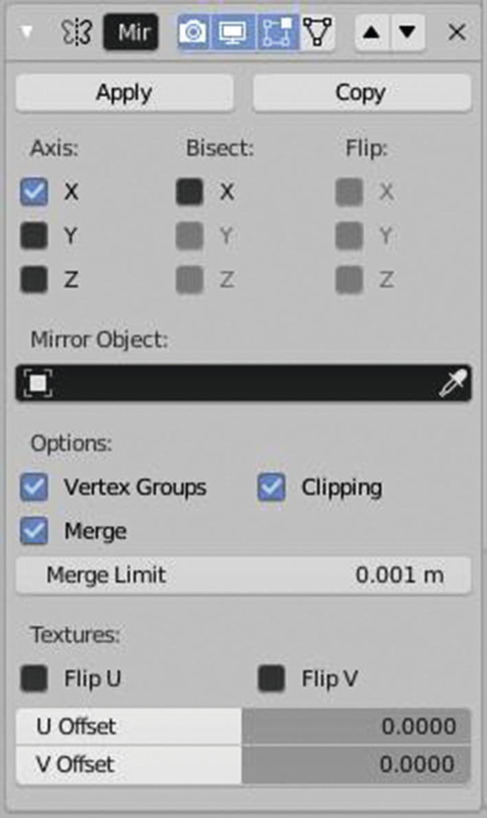
Mirror Modifier
The settings for axis indicate the axis that will be mirrored. The bisect settings enable you to cut the mesh across the mirror plane. The flip settings flip the direction of the slice. Mirror object is where you can choose a particular object to be mirrored. Clipping prevents the vertices by passing by the mirrored element during the transformation, and merge merges the vertices within the merge threshold. Vertex groups mirror the vertex groups and merge limits indicate the distance of the merge-mirrored vertices. The part under textures are all settings for applying textures in the mirrored vertices.
By default, clipping is unchecked, so I enable it to make sure that I will not go beyond the part of the mirrored elements.
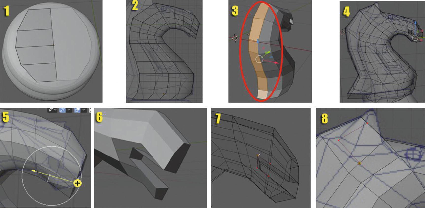
Highlighted process for Knight Piece
After adding the mirror modifier, I once again use Ctrl + R to create three loops in the plane and form it into a circle that will match the base that I made as you can see in image 1 of Figure 2-83. Then, I extrude and transform, using the move, scale, and rotate tools, the circle you can see in image 2 of Figure 2-83 to form the basic shape of the knight. After that, I select the face at the back of the head and extrude it to form the hair-like part for the knight as you can see in images 3 and 4 of Figure 2-83. Then I select the part of the head that is nearer to the mouth and extrude it toward the inside as you can see in image 5. And since after I extrude this part, it will leave a face outside, at the side part, which is not a lot like a mouth, I deleted the vertices left outside that leave spaces just like you can see in image 6 of Figure 2-83. In order it fill it in, I use the knife tool as you can see in image 7. Then, I add the ears using the knife tool as you can see in image 8 of Figure 2-83.
This process needs a lot of practice for you to be able to achieve your real goal so if at the first attempt you don’t make it, don’t be frustrated. Just try it again, match and closely look at your reference, and you will be able to achieve.
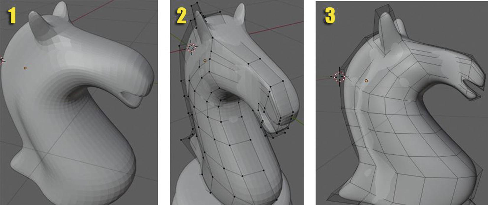
Knight Piece Second Phase
You might notice that I didn’t add eyes. Well, that’s part of the creativity aspect. We can add or delete some details as long as the basic or main concept is still there. In this part, we’re doing a knight piece. As long as the silhouette or the thing that can make the knight piece is still there, it doesn’t matter if we delete some small details like the eyes.
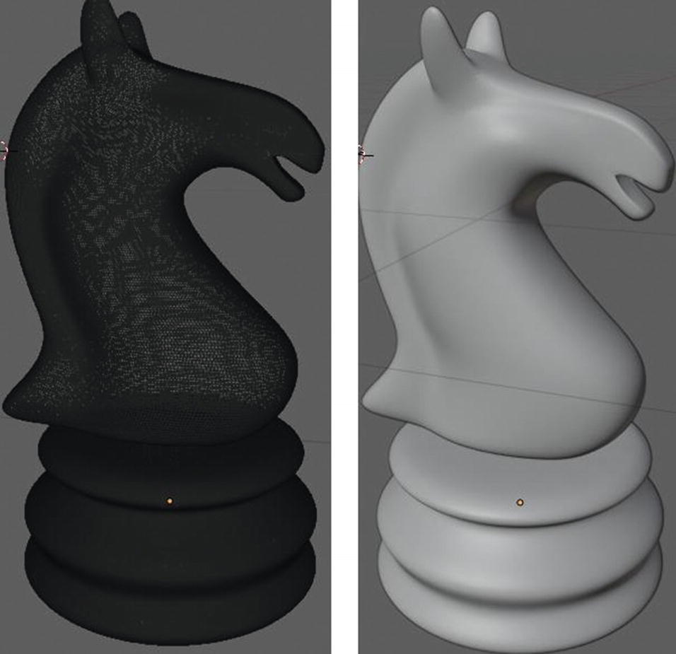
Knight Piece finale in Modeling (Left: Wireframe view, Right Solid view)
As you can see in Figure 2-85, in the wireframe view of the knight piece, it seems to have a lot of vertices already. It’s the effect of a subsurface modifier. Remember that if you don’t need to have that much detail, and your asset doesn’t need to be that smooth, just lower your values in the subsurface when you use it because it will also affect your rendering in the end.
Since we have only left the king, queen, and bishop, I will not discuss much of its process since it also has the same methods with the previous chess pieces.
Sample Project - Bishop, Queen, and King
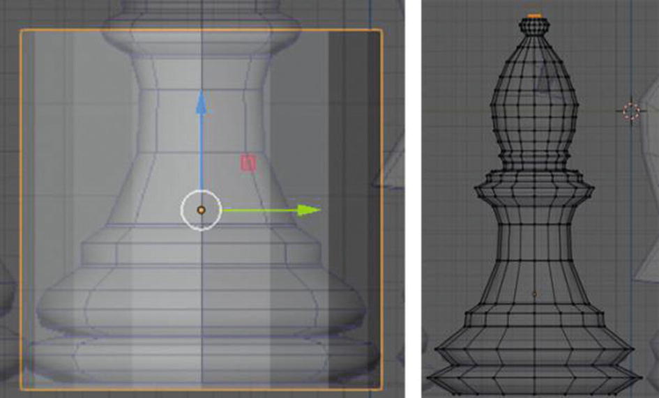
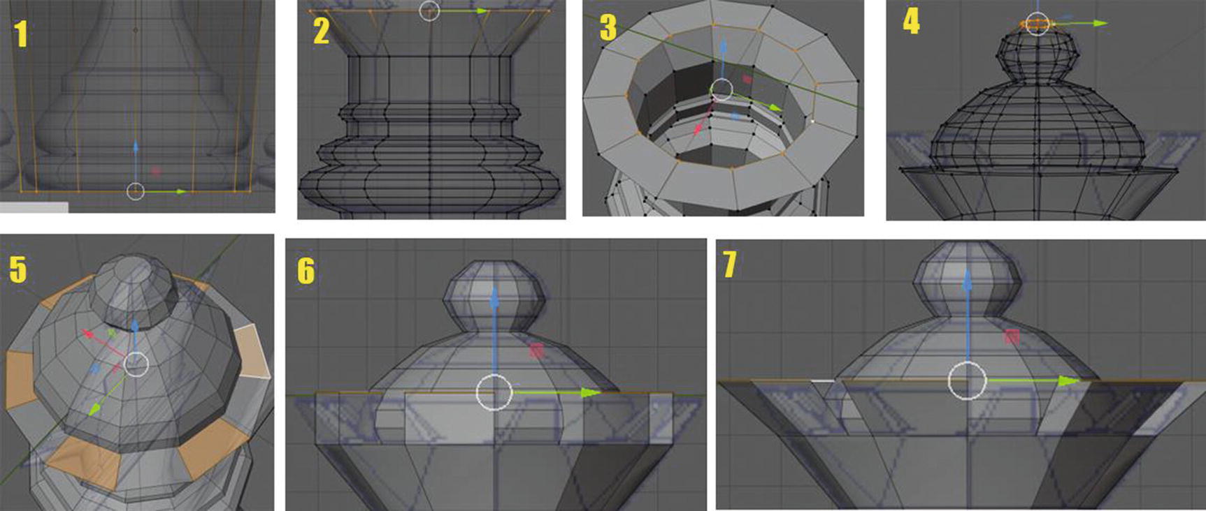
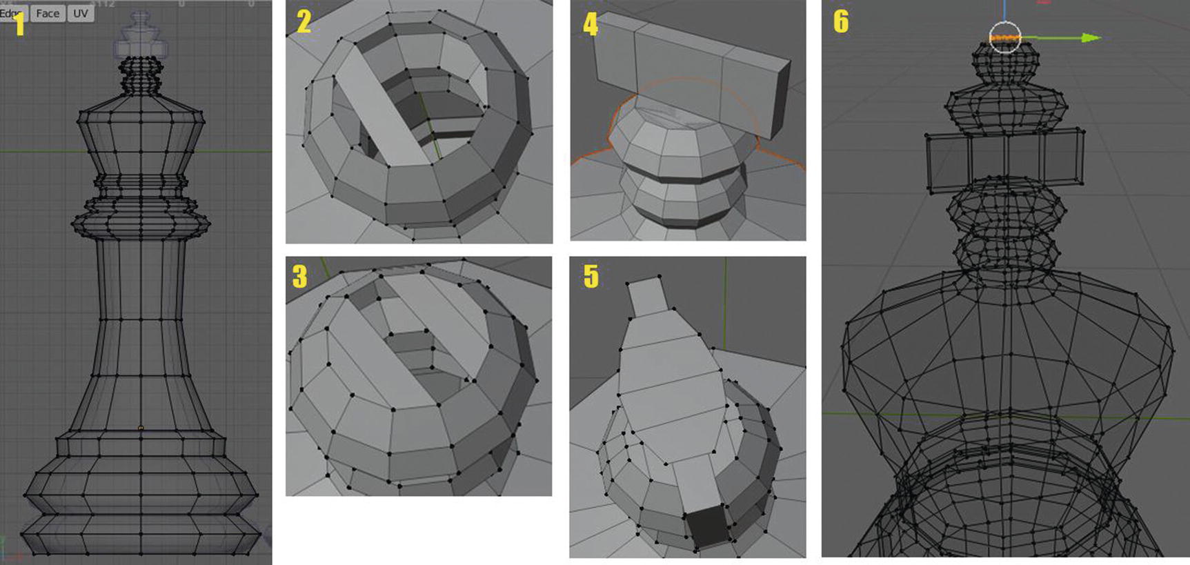
Bishop Piece process
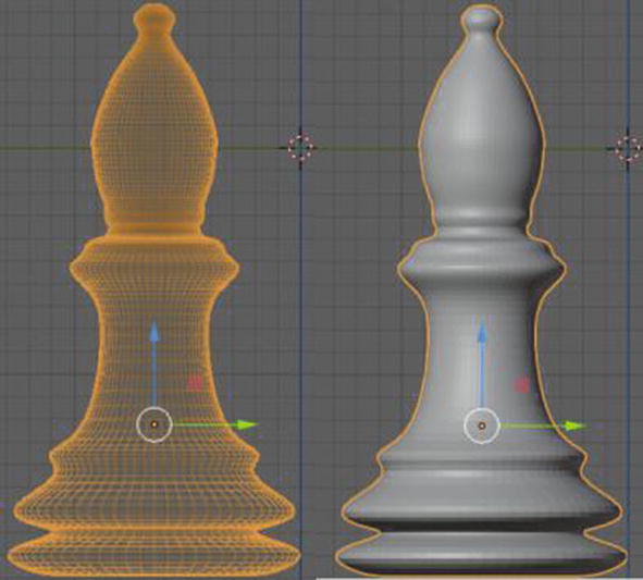
Bishop Piece finale in Modeling (Left: Wireframe view, Right: Solid view)
Queen Piece process
You can notice in Figure 2-88 that the technique I did with the queen piece is the same with the rook. Again, I use the cylinder, transform, extrude, and then when it comes to the crown, I just extrude the top loop just like you can see in image 3 of Figure 2-88, then extrude the faces as you can see in image 5. As long as you have the reference, and you know the basics like vertices, faces, edges, scaling, moving, rotating, and then extruding, you can easily do this modeling. Well, of course, constant practice is a must too.
I’d like to note that I set the segment of the cylinder to just 12 from its settings that show when you add the mesh. That setting cannot be changed when you already move or do an adjustment to your object.

Queen Piece finale in Modeling (Left: Wireframe view, Right: Solid view)
King Piece process
Again, I just use a cylinder and set its segments to 12. Just using the scale and extrude, I came up with image 1 of Figure 2-90. For me to create the top part of the king piece, I delete the top circle face and reconnect the vertices as you can see in images 2 and 3. I extrude the face at the center to create the cross as you can see in image 4, and then I use the knife tool to create a loop that can help me make the rounded part of the cross like the top of the king piece as you see in image 5. Then, once again, I just highlight the vertices to transform and use extrude and scale to complete what you see in image 6.
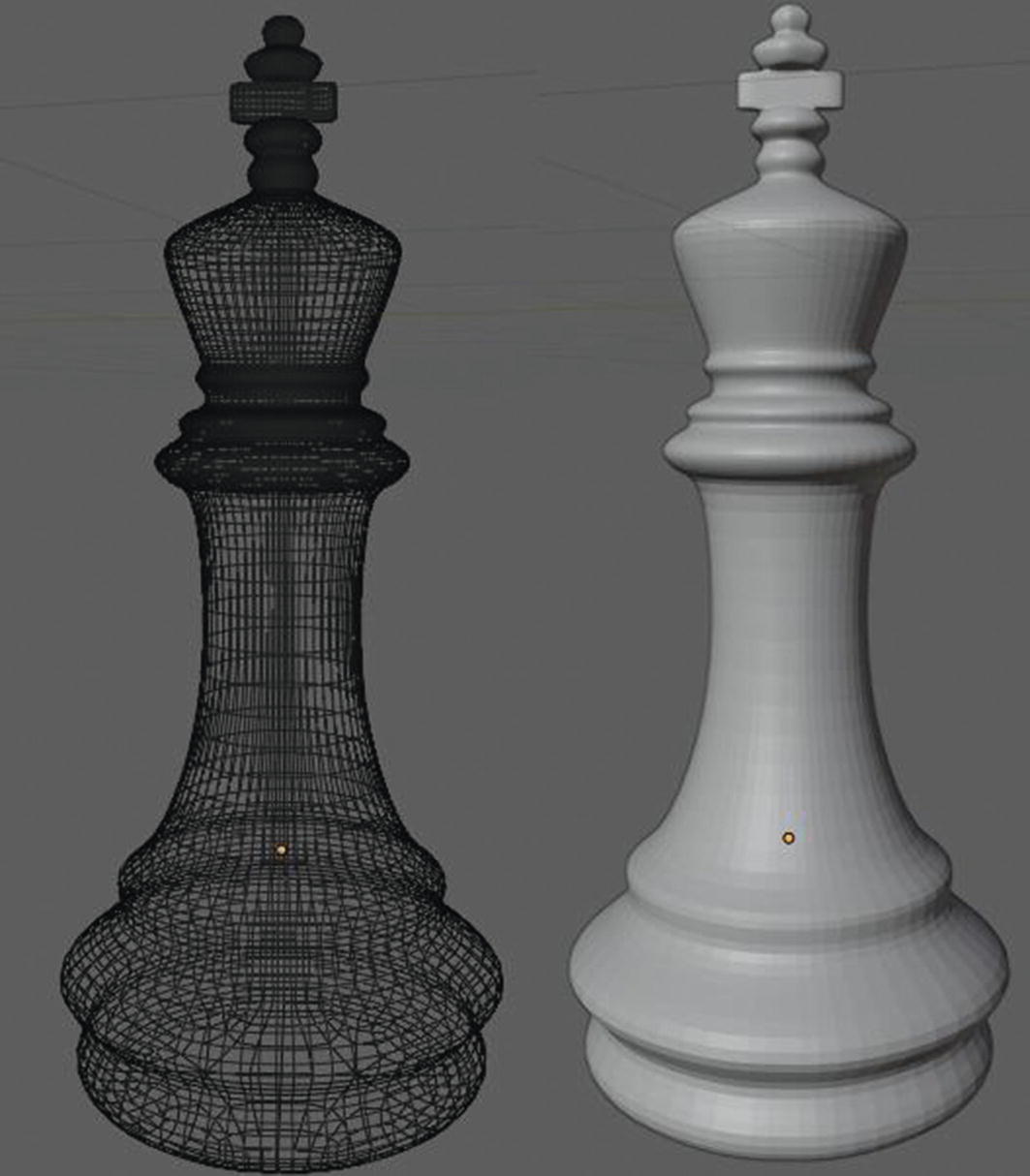
King Piece finale in Modeling (Left: Wireframe view, Right: Solid view)
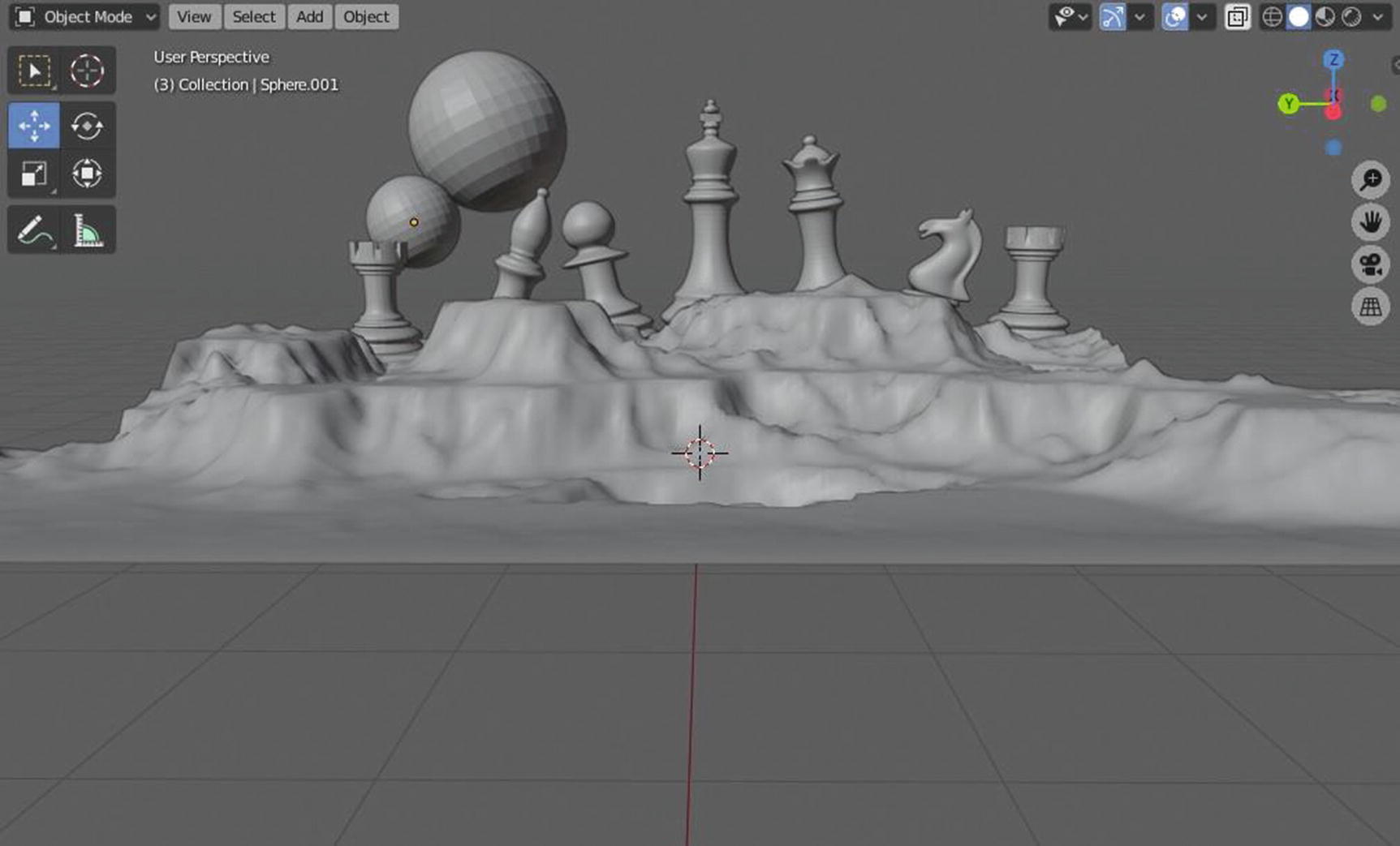
Sample Project Game Environment in Camera Perspective
So here, I use the add-on landscape that you can enable in preferences by going to Edit menu ➤ Preference ➤ Addons ➤ Add mesh: A.N.T. landscape. This add-on can be found in the sidebar menu of the 3D viewport, which you can also access by pressing “N” on your keyboard.
I just modified some stuff in its settings until I see my preferred setup and here it is. It was just a plain scene for a game environment design. I don’t want to create some complex one since what I wanted to tackle was the basics, which we always forgot.
As you can see, most of my chess pieces have high vertices. As you can see in Figure 2-92, although the chess pieces are in the background, I’m making them stand out by enlarging them. When it comes to texturing, the number of vertices will also affect them. And since I want these chess pieces to stand out in the background at least, I want them to have both good geometry and textures.
Now, we’ll now start Chapter 3! I hope you continue to enjoy this book.