10
Methods and Tools to Secure ICS
10.1. Identification of assets
A prerequisite for any risk analysis is to carry out an inventory of the installation. This involves identifying the elements of the control system and its interfaces with, on the one hand, the physical world and, on the other hand, the world of data processing. This inventory includes links to the business computing system, Internet access, remote connections by modem or via other types of connections and exchanges via removable memories such as USB sticks.
System components are hardware components, software components and communication equipment. Human elements can be added to it. It is also useful to identify the material and logical links between the machines. We get what is called a mapping of the facility.
If the cybersecurity study takes place as part of the design of a new facility, there are documents describing the functionality and planned implementation. There is also usually a functional safety study on which to base it. In the case of an existing installation, the description of the installation will be based on the actual installation and the various documents available.
First, it is necessary to define the scope of the study: it is chosen to contain all the critical part of the facility or infrastructure (networks, transport, electricity, etc.). If the installation is complex, it may be advisable to divide it into subsystems, if possible by grouping by criticality levels.
The description of the perimeter must be done in terms of functionalities, of geographical location and in terms of time (period of life of the installation in which we are interested). From this perimeter, it must be possible to assess the number of in/outgoing flows from each of a material, informational and human point of view. The next step is the understanding of the general functioning of the installation and the identification of business needs. To do this, we look for the main functions or processes provided by the installation. Then it is necessary to understand the links between the logical (data and software) digital devices and the physical part. The equipment at the interface is mainly programmable logic controllers and IIoT equipment.
| Functions or processes | Type | IT or OT components | Physical components or part of the controlled system |
Functions can be classified according to several types depending on whether they form part of the basic process control system (BPCS), the safety instrumented system (SIS), or whether they are part of the support functions for maintenance, configuration or administration.
Physical components include programmable logic controllers (PLCs), remote I/O, human–machine interface (HMI) units, sensors and actuators, central measuring systems and programming devices. These physical components are supplemented by software entities and data that must also be identified. It is also useful to describe the communications between the various elements and the outside world. Each of the elements must be described in detail, including the following:
- – the inventory name;
- – the type of equipment: workstation, mobile computer, server, storage unit, switch, gateway, modem, PLC, HMI, etc.;
- – the brand and model;
- – the version of the operating system;
- – the list of applications and their versions;
- – the services offered and their versions;
- – the version number of the embedded software modules;
- – the physical location;
- – the list of other devices connected to the different network ports;
- – for devices connected to the network, network information (IP address, mask, gateway, MAC address or specific addressing) will also be identified.
This equipment inventory could be supplemented by a certain amount of information on the networks:
- – for IP networks: the list of IP address ranges with associated switches and interconnections with other ranges;
- – for non-IP networks: the list of MAC addresses of equipment or protocol-specific addresses, associated switches and lists of elements to other networks, in particular PLCs;
- – the list of non-Ethernet access points with, for each, the list of access ports, addressing and the list of connected equipment;
- – the list of connected servers and workstations;
- – the list of programmable logic controllers and equipment connected to the network (remote inputs/outputs, intelligent sensors/actuators, IIoT equipment, etc.).
The communication links between the equipment can be graphically represented (Figure 10.1). It is also possible to represent the network connection diagram, called the “logical view of the installation” (Figure 10.2). This logical view makes it possible to show the different subnetworks, gateways and connections with the outside world.

Figure 10.1. Example of physical mapping. For a color version of this figure, see www.iste.co.uk/flaus/cybersecurity.zip
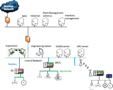
Figure 10.2. Example of logical mapping. For a color version of this figure, see www.iste.co.uk/flaus/cybersecurity.zip
After having carried out an inventory of the machines and their connection, it is useful to carry out an inventory of the applications dedicated to ICS and the communication flows between them. These applications include SCADA workstation HMI applications, data historian, PLC programs, etc.
For each application, the following elements can be listed:
- – the type of application;
- – the owner;
- – the number of users;
- – the equipment (physical or logical) required for this application to work;
- – the services listening on the network and associated ports;
- – the data flows between applications;
- – the version of the application.
A graphical representation can be made to show the different applications and the flows between them. These data are used to define zones and configure firewalls and other filtering or detection devices presented below.
Inventorying the various workstations, servers and equipment is a task that can be tedious and prone to error. In the IT world, there are tools available that can identify the workstations and running applications. In the OT world, this is not always possible, as equipment operating systems, which may be old or limited in functionality, do not always allow it.
However, a number of network tools can be used, such as arp-scan. In addition, commercial or open source tools with a graphical interface, such as Grassmarlin (Figure 10.3) (NSA 2017), are beginning to emerge.

Figure 10.3. Grassmarlin screenshot. For a color version of this figure, see www.iste.co.uk/flaus/cybersecurity.zip
10.2. Architecture security
10.2.1. Presentation
Most of the networks encountered use the TCP/IP protocol, which also supports industrial protocols such as Modbus, as presented in Chapter 2. Packet routing is based on the Address Resolution Protocol and is relatively easy to bypass. Remember that on a local network, one machine can pretend to be another machine (MitM attack, Chapter 4) and, since the protocols are not secure, it is easy to corrupt the frames exchanged between the equipment. It is therefore very important to isolate as much as possible the industrial control system (ICS) local network from other external networks (IT or Internet in particular).
In the context of an ICS, the design of a secure architecture involves a partioning into zones, with flows between each zone being filtered and monitored. In addition, activity in an area can also be monitored.
10.2.2. Secure architecture
Before the 1990s, ICSs were not connected to the entreprise information system network. The risk of computer attacks was controlled through isolation, and physical access or intrusion was required to compromise a system. The convergence of OT and IT has made this approach obsolete.
The objective of a secure architecture is to provide the best possible isolation between IT and OT so that vulnerable protocols and equipment in ICSs are as little exposed as possible.
The basic approach for securing ICS is the defense-in-depth approach. It uses methods such as the implementation of zones and conduits recommended by IEC 62443 to secure communications between trusted spaces.
Purdue’s model has been presented in Chapter 2 and serves as the basis for proposing a secure architecture (Figure 10.4). In order to secure exchanges between the IT and OT zones, and to facilitate firewall configuration, a demilitarized zone (DMZ) is often added between levels 3 and 4.
A DMZ is a physical and logical subnetwork that acts as an intermediary between the OT and IT networks. It adds an additional security layer to an organization’s local network: IT equipment exchanges with DMZ area equipment, and OT equipment exchanges with DMZ area equipment.
By placing resources accessible from the IT network in a DMZ, no direct communication is required between the OT zone and the IT zone. The firewall can prevent unauthorized packets from the IT network entering the OT network and can also filter traffic from other areas of the network, including the OT network. With a well-designed set of rules, a clear separation between the OT network and other networks with limited or even no traffic between the IT and OT networks can be maintained.
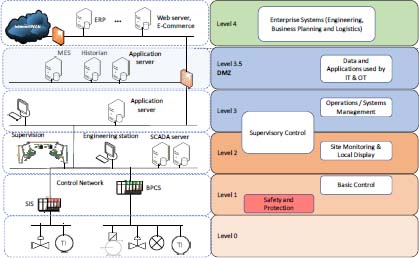
Figure 10.4. Architecture with a DMZ. For a color version of this figure, see www.iste.co.uk/flaus/cybersecurity.zip
The main security risk in this type of architecture is the compromise of a computer in the DMZ that is used to launch an attack against the OT network via authorized application traffic from the DMZ to the OT network. This risk can be reduced by regularly hardening and updating servers in the DMZ, and by configuring the firewall with rules that only allow connections initiated by OT network devices to the DMZ.
10.2.3. Partitioning into zones
A security zone is a physical and/or logical grouping of resources or grouping of resources with similar security requirements. This concept is defined in particular in IEC 62443 (Chapter 7). Physical zones are defined by grouping resources according to their physical location. Logical or virtual zones are defined by grouping resources according to functional criteria or by analyzing communications with a given protocol. To define the zones, the physical and functional model of the control architecture (mapping) developed during the asset identification phase is used.
A security policy for each area must be defined. It is possible to define areas within areas, which makes it possible to set up a defense in depth.
Information must be able to flow within a security zone and from a security zone to the outside and, conversely, from the outside to the inside. Even in a non-networked system, some communication exists (for example, intermittent connection of programming devices to create and maintain systems or transport of information via USB sticks). These communications to and from the outside define the entry and exit points of a zone. The resources used for communication can be grouped into a specific zone, called a “conduit”.
A conduit can be a single service (i.e. a single Ethernet network) or can consist of multiple data carriers (multiple network cables and direct physical access). As with zones, they can be physical or logical constructions. Conduits can connect entities in a zone or connect different zones.
The structuring of a system into zones and conduits makes it possible to define a level of security suited to each zone and to set up devices at the level of the conduits to limit propagation of the effects of a feared event in the same way as the watertight compartments of a ship, and then to set up a defense in depth by interlocking the zones and the conduits.
The zone concept goes beyond Purdue’s reference model. This model has been proposed to organize the integration of IT and OT. The division into zones and conduits has a different objective of structuring the system in relation to security requirements.
To define the zones, we start from the physical diagram of the architecture, organized if possible according to the Purdue model. A first level of partitioning is the breakdown according to levels.
The rest of the breakdown is carried out by analyzing the functionalities of the different elements and the protocols used. The different phases from operation to maintenance and configuration are reviewed. Subfields can be created if necessary. In addition, some resources are grouped into specific zones: safety instrumented systems (SIS), wireless equipment, temporarily connected equipment (programming console) and equipment connected via unsecured networks such as remote equipment.
When a resource supports several functions, it will be assigned to an area corresponding to the most restrictive function requirement, or a separate area will be created with a specific security policy. If, for example, several applications involving different activity levels are running on a single physical server, a logical zone can be created. In this case, access to a particular application is limited to users with privileges for that application level. An example is a single machine running an OPC server and analysis tools based on the OPC client. Access to the OPC server is limited to users with higher level privileges, while access to spreadsheets using the OPC client plug-in is available to all users.

Figure 10.5. Example of division into zones and conduits. For a color version of this figure, see www.iste.co.uk/flaus/cybersecurity.zip
10.3. Firewall
A firewall is a device that allows the partitioning policy to be applied between two zones. It makes it possible to filter the data flows, to monitor them and to log them. There are two types of firewalls: network firewalls and firewalls installed on hosts, for example, related to the operating system. The operating principles are identical, but securing the architecture is mainly based on network firewalls.
The fundamental technical function of any network firewall is to filter Transmission Control Protocol (TCP)/Internet Protocol (IP) communication packets. It is configured by defining rules, which can use source or destination addresses or ports. The firewall inspects each packet it receives to determine if it meets the rules. For example, traffic that does not come from a defined source can be blocked. A firewall is used at the border of an area. Rules can, for example, limit traffic to a single server, or allow it only with certain types of workstations, such as maintenance workstations.
The security provided by a firewall is closely linked to the accuracy of configuration rules. In general, for IP flows, identified by source IP address, destination IP address, protocol (e.g. UDP or TCP) and, if applicable, source and destination port numbers that are related to the type of application, the principles are as follows:
- – anything that is not explicitly allowed is prohibited or, in other words, flows are refused by default;
- – only the flows necessary for the functioning of the industrial system are allowed;
- – rejected flows must be logged and analyzed;
- – all incoming and outgoing flows in the industrial system must be logged.
In the case of an industrial system, exchanges between IT and OT parts must be kept to a minimum.
When a DMZ is used, it is possible to configure the system so that no traffic is allowed between the two zones: it ends up on the servers of the DMZ zone. For example, IT network workstations communicate with the DMZ historian server using an http protocol, whereas OT network equipment communicates with this server using Modbus.
This approach allows a protocol break and significantly increases security. Table 10.2 summarizes the configuration rules. It should be noted that rules 9–11 concern the security of the firewall itself, which should not be neglected.
In the case of industrial systems, there are firewalls that inspect the contents of the packet and are able to recognize industrial protocols. In addition to analyzing source and destination addresses and port numbers, the firewall analyzes the content of the frame. It is, for example, able to decode the Modbus protocol and recognize the type of function, the address written or read and the data sent. This is called Deep Protocol Inspection (DPI). From the configuration of the PLCs and the SCADA, it is possible to define rules on these elements. For example, rules can block writing to a memory area, or limit the values of a command to a maximum threshold. A number of commercial products implement these features, as well as open source software such as Snort, Suricata or Bro presented below.
Table 10.2. Configuration rules
| No. | Rules and regulations |
| 1 | All the basic rules must be “block everything”. |
| 2 | All authorized flows must be specific to the source and destination address, as well as port numbers, and stateful if necessary. |
| 3 | Any direct traffic between the control network and the corporate network should preferably be blocked. All traffic should end in the demilitarized zone. |
| 4 | Flows between the control network and the corporate network can be authorized on a case-by-case basis, after risk analysis. |
| 5 | Any protocol allowed between the control network and the demilitarized zone should not be explicitly allowed between the demilitarized zone and the corporate networks (and vice versa) in order to ensure a protocol break. |
| 6 | All outgoing traffic from the corporate network to the control network should be restricted by source, destination and port filtering. |
| 7 | Outgoing packets from the control network or demilitarized zone should only be allowed if they have a correct source IP address that is assigned to the control network or devices in the demilitarized zone. |
| 8 | The devices of the control network must not be directly connected to the Internet, even if the area is protected by a firewall. |
| 9 | All firewall management traffic must be carried out either on a separate secure management network or on an encrypted network with multifactor authentication. Traffic should also be limited by IP address to specific management stations. |
| 10 | All firewall policies should be tested periodically. |
| 11 | All firewall configurations must be backed up immediately before commissioning. |
Remote access is an important issue for firewall rule management. It is very common for remote access to be required for maintenance by suppliers or integrators, or even for remote operation. Access must be managed with an appropriate authentication system, usually multifactor, and a secure network, such as a virtual private network (VPN). The access management server must be placed in the DMZ or be part of the IT infrastructure. It may be useful to set up a second level of authentication to access the OT network.
10.4. Data diode
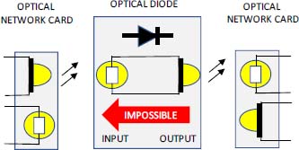
Figure 10.6. Principle of a data diode. For a color version of this figure, see www.iste.co.uk/flaus/cybersecurity.zip
A data diode, also called a “unidirectional gateway”, is a device that allows data to move only in one direction. The system can be software or hardware, for example based on an optical system, which guarantees the blocking in the opposite direction.
A data diode is required for Class 3 facilities in the ANSSI classification. A data diode can be coupled to a software device to replicate databases and emulate a server.
A data diode can be used to let the data pass only in the OT to IT direction to upload production data. Bidirectional communication can be achieved using multiple data diodes and a DMZ with protocol break, which is well suited for securing IT/OT connections.

Figure 10.7. Example of an architecture with data diode, firewall and industrial firewall. For a color version of this figure, see www.iste.co.uk/flaus/cybersecurity.zip
10.5. Intrusion detection system
10.5.1. Principle of operation
Intrusion detection consists of monitoring events occurring in a computer system or network, and analyzing them in order to detect possible incidents that constitute violations of security rules or policies, or imminent threats to the information system or installation.
Incidents have many causes, such as malware (e.g. viruses or spyware), malicious users accessing systems from the Internet and authorized users of systems who abuse their privileges or attempt to obtain additional privileges.
Although many incidents are malicious in nature, some are not and may be human errors.
There are two types of intrusion detection systems:
- – Network intrusion detection systems (NIDS) that monitor network flows;
- – intrusion detection systems installed on workstations that monitor workstation activity (host-based intrusion detection system [HIDS]).
A NIDS collects network traffic using one or more probes, and analyzes it according to protocol, type, source, destination, etc. It is deployed to be able to monitor traffic entering and leaving the network area (Figure 10.8), and looks for certain activities that may be hostile actions or misuse, such as denial of service attacks, port scans, malicious content in data packets (Trojan, viruses or worms, etc.), brute force attacks, etc. An NIDS can eventually block traffic: this is called an intrusion protection system (IPS).
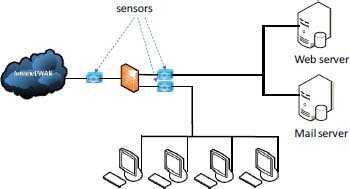
Figure 10.8. NIDS. For a color version of this figure, see www.iste.co.uk/flaus/cybersecurity.zip
The advantage of a NIDS is to provide intrusion detection coverage with fewer system resources and with generally lower deployment, maintenance and update costs than a HIDS. In addition, it has visibility over all network traffic, and it can correlate attacks between several systems. The disadvantages are related to the need to set up a large number of probes, a secure network to collect information and a relatively high processing capacity to avoid slowing down operation.
Another limitation to be aware of is that a NIDS is ineffective when traffic is encrypted.
Intrusion detection systems can also be deployed on hosts, workstations or servers (Figure 10.9). This implementation is called HIDS. A HIDS examines log files and looks for events such as connections at strange times, connection authentication failures, addition of new user accounts, changes or access to critical system files, changes or deletions of binary (executable) files, starts or stops of particular processes, attempts to increase privileges or use certain programs. It also examines network traffic entering or leaving a specific host, with some also supporting specific applications (FTP or web services).

Figure 10.9. HIDS. For a color version of this figure, see http://www.iste.co.uk/flaus/cybersecurity.zip
These systems are beneficial but heavy to deploy and less well suited to ICS, where the main focus is on monitoring network traffic, and where there are many devices on which to deploy HIDS is not possible. In many cases, a combination of both approaches is used.
The general structure of the processing modules of an intrusion detection system (IDS) is shown in Figure 10.10. The data come from network traffic or host activity. The analysis engine uses these data and knowledge about the attack profile or normal system behavior to detect an intrusion. The alerts generated can be transmitted to a Security Information and Event Management (SIEM) that provides real-time analysis of security alerts generated by applications and network equipment. This system is described in the following section.
IDSs are systems used for monitoring, which is the third function of the NIST cybersecurity framework presented in Chapter 11.
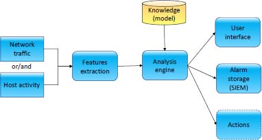
Figure 10.10. Structure of an IDS. For a color version of this figure, see http://www.iste.co.uk/flaus/cybersecurity.zip
10.5.2. Detection methods
To detect incidents, an IDS uses knowledge or a model, which can represent normal or abnormal behavior:
- – in the first case, the model describes the normal behavior and detection is based on the search for anomalies in relation to this behavior; we speak of an anomaly-based system;
- – in the second case, the model describes behaviors characteristic of an intrusion and is referred to as a signature-based method.
Models are built by experts or by automatic machine learning methods.
If the model is inadequate, for example if the signature is missing or inappropriate, or if normal behavior is not captured correctly, then the IDS can generate an alarm for benign traffic that is not hostile, this is called a false positive. Similarly, hostile activity, which does not match an IDS signature or resembles normal activity, may be undetected, this is called a false negative (false sense of security).
This imperfect functioning is an important limitation to the use of IDS because it can be perceived as a system generating disturbances due to false positives. This is also the reason why IPS mode operation is almost never used, as the risk of interrupt normal operation is too great. This is especially true for industrial systems.
Detection approaches are presented in more detail below. Many IDSs use both approaches, either separately or in an integrated way, to improve performance.
10.5.2.1. Signature-based approach
The idea is to describe what is known to be representative of an attack by a model called a signature, and to monitor network traffic to find matches to these signatures. There are signatures:
- – based on content such as, for example, character sequences such as/etc./passwd in a telnet session;
- – context-based, such as a signature that corresponds to a potential intruder performing a scan to find open web servers, or a signature that identifies a Nessus scan, or a ping flood attack.
Signature-based detection is very effective in detecting known threats, but it is ineffective in detecting unknown threats or many known threat variants. Signature-based detection technologies have a poor understanding of many network or application protocols, and cannot track and understand the status of complex communications. For example, signature-based IDSs cannot associate a request with the corresponding response, such as knowing that a request to a web server for a particular page has generated a response status code of 403, which means that the server has refused to respond to the request. Nor do they have the ability to remember previous requests when processing the current request. This limitation prevents signature-based detection methods from detecting attacks that include multiple events, if none of the events contains a clear indication of an attack.
In addition, to apply this approach in the case of an ICS, the attack signature database must have different characteristics from those of signatures in an IT-oriented database. In particular, signatures must take into account industrial protocols.
IDS and IPS providers develop and incorporate attack signatures for various ICS protocols such as Modbus, DNP3 and IEC 60870.
10.5.2.2. Anomaly-based approach
Anomaly-based detection consists of comparing the observed activity with a model of the activity considered normal. An IDS using anomaly-based detection has profiles or models that can represent the normal behavior of users, hosts, network connections or applications.
The first question to ask in order to implement such an approach concerns selection of the characteristic elements of the activity. These may include raw network data, protocol behavior (state), substation activity indicators, or even cyber-physical system behavior characteristics. The latter possibility, detection of anomalies with respect to the cyber-physical system model, is discussed in the following section.
The second question concerns the methodology for constructing the model: specification by the analyst or automatic learning and, in the latter case, choosing the learning method (Flaus and Georgakis 2018b), which can be a statistical or deep learning approach for example, and then defining the periods during which the activity is considered normal and representative.
Among the advantages of anomaly-based detection approaches are, first of all, their adaptability to both unknown and internal attacks. For example, it is possible to quickly detect an internal attack (using a compromised user account, for example), because the behavior will be unusual. In addition, an attacker never knows what may or may not generate an alarm, making detection more difficult to circumvent.
Disadvantages include the need for a high initial preparation time, the fact that there is no protection during initial learning, the difficulty of characterizing normal behavior and the interpretation of false positives or false negatives, which can be difficult. This approach is still not widely used in commercial products.
10.5.2.3. Practical tools
There are IDS software programs available that can analyze the traffic of industrial systems such as Snort, Suricata or Bro. Snort rules have been developed for Modbus TCP, DNP3 and IEC 60870. Snort is an open-source intrusion detection and prevention system that uses rule-based language to perform inspections based on signatures, protocols and anomalies. Rules for DNP3 and Modbus protocols have also been added to the Bro IDS platform.
Ossec is an open-source HIDS system that performs log analysis, file integrity analysis and many other parameters.
10.5.3. Intrusion detection based on a process model
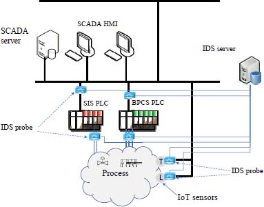
Figure 10.11. Structure of an industrial IDS. For a color version of this figure, see http://www.iste.co.uk/flaus/cybersecurity.zip
For cyber-physical systems, in particular ICS, there is a specific detection approach based on the detection of anomalies in relation to the behavior of the physical system model or the control system.
This method is based on the assumption that an attacker’s objective is to put the target system in a critical state, so by monitoring the evolution of the cyber-physical system and detecting the occurrence of critical or precritical states, it may be possible to detect attacks. These techniques are based on a model of the physical system and the control system. They are based on ideas similar to those developed for monitoring and diagnosing physical systems.
This approach has developed in recent years, and applications have been proposed in different fields such as chemistry (Cárdenas et al. 2011; Fovino et al. 2012), water treatment (Hadziosmanovic et al. 2014), electricity distribution (Liu et al. 2011) and even medical systems (Hei et al. 2013).
From an operational point of view, the following elements are necessary to monitor and analyze the evolution of a system:
- – a representation language to formally describe the physical system and critical states;
- – a system for monitoring or reconstructing the current status of the monitored system;
- – a critical state distance metric to calculate the proximity of a state to critical states;
- – a detection and possibly prognostic algorithm to decide whether or not the system is evolving toward a critical state.
Different possibilities exist to implement these features. The difficulties encountered with this type of approach are the need to develop a model of the system, which must be robust, and the management of uncertainty regarding the gap between the modeled behavior and the actual behavior. The first point is a limitation that is all the more important as systems often evolve and the model must therefore be readjusted. Dedicated automatic learning can be a solution (Patents, Université Grenoble-Alpes 2018).
10.6. Security incident and event monitoring
The various devices presented in the previous sections (firewall, IDS, data diode), workstations, servers, network equipment, ICS equipment, authentication systems, generate events that characterize the system status and incidents that occur. This information includes:
- – information on blocked traffic provided by firewalls;
- – intrusion detection alerts provided by IDSs;
- – unsuccessful login alerts from authentication systems;
- – information about identified malware provided by antivirus software.
The centralization and exploitation of this information is useful for monitoring the security of an ICS. This is the role of SIEM.
The functionalities of these systems are as follows:
- – generation of centralized views, which are generally presented in the form of dashboards;
- – normalization of received events, on the one hand, by translating them into a standard and readable format, and, on the other hand, by grouping them according to the categories defined by the configuration;
- – correlation of events: from predefined rules, it is possible to generate alerts. This can be done on historical data or in real time. An example of rules can be “if more than five unsuccessful logins in 5 min then generate an alert”;
- – reporting and alert: different ratios can be calculated, evolution curves can be plotted and, from the sequence of pasted events and depending on the ratios, alerts can be generated;
- – log management: this allows events and logs to be stored in a central database, while ensuring the quality of storage and the compliance of storage conditions to requirements.
In addition, it may be useful to compare the observed situations to during a situation defined as being “normal”. To do this, a SIEM can be used to define a baseline behavior.
There are a number of open-source tools available to implement a SIEM. Examples include the ELK stack or the OSSIM software.
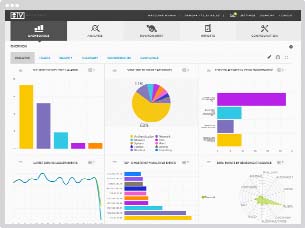
Figure 10.12. SIEM screen. For a color version of this figure, see http://www.iste.co.uk/flaus/cybersecurity.zip
10.7. Secure element
IIoT equipment has particular vulnerabilities compared to conventional equipment such as PLCs:
- – from a material point of view, they are more easily accessible and can be the subject of physical attacks such as auxiliary channel attacks based on power consumption analysis (Chapter 4);
- – from a software point of view, they are programmed using traditional computer languages, less constrained than the languages used on PLCs, which can lead to the creation of software with significant vulnerabilities;
- – they are based on generic elements (COTS), which can potentially be corrupted in the supply chain and, for example, contain backdoors.
Systems are not frozen, which poses the problem of adding the device to the network and removing them.

Figure 10.13. SoC with security element. For a color version of this figure, see http://www.iste.co.uk/flaus/cybersecurity.zip
In order to secure a system with an IIoT device, it is necessary to carry out the following:
- – the authentication of the device;
- – the security of data transfers;
- – securing the storage of sensitive data on the device;
- – provide a secure code execution environment.
The solution is to use a secure element (SE), defined as a tamper-proof platform (usually a secure microcontroller on a chip), capable of securely hosting applications, and storing their confidential and cryptographic data in accordance with the security rules and requirements defined by a set of clearly identified trusted authorities.
A SE is used, for example, to store a device’s private key as well as security certificates. To be as safe as possible, it is preferable that it be integrated into the System-on-a-Chip (SoC) itself (Figure 10.13). Indeed, the use of an external circuit is vulnerable to auxiliary channel attacks by observing the transit between the SE and the main circuit.
A secure SoC provides some or all of the following features:
- – secure key storage: the keys can be stored in unmodifiable read only memory (ROM) memory at the time of manufacture or in flash memory during configuration. The storage must resist physical attacks (side channel attacks, for example);
- – secure boot: the boot code must also be securely stored in a non-editable memory (ROM). This code is considered secure (root of trust). On power-up, the processor starts executing the boot code. Its main task is to start the application code after verifying its signature (Appendix 1). This allows a secure boot;
- – secure firmware/software update: the update of the device is carried out in a secure way using signature and, possibly, encryption mechanisms for confidential data;
- – Data at Rest Protection (DARP): in the event of physical access to the device, the data must not be readable. The device must therefore be able to encrypt the data stored in flash memory or RAM;
- – crypto-processor: in order to be able to easily implement data encryption, it is desirable that it be implemented by hardware functions;
- – Trusted Execution Environment (TEE): a TEE is a set of mechanisms at the main processor level that provide secure isolation of libraries and sensitive data. This secure environment ensures that data are stored, processed and executed as planned (Bar-El 2010). The purpose is to avoid any attack on this code, or that sensitive keys or secret data are not read;
- – true random generation number: an electronic circuit is used to produce encryption keys that are impossible to predict. The generation of random numbers is useful for cryptographic algorithms;
- – unique identifier: it is essential to be able to identify the device in a secure and unique way. Storing an identifier designed to be unique and secure in the SoC is an ideal solution.
In addition, it is desirable that the system should have functionalities to facilitate safety management. Indeed, when a large number of devices are deployed, a centralized safety management system is required. The latter interrogates each device, which must be able to provide adequate information on its characteristics, its condition and any security events.
Depending on the functionalities implemented, the SoC can be used to meet the basic, enhanced or critical levels defined by the Industrial Internet Consortium’s good practices (Chapter 6, section 6.9).