1
Components of an Industrial Control System
1.1. Introduction
1.1.1. Definition: automated and cyber-physical systems
The systems we are interested in are automated systems in the broad sense: they consist of a computerized control system, sensors to access physical quantities and actuators to act on the controlled system.
Such systems are found in industrial production facilities, where control is carried out by a programmable logic controller (PLC) or by a set of connected objects. There are also such systems for the automation of buildings, water and electricity distribution networks, transport systems, etc. They have a computer part constituting an information system (IS) and a physical part. We are talking about a cyber-physical system (CPS).
1.1.2. Definition: Information System (IS)
An Information System (IS) is an organized set of resources (hardware, software, personnel, data, procedures, etc.) for acquiring, processing and storing information (in the form of data, text, images, sounds, etc.) within and between organizations.
Many ISs only process information, others affect the physical world. It is the latter that we are interested in this book.

Figure 1.1. Information system. For a color version of this figure, see www.iste.co.uk/flaus/cybersecurity.zip
1.1.3. Definition: industrial IS or ICS
An industrial IS, or an industrial control system (ICS), is a system composed of an IS plus specific equipment for control and measurement.
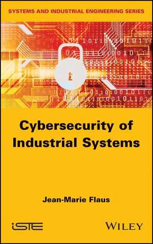
The architecture of a traditional industrial IS is shown in Figure 1.2, which is called Supervisory Control And Data Acquisition (SCADA) or Distributed Control System (DCS).
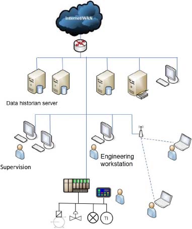
Figure 1.2. Industrial information system. For a color version of this figure, see www.iste.co.uk/flaus/cybersecurity.zip
The architecture of an industrial IS based on the Internet of Things (IoT) is shown in Figure 1.3. It is based on the Cloud and introduces new components and protocols described in the rest of the book.
In general, an ICS is composed of the same elements as a management IS with, in addition, specific equipment and specific software such as control command programs. These ensure real-time control and manage the archiving of data that characterize the evolution of the installation (history and alarm logs).
Henceforth, we will use the term ICS to refer to all the computer systems used to control a physical system.
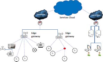
Figure 1.3. IIoT information system. For a color version of this figure, see www.iste.co.uk/flaus/cybersecurity.zip
1.1.4. Definition: IT and OT system
To distinguish ICSs from management ISs, the terms Information Technology (IT) and Operation Technology (OT) are often used.
An IT system is an IS as presented above. It is intended for the processing and storage of information. It is composed of computers, software, networks and human–machine interfaces (HMIs). An OT system is intended to interact with a physical system. It is composed of hardware and software to capture the evolution of a physical system via sensors, and to perform actions via actuators.
ICSs rely on varied information processing equipment, but integrate additional equipment to act on physical systems, and therefore belong to the OT world.
1.1.5. Definition: SCADA
A SCADA (Figure 1.4) is a system for controlling automation and data acquisition equipment. It makes it possible to centralize the control of an installation and to present an ergonomic HMI.
It includes workstations that generally run on Windows and are equipped with specialized software with a graphical interface that displays synoptics and trend curves. These workstations are connected via a network to equipment directly linked to the physical system: PLCs, input–output components, remote HMI, etc. It also includes servers, routers and other useful technical equipment. A SCADA is an ICS, but not all ICSs are SCADAs.
Figure 1.4. The minimal functions of a SCADA. For a color version of this figure, see www.iste.co.uk/flaus/cybersecurity.zip
1.1.6. Definition: Distributed Control Systems (DCS)
A DCS is a set of control systems connected in a network with a central unit to carry out supervision. The whole set is from the same manufacturer. Historically, this architecture was very different from the more heterogeneous SCADA systems, but with the evolution of technology, the differences have faded.
1.1.7. Definition: Industrial Internet of Things (IIOT)
The IoT refers to the extension of the Internet, that is, the global network for exchanging information with objects connected to the physical world. The Industrial Internet of Things (IIoT) is the use of the IoT in the industrial sector. These objects, more or less autonomous, will transform the industrial world. We sometimes talk about the plant of the future or Industry 4.0. The potential of this technology is enormous. The challenges posed by this interconnection are commensurate with the potential of this technology.
1.1.8. Different types of ICS
ICSs are used in many industrial sectors and critical infrastructures. A distinction is made between the manufacturing sector (e.g. the chemical industry or building management systems) and the distribution sector (e.g. of water or energy).
In the first case, the installation is geographically located. The manufacturing processes can be:
- – continuous: these processes operate continuously, often with transitions to produce different qualities of a product, the quantities handled are real quantities. They are found in the chemical or petroleum industries;
- – batch: these processes have distinct processing steps, performed on a given quantity of material. There is a separate start and end step for batch processing, with the possibility of short steady-state operations during the intermediate steps. Typical batch manufacturing processes include the manufacture of drugs or food;
- – discrete: these systems generally perform a series of steps on a single device or a succession of machines to create the final product. The assembly of electronic and mechanical parts and the machining of parts are typical examples of this type of industry.
In the distribution sector, ICSs are used to control geographically dispersed assets, often over thousands of square kilometers, including water distribution systems, wastewater collection systems and energy management systems.
As explained above, an industrial IS is composed of elements similar to a traditional IS (workstations, servers, network equipment, printers, storage and backup systems) but also of specific elements designed to manage interaction with the physical system and provide an appropriate HMI: these include the PLC, remote terminal units (RTUs) and the acquisition system.
1.2. From the birth of the PLC to the SCADA system
Until the late 1960s, control and regulation of industrial manufacturing systems was carried out by mechanical or electromechanical relay-based systems. In 1968, Dick Morley, an engineer at GM, proposed the concept of a PLC, which he called Modicon (MOdular DIgital CONtroller). It is interesting to note that his motivation was to offer an alternative to minicomputers, whose prices were beginning to fall but which remained very complicated to program for the control of industrial systems. The cultural difference between the IT and OT world is therefore rooted in the very birth of the PLC.
The communication possibilities appeared in 1973, with the evolution of the 084 model into the 184 model. The first protocol developed was the Modbus protocol, from Modicon. Because of it, an automaton could communicate with other automatons and be very far away from the machine it was controlling. One of the first microprocessors was introduced in 1974 (Intel 8080) and, in 1975, Modicon introduced the 284, the first microprocessor-based device.

Figure 1.5. Allen Bradley – Modicon 084. For a color version of this figure, see www.iste.co.uk/flaus/cybersecurity.zip
The need to “supervise” the PLCs from a central station, based on a microcomputer, quickly became apparent. This resulted in an architecture composed of a PLC, directly connected to sensors and actuators running an “automation” program or performing PID control, and a system equipped with an HMI, which presents a synoptic of the system to be controlled and the trend of the evolution of the variables, archives data on mass storage and allows the program to be sent to the PLC. All the main functions of SCADA are present in this architecture.
ICSs then became more and more complex, which could be distributed over several sites. The solutions that have emerged have been classified into homogeneous solutions that are specific to a single manufacturer (i.e. DCS) or heterogeneous solutions consisting of PLCs, workstations and supervision software from different manufacturers (SCADA). Traditionally, homogeneous solutions are more commonly used in the process industry, whereas others are often used in the manufacturing industry. With the evolution of technology, the differences between the two types of solutions have narrowed and we talk about SCADA systems in a global way.
1.3. Programmable logic controller (PLC)
A PLC provides an essential function in a system’s automation: it makes it possible to modify, trigger or modulate physical actions according to measured quantities, either by following a predetermined sequential operation, or by controlling or regulating quantities according to a fixed set point. These functions are those of the Basic Process Control System (BPCS). It operates in real time, in parallel with the evolution of the physical system. Loss of this ability to respond in real time to changes in the physical system is a problem, as there is a risk of unwanted evolution, and this represents a potential vulnerability.

Generally, a PLC consists of a processing unit, a memory unit, a power supply unit, input/output interfaces and a communication interface. It can be connected to a programming device that is either a specific console or, in most cases, a PC workstation. As mentioned above, a PLC is a computer system with deliberately limited possibilities in order to make its implementation easier.
The architecture of a PLC is similar to that of a microcomputer without an HMI:
- – the microprocessor-based central unit runs the program, reads the input signals and writes the output signals;
- – the memory contains the PLC operating system, the system control program and the related data;
- – the programming device is used to load the program into memory and access certain data areas;
- – the input module makes it possible to receive signals from the system to be controlled. These can represent on-off values, for example, indicating that a switch is open or closed, or values that continuously vary within a range of values, for example, to describe a temperature. These signals can be received or transmitted as an electrical or computer signal via a field bus1 using a specific protocol such as those described in Chapter 2 (EtherCat, CAN, Modbus, Profibus, Profinet, Ethernet/IP, etc.);
- – the output module performs the reverse operation, and it transforms the outputs calculated by the PLC program into electrical or computer signals;
- – the communication interface allows the PLC to communicate with the other PLCs, the supervision system (SCADA) and the programming station. Nowadays, it is often an Ethernet network interface.
From a functional point of view, a PLC is the basic equipment for the control and regulation of physical systems. There are two main types of features:
- – the regulation of continuous systems;
- – the automation of sequential systems.
In the first case, the objective is to bring a physical quantity to evolve according to a desired (possibly constant) profile. The system measures the controlled quantity in a relatively small period of time, in an almost continuous way, and calculates one or more values of the actions to be applied to the physical system to bring the controlled value to the desired value. This is the case, for example, of a temperature regulation that can be modulated by opening a heat transfer fluid valve to obtain a desired temperature.
In the second case, the PLC performs actions from on–off inputs. It can either perform actions according to measured quantities, for example shutting off a valve, if a container is filled or perform action sequences to control a device depending on the measurements and a manufacturing recipe.
In all cases, a PLC operates on a regular cycle (in the order of 10–100 ms), during which it reads the values of the inputs it copies to the input memory (IM), then executes the program, puts the results into the output memory (OM) and sends these values to the physical device (Figure 1.7). The image of the state of the physical device is therefore stored in the PLC’s memory. This cycle also includes various operations to ensure the proper functioning of the system: integrity test of the I/O module, verification that the user program is not modified, verification that the system is not blocked via a watchdog and communication operations via the interface to the remote modules, the programming station and the HMI interfaces.

Figure 1.7. Execution cycle
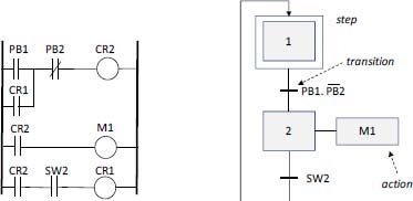
Figure 1.8. Example of LD and SFC language
To simplify the use of PLCs and to remain as close as possible to the electromechanical systems mentioned in the introduction, a number of specific languages have been defined. They are described in IEC 61131/3. They are as follows:
- – The ladder diagram (LD) (Figure 1.8);
- – The functional block diagram (FBD);
- – The sequential function chart (SFC) (Figure 1.8) ;
- – The structured text (ST), close to the PASCAL language;
- – The instruction list (IL), close to the assembler.
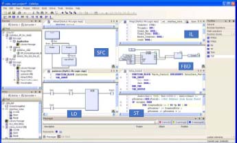
Figure 1.9. Programming languages IEC 61131/3. For a color version of this figure, see www.iste.co.uk/flaus/cybersecurity.zip
Malware can be written directly in these languages (Govil et al. 2018). The loading of the program into the PLC is not very secure, so this is a major vulnerability.
These languages can either be interpreted by the PLC or compiled on the development station and uploaded to the PLC. When considering cybersecurity, it should be taken into account that a lower level computer system is required to run them on the PLC. Most of those available on the market, whether PLCs, RTUs, safety instrumented systems (SISs), or DCSs, now have a commercial operating system. Here, for example, are some used by major manufacturers:
- – Schneider Quantum: VxWorks;
- – Siemens: VxWorks from 2014;
- – Allen-Bradley: PLC5: Microware OS-9, Controllogix: VxWorks;
- – Emerson DeltaV: VxWorks.
The vulnerabilities of these operating systems are therefore vulnerabilities for the equipment that uses them, and several manufacturers can be affected by the same malware. An example is the ICSA-15-169-01 (TCP Predictability Vulnerability) vulnerability that affected VXWorks. Such a system is used on more than 100,000 devices connected to the Internet2, as well as on systems as diverse as network routers, the Boeing 787 Dreamliner or the Gran Telescopio Canarias telescope.
1.4. RTU, master terminal unit and intelligent electronic device
A Remote Telemetry Unit (RTU) is a microprocessor-controlled electronic device that connects a physical system to a master system, typically a PLC, master terminal unit or SCADA. It transmits telemetry data and receives messages to control the physical system. Communication is often provided via a modem, cellular connection, radio or using communication technology for long distances. Often, the available electrical energy is limited, for example energy from solar panels, and this is one of the constraints to be respected for these systems.
An RTU may also be called a remote control unit. From a cybersecurity perspective, these systems have vulnerabilities similar to PLCs, are sensitive to vulnerabilities on the link and are physically vulnerable because they are isolated.
In the field of electrical power distribution, the remote control units used to control the distribution are called intelligent electronic devices (IED). For example, they act on circuit breakers or transformers.
1.5. Programmable Automation Controller
The term Programmable Automation Controller (PAC) was introduced in the early 2000s. A PAC is a PLC with extended capabilities. It offers more processing possibilities: a greater number of PID control loops, advanced control possibilities (fuzzy controller, predictive control, etc.), batch control modules and even dedicated business modules. It also has more connectivity and can manage remote modules similar to RTUs.
With technological developments, PLCs have become more and more sophisticated and the boundary between PLCs and PACs is blurred. This term is often used in IIoT architectures.
1.6. Industrial PC
An industrial PC is a classic PC reinforced from a hardware point of view and often supplied in a chassis adapted to the industrial world (rackable and fanless, for example). It often has a larger number of inputs/outputs (I/Os), and some of them have specific possibilities, such as analog ports. It can use a traditional operating system, a dedicated system such as Windows Embedded or a real-time operating system (VxWork or FreeRTOS, for example).
1.7. Safety instrumented systems
An SIS (Goble and Cheddie 2005) is defined as a system composed of sensors, logic processing and actuators designed for:
- – ensuring that an industrial process evolves automatically to a safe state when specified conditions are violated;
- – allowing a process to evolve safely when the specified conditions allow (permissive functions);
- – take measures to mitigate the consequences of an industrial hazard.
Given the importance of an SIS to the safety of a facility, it is designed so that its probability of failure is less than a value based on the severity of the impact of a loss of control. This approach, carried out as part of the functional safety study, is described in Chapter 8.
From a technological point of view, SISs are often built using specific PLCs, with reinforced and redundant hardware. One example is the Triconex3 brand, which markets such devices. The functions performed by the SIS are critical to the security of a facility. If the BCPS fails to maintain the system in a safe area, the SIS must take appropriate action. It corresponds to a level of defense-in-depth protection of the physical system (Figure 1.11).
SISs should, therefore, be considered with particular attention to cybersecurity. As these systems have the role of bringing the physical system back to a stable, safe state, they represent a particular challenge for a cyber attacker. A simple denial of service attack can significantly increase the level of risk of the system, since in the event of a BCPS malfunction, the security actions normally triggered by the SIS can be prevented and significant damages can occur.
It should be noted that SISs can also be the targets of attacks in order to create unintentional shutdowns of the production system. Indeed, as the SIS takes control of the normal control system, it is possible, by attacking it, to override the actions of the normal control system and cause the system to shut down.
It therefore appears that protecting the SIS is a priority in an ICS.

Figure 1.10. Safety instrumented system (SIS). For a color version of this figure, see www.iste.co.uk/flaus/cybersecurity.zip
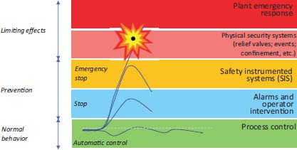
Figure 1.11. The position of the SIS in terms of protection level. For a color version of this figure, see www.iste.co.uk/flaus/cybersecurity.zip
1.8. Human–machine interface (HMI)
HMI is an essential part of ICSs. It allows the user to visualize how the system works and take the necessary actions. Once constructed physically, with entire walls covered with indicators, dials and adjustment buttons, it has been replaced by graphic screens, when technological developments have made it possible. Beyond ergonomics issues, the software and stations used by these HMIs are also a source of vulnerabilities. The HMI makes it possible to monitor the system by observing the different quantities and their evolution, as well as to control the system by launching sequences or modifying the setpoints. It is possible via these interfaces to act maliciously on the controlled system, and managing the access control to these stations, either physically or via a remote connection, is an important point for cybersecurity.
There are several types of HMI: the first are PC workstations running on a traditional operating system such as Windows and using software to present synoptics and trend curves. These software are often used in SCADA supervision stations. The vulnerabilities of these HMIs are those of traditional computer systems.
The second type of HMI is made up of dedicated units running on an embedded operating system such as Windows Embedded and, often, with a touch screen. They are often close to the physical system and can be more or less physically isolated. Cybersecurity issues are those related to embedded systems, one of the problems being to carry out updates in a systematic and secure way.
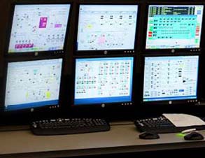
Figure 1.12. HMI on PC. For a color version of this figure, see www.iste.co.uk/flaus/cybersecurity.zip
HMIs interact directly with PLCs and servers of the ICS. The link and the protocol used can be a source of vulnerabilities.

Figure 1.13. Dedicated unit for HMI. For a color version of this figure, see www.iste.co.uk/flaus/cybersecurity.zip
1.9. Historians
In control systems for centralized (DCS) or heterogeneous (SCADA) industrial systems, it is useful to store a certain amount of information such as the evolution of the different values that have been collected from the sensors, the evolution of setpoints, alarms, the status of equipment, etc. These data are stored in specific databases, optimized for time series. Such software is marketed by companies offering complete ICS solutions such as ABB, Honeywell, Schneider, Siemens or by specialized companies such as Panorama4 or AspenTech5.
From a cybersecurity perspective, it should be noted that access to these databases is provided from both the OT and IT systems, and that this aspect must be taken into account, as it effectively introduces a connection between the two types of network.
1.10. Programming and parameter setting stations
The physical system is controlled by the PLC in real time. The program to be executed is developed in a programming environment dedicated to the brand of the PLC. For example, for Siemens S7 PLCs, there is the STEP 7 environment running on a PC. For Schneider PLCs, we find Unity Pro for the Modicon range, Concept for Quamtum, TwidoSuite for Twido.
These software programs make it possible to write the program in at least one IEC 1131-3 language, load or read this program to and from the PLC, read the PLC memory, perform various basic operations such as stopping or restarting, setting the time, and configure controller and automation parameters such as PID constants and timers (Flaus 1994).
These development stations and communication with PLCs are therefore interesting gateways for attackers. Malicious software capable of using the development system or intercepting communication with the PLC can very easily take control of it6. These workstations often run on Windows and have the vulnerabilities found on traditional computer workstations.
1.11. Industrial Internet of Things (IIoT)
The notion of the IoT (Minerva et al. 2015) is similar to that of CPS. It is defined by the NIST (Cyber-Physical Systems 2017) as an intelligent system that includes networks of physical and computer components that interact with one another.
IIoT devices are the end-points for the Internet of Things, those that are connected to the physical world. They are characterized by:
- – their acquisition and control capabilities, which ensure interaction with the physical world. Different types of sensors can measure a number of quantities (temperature, pressure, position, etc.) and are coupled to an analog-to-digital converter for acquisition. In the other direction, a digital-to-analog converter is used to control actuators (switches, motors, valves, etc.) or different output devices (LED, display, loudspeaker, etc.);
- – their processing and storage capabilities: a processor, which can be relatively powerful, is coupled with RAM and non-volatile flash memory;
- – their connectivity: an IoT device has features to connect to a network, either traditional (wired or Wi-Fi) or more specific like LPWAN (Chapter 2), for example;
- – their energy management: not all devices are connected to a power source and some operate on batteries, such as isolated sensors, or some HMI devices such as switches. Power can also come from ambient energy trapping and be limited;
- – their ability to be physically secured through a secure storage device, called a Secure Element. It is a tamper-proof hardware element, capable of securely hosting applications and storing confidential and cryptographic data;
- – their encryption capabilities, which depend on the processor’s computing capabilities, the presence or not of a dedicated circuit, and of the energy management.
Many ready-to-use devices called Component Off-The-Shelf (COTS), including microcontrollers and single board computers, are designed around integrated circuits called System-on-a-Chip (SoC), which include most of the features presented above. The available computing power is relatively high, with a frequency of about 100 MHz to several GHz, a flash memory of 32 MB to 1 MB and a RAM of at least 128 KB.
The equipment must be uniquely identifiable. Depending on the type of network used, identification systems can be:
- – unique identifiers stored in the device at the time of manufacture;
- – computer identifiers such as IP addresses or MAC addresses;
- – identifiers from the world of telephony: SIM card identifiers and mobile numbers;
- – Radio-Frequency Identification (RFID) or Near-Field Communication (NFC) identifiers.
These devices are often isolated and their physical vulnerability is significant. They are, therefore, exposed to attacks based on reverse engineering or physical attacks, such as auxiliary channel attacks on consumption, as described in Chapter 4.
1.12. Network equipment
The transfer of information between the different components of the ICS is ensured by network equipment, wired or wireless, to which the various equipment is connected.
It is important to note that these devices work with operating systems, either proprietary or derived from Linux (DD-WRT, for example) and are as vulnerable as other devices.
1.12.1. Switch and hub
Switches are the foundation of most corporate networks. Switches allow the different connected devices to communicate with each other. They manage the data flow on a network by transmitting a received network packet only to the devices for which the packet is intended. Each network device that is connected to a switch can be identified by its network address, allowing the switch to direct the flow of traffic while maximizing network security and efficiency.
There are remotely manageable switches, which is an additional potential vulnerability for these devices. Some are able to copy streams and transmit them to an intrusion detection system.
1.12.2. Router and gateway
A router is a network device that transfers data packets between computer networks. Routers perform Internet traffic management functions. A data packet is usually transmitted from one router to another over networks, which constitute an inter-network (network of networks), until it reaches its destination node.
A router is connected to two or more data lines from different networks. When a data packet arrives on one of the lines, the router reads the network address information in the packet to determine the final destination. Then, using the information in its routing table, it directs the packet to the next router or to the destination equipment. A router acts as a dispatcher. It analyzes the data sent through a network, chooses the best route for the data to be transported and sends it.
A gateway connects a network with one or more other networks and can convert protocols if necessary. The most common task of a gateway is to be what is called the “default gateway”, the router to which all packets are sent, when there is no other local route that can be associated with them.
Nowadays, a gateway manages the connection of a Local Area Network (LAN) with the Internet and is therefore similar to a router. A few decades ago, a gateway was responsible for translation between different types of networks such as Ethernet and Token-Ring.
1.12.3. Firewall
A firewall is a device that filters incoming and outgoing traffic on a network at the level of a gateway, a router or a specific equipment. It is based on a packet filter that operates on layers 3 and 4 of the OSI model (Chapter 2, section 2.2.4), and decides which packets should pass, be rejected or redirected, based on a set of predefined rules.
A firewall is often implemented as a specific software module in a gateway or router running on Linux. Industrial firewalls can be implemented with dedicated equipment.
1.12.4. IoT gateway
An IoT gateway is a physical device or software that serves as a connection point between the Cloud and the IIoT equipment: aggregators, sensors and PAC. All data transferred to or from the Cloud pass through the gateway, which can be a dedicated hardware device. An IoT gateway can also be called an “intelligent gateway”.
It may have some computing power and perform initial processing on the data before sending it to the cloud (fog computing, Chapter 2). This minimizes the amount of data being reported.
Another advantage of an IoT gateway is that it provides additional security for the IoT network and the data it carries. Since the gateway manages information moving in both directions, it can protect data transferred to the cloud against a lack of confidentiality by encrypting it, and protect IoT devices against malicious external attacks by filtering flows and providing intrusion detection capabilities.
Finally, these gateways can validate the rights of IoT devices when they are added to the network (provisioning).
1.13. Data processing platform
IoT gateways are connected to platforms that receive, store and use data. Many platforms, offered by generalist operators and specialists in a field (maintenance for example), are available in the cloud.
These platforms enable the management of data transfers, the use of analysis software, storage management and the provision of services that exploit these data.

Figure 1.14. IoT platform. For a color version of this figure, see www.iste.co.uk/flaus/cybersecurity.zip
1.14. Lifecycle of an ICS

Taking into account the lifecycle of the ICS is important for the control of cybersecurity. The lifecycle of installations is quite long, which means that old equipment has to be managed, which can be a security issue. In addition, significant changes may occur on the ICS during major changes in the manufacturing process, which may have consequences for cybersecurity. Therefore, it is necessary to manage security throughout the lifecycle of the ICS (PA Consulting Group 2015). In a rather classic way, we distinguish four key periods: specification, design and integration; operation with associated maintenance and, finally, decomissioning.
During the specification phase, it will be necessary to specify the requirements expected in the specifications. Most of the time, the systems are designed by external service providers. In this case, the security requirements must be explicit and included in the specifications and contracts.
The design and integration phase must take into account security and in particular:
- – the identification of critical assets;
- – the definition of a secure architecture;
- – the definition of zones and conduits;
- – the choice of equipment with sufficient security capacities;
- – the definition of basic measures to secure equipment;
- – the possibility of carrying out preventive and curative maintenance operations in safe conditions at an adequate level;
- – taking into account physical security (via the location of critical equipment);
- – the definition of roles for stakeholders.
A penetration audit and test program is recommended at the end of this phase.
Following these two phases, the system is transferred to the operator during commissioning. During this step, it is recommended to carry out an exhaustive inventory of the system’s cybersecurity level and to ensure that the available means are available to maintain it at an acceptable level (ANSSI 2013a). For critical systems, approval is required.
The ICS then moves into the operational phase in which cybersecurity must be controlled, following an approach such as those presented in Chapters 8 and 11.
The decomissioning phase, particularly when it is partial, is also very important for cybersecurity. Indeed, during this phase, confidential information may be made available to malicious persons, for example, staff names and addresses, passwords, technical specifications or configuration information and customer data.