2
Architecture and Communication in an Industrial Control System
2.1. Network architecture
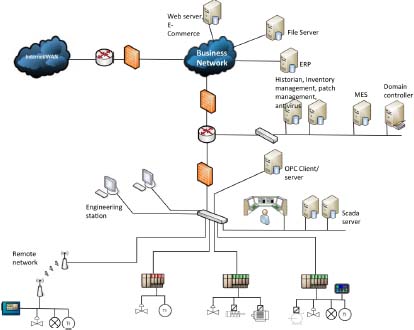
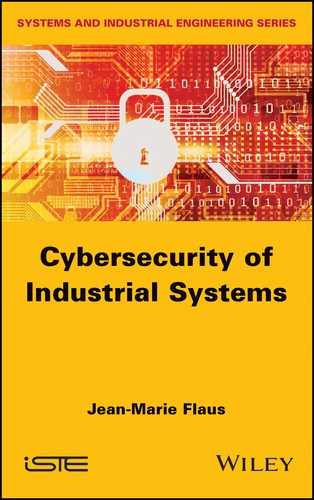
Figure 2.1. Typical ICS architecture. For a color version of this figure, see www.iste.co.uk/flaus/cybersecurity.zip
2.1.1. Purdue model and CIM model
The typical architecture (Figure 2.1) of an industrial control system includes several types of networks. We can distinguish between
- – the field network that connects sensors and actuators to programmable logic controllers (PLCs);
- – the control network that connects the PLCs and associated equipment, such as the human–machine interface (HMI) and the supervision system;
- – the production network that links the various control networks of the site and the manufacturing execution systems (MES) or historical servers;
- – the corporate network (or IT network).
A number of models have been proposed to structure this architecture and organize it hierarchically. These models simplify reality a little and introduce a level of decomposition that is not always so clear, but they are useful and serve as a basis for the breakdown into zones.

Figure 2.2. (a) Purdue and (b) ISA85 models. For a color version of this figure, see www.iste.co.uk/flaus/cybersecurity.zip
The first of these models is Purdue’s model (Williams 1994). It introduces five levels:
- – level 0 (physical process): this level corresponds to the physical systems used for production. The sensors and actuators are located at this level;
- – level 1 (local or basic control): this level includes the functions involved in the detection, observation and control of the physical process, which are performed by information processing systems such as PLCs, Remote Terminal Units (RTUs), etc. The latter read the data from the sensors, execute algorithms if necessary and store the state of the physical system. They can perform continuous control, discrete control, sequential control or batch control. The IEC 62443 model (Figure 2.3) explicitly shows the security (SIS) and protection systems in this level 1. The SIS are responsible for monitoring the process and automatically returning it to a safe state if it exceeds security limits. They also have the function of alerting the operator in the event of imminent hazardous conditions;
- – level 2 (supervision control): this level includes the functions involved in monitoring and controlling the physical process. It includes the HMIs of control and data acquisition systems (SCADA) and distributed systems (DCS). Equipment at this level is generally associated with the production area;
- – level 3 (operations management): this level includes the functions involved in flow management to achieve the desired production. These include batch management systems or MES, as well as historical databases or site-wide optimization or quality management systems. Part of the supervision system may also be at this level (Figure 2.3);
- – level 4 (enterprise business systems): this level includes the functions involved in the management of manufacturing and processing operations. Enterprise resource planning (ERP) is the main system used at this level. It manages basic production planning, raw material use, transport and stock levels. In general, the ERP provides the MES with a list of manufacturing orders that the MES will have the task of executing, controlling the flow of operations and their traceability, providing the ERP with material consumption, production performance and the quality of the manufactured products.
Purdue’s model provides a reference model for the hierarchical representation of the company’s control systems. It is easily adaptable by end users, system integrators and OEM suppliers to integrate their offerings into the enterprise levels. Such adaptation (Figure 2.4) is proposed, for example, by the alliance between Cisco and Rockwell Automation, which have integrated Purdue’s model into their Converged Ethernet or Converged Plantwide Ethernet solution architectures. Compared to the initial version, a demilitarized zone (DMZ) appears between levels 3 and 4 to separate the company’s industrial (Operation Technology [OT]) and IT networks. This architecture is often used as a basis for the implementation of a secure architecture (Chapter 10).
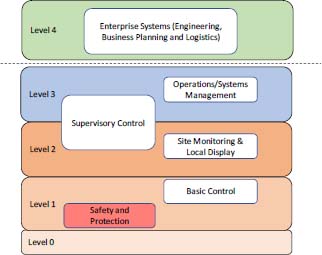
Figure 2.3. IEC 62443 model. For a color version of this figure, see www.iste.co.uk/flaus/cybersecurity.zip
Figure 2.4. Converged Plantwide Ethernet (CPwE) model. For a color version of this figure, see www.iste.co.uk/flaus/cybersecurity.zip
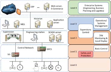
Figure 2.5. Model of the previous installation according to the CIM architecture. For a color version of this figure, see www.iste.co.uk/flaus/cybersecurity.zip
2.1.2. Architecture of the Industrial Internet of Things
The Internet of Things (IoT) is a system composed of computer devices connected to each other. Each object has a unique identification and the ability to transfer data over a network without requiring interaction between humans or between humans and machines.
In an industrial context, objects are as close as possible to the physical world and allow data to be acquired or actuators to be controlled. These elementary objects can exchange data with equipment called “aggregators” or gateways that act as relays to transfer data via the Internet to processing and storage platforms. These data and services are made available to the various users.
The objects are therefore not directly connected to the Internet, but form subnetworks that are themselves connected to the Internet. The protocol used by these subnetworks is often specific, more adapted to the IoT in terms of distance or energy needs (section 2.2) than the Transmission Control Protocol (TCP)/Internet protocol (IP) stack used by the Internet (Figure 2.9).
The tendency of Industrial Internet of Things (IIoT) is to separate low-level tasks (measurements, actions) and algorithmic aspects that are implemented on a platform accessible via the network. Most of the IIoT equipment are therefore sensors, actuators or Programmable Automation Controller (PAC).
The architecture of an IIoT system (Lin et al. 2017; Voas 2016) (Figure 2.6) is formed of three levels:
- – the level that groups objects, aggregators and distribution centers. At this level, different types of networks can be used to meet field constraints (energy consumption, distance) and to ensure communication between objects and equipment connected to the traditional IP data network, called edge devices;
- – the level corresponding to the processing and storage platform. At this level, transfers use traditional computer networks, and storage is done in the cloud on storage and data processing platforms;
- – the level corresponding to use of the data: this can be done by different components of the company, in particular by OT users for the control and maintenance of the installations.
It can be noted that the IIoT architecture is not a simple direct connection of devices to the Internet, but is carried out via a set of gateways that have more or less important data processing capabilities. These gateways also allow the various protocols used by IIoT (section 2.2) to be converted to IP.
Data processing can be carried out at several levels:
- – Cloud computing consists of processing data at the storage platform level;
- – Fog computing is processing performed on the gateways of the local network (IoT gateway). It is essentially an intermediate layer between the cloud and the hardware to allow initial processing in order to reduce the amount of data to be transported to the cloud;
- – Edge computing is carried out at the level of devices in contact with the physical system, for example, in PAC in order to guarantee a certain response time and independence from communication malfunctions.
The choice of the processing level is made depending on the necessary reactivity, the amount of data to be transmitted and whether or not the local data are sufficient to carry out the treatment.
These different levels of treatment can be illustrated in the context of an intelligent lighting system, which operates on the basis of movement. When there is motion detected, data are sent and must be processed to turn the lamps on or off. It is more appropriate to perform this processing locally (at the periphery, edge computing). Switching on or off according to brightness is more global, and it is preferable to process it at the gateway (fog computing). The company that operates the intelligent lighting system may also want to monitor the energy efficiency and lifetime of the lamps. The data that provide this overview of intelligent lighting usage are sent to the cloud to generate usage reports.
This type of infrastructure with local processing (edge or fog computing) is well suited for industrial control systems in which reflex functions can be performed locally, while more advanced processing will be performed in the cloud.
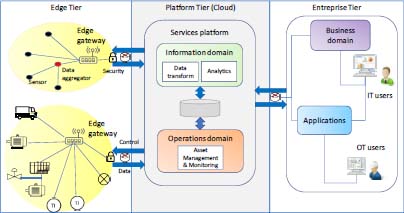
Figure 2.6. IIoT architecture. For a color version of this figure, see www.iste.co.uk/flaus/cybersecurity.zip
2.2. Different types of communication networks
2.2.1. Topology
The exchange of information between different computer equipments is done via a physical wired connection, a wireless connection or exchanges of mass memory (USB sticks, disk, etc.). In the first two cases, we speak of a computer network1.
how the workstations are connected to each other. There are different topologies: star, bus, mesh (partial or total), ring. Depending on the topology chosen, it will be easier to wire or more robust against connection failures.
The most common topology encountered for workstation networks is star topology, which requires a concentrator called a “switch”. Bus topology is found when equipment is connected from one person to another, which is the case with sensor or actuator networks. Ring topology is used for industrial networks, for which a “self-healing” function offers a certain redundancy, and mesh topology is used to obtain a better robustness.
A mixed topology presented in Figure 2.8 is found in IIoT architectures. Each IIoT device subnetwork is connected to a gateway with a star or mesh architecture, and the gateways are connected in a star configuration to a higher network or to the Internet to provide the connection to the cloud.
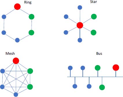
Figure 2.7. Classic network topologies. For a color version of this figure, see www.iste.co.uk/flaus/cybersecurity.zip

Figure 2.8. Mixed network topology (IIoT). For a color version of this figure, see www.iste.co.uk/flaus/cybersecurity.zip
2.2.2. Types of networks
There are different types of networks that are classified according to their scope and maximum throughput:
- – a Local Area Network (LAN) is a corporate network that is usually limited to a building, a floor or a room. In modern networks, most computers are connected to a local network via one or more switches. Several local networks can be connected via a router or a virtual private network (VPN) (section 2.2.3). A LAN can be wired or wireless and, in this case, it most often uses the Wi-Fi protocol;
- – a Personal Area Network (PAN) is a network that covers a small area, of the order of a few tens of meters, centered around a person and uses protocols such as Bluetooth classic or Bluetooth Low Energy (BLE), IEEE 802.15.4, Zigbee or ISA100.11a, which are detailed below;
- – a Low-Power Wide Area Network (LPWAN) is a network that can have a range of up to 10 km and uses protocols such as LoRaWAN or SigFox. The flow rate is limited, but it uses little energy.
We also find the following acronyms:
- – a Body Area Network (BAN) is a network of devices attached to the body, such as medical devices or gadgets;
- – a Wide Area Network (WAN) is a network extended over several countries or even worldwide, such as the Internet;
- – a Metropolitan Area Network (MAN) is a network deployed at the scale of an urban area, often consisting of several LANs.
The networks used in ICSs are essentially LAN networks, wired or wireless. PAN networks are used to connect terminal equipment such as sensors to a gateway connected to the LAN network.
In IIoT installations, there are also LPWAN-type networks, combining devices such as sensors, with low-energy resources, but requiring only a reduced data transfer rate.
2.2.3. Virtual private network
A VPN is a network that relies on an existing public infrastructure, such as the Internet, to which it adds a set of security mechanisms based on encryption and/or authentication. Almost all VPNs provide the capability to secure access to an entire network and, because of powerful cryptology, they also protect against espionage and manipulation. They work on the TCP/IP stack (Figure 2.9) on layers 3, 4 or 7. Appendix 1 provides more details on how encryption security works.
Typical protocols or protocol stacks are IPsec, PPTP and OpenVPN. Generally, they are used to connect external agencies and to integrate mobile employees. A VPN can be considered secure, but the source or destination may not be, and they may be contaminated by malicious software. As the communication is encrypted, any possible detection of suspicious exchanges is impossible. The use of a VPN does not therefore solve all problems.
2.2.4. OSI model
The Open Systems Interconnection (OSI) model is a conceptual model for standardizing the internal functions of a communication system by partitioning it into layers of abstraction. It defines seven layers:
- – physical: the physical layer ensures transmission through a physical, electrical, wired, optical or radio transmission means;
- – data link: the data link layer provides data transfer from node to node (between two directly connected nodes), and also manages the error correction of the physical layer. It manages MAC addresses (which are identifiers linked to a machine or a network interface of a machine);
- – network: this layer is responsible for the transmission of packets, including routing through different routers. It manages the logical addressing mechanism (IP address);
- – transport: the transport layer manages the coordination of data transfer between hosts using a protocol such as the Transport Control Protocol (TCP) or the Unified Datagram Protocol (UDP). It manages the retransmission in case of error;
- – session: when two devices (computers or servers) need to exchange, a session must be created in order to keep information on the status of the current transmission, and this is done at the session layer. The functions of this layer involve configuration, coordination (how long a system must wait for a response, for example) and termination;
- – presentation: the presentation layer prepares the data and, in general, ensures translation of the application format into the network format. In other words, the layer “presents” the data for the application or network. A good example of presentation is the encryption and decryption of data for secure transmission, which occurs at layer 6;
- – application: this layer provides services (http, ftp, smtp, etc.) for applications with which users interact directly.

Figure 2.9. OSI models and TCP/IP stack. For a color version of this figure, see www.iste.co.uk/flaus/cybersecurity.zip
2.3. Transport networks
2.3.1. Ethernet
Over the years, Ethernet has become the standard protocol for wired communication. It operates at level 2 and uses the MAC addresses of the various connected devices to transport the data. The IEEE 802.3 standard defines the standard version of Ethernet with the carrier sense multiple access/collision detection (CSMA/CD) protocol for sharing physical access to the network. This protocol is not real time in the sense that the time for a transmission cannot be guaranteed in a deterministic way.
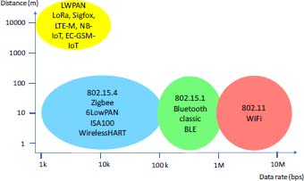
Figure 2.10. Different wireless communication solutions. For a color version of this figure, see www.iste.co.uk/flaus/cybersecurity.zip
2.3.2. Wi-Fi
Wi-Fi is a set of communication protocols defined by the IEEE 802.11 standard, allowing a wireless local area network to be built. Physical transport is provided by radio waves. Wi-Fi operates at level 2 of the OSI model, and is often coupled to the TCP/IP.
Wi-Fi makes it possible to connect computers and communicating objects or even peripherals to a broadband connection: from 11 theoretical Mbit/s or 6 real Mbit/s in 802.11b, to 54 theoretical Mbit/s or about 25 real Mbit/s in 802.11a or 802.11g, and even up to 1.3 theoretical Gbit/s for the 802.11ac standardized in 2013.
The range can reach several tens of meters indoors, if there are no obstacles.
2.3.3. The IEEE 802.15.1 (Bluetooth) standard
Bluetooth is a communication system born in the 1990s, operating in the free 2.4 GHz band and defined by the IEEE 802.15.1 standard, and is a robust solution that allows devices to be connected in master-slave mode (maximum seven slaves), over a range of a few meters to a few tens of meters, with a maximum throughput of 2.1 Mbit/s in the V2.1 version. The V3.0 version, called “high speed”, based on an 802.11 Wi-Fi layer can reach up to 24 Mbit/s. This version supports IP frames.
A low-power version called BLE has been developed for the IoT. Version 5, adopted in 2016, increases the range to 300 m, with a throughput of 2 Mbit/s.
2.3.4. IEEE 802.15.4 networks
802.15.4 is a communication protocol defined by the IEEE for connected objects. It is intended for wireless networks of the Low Rate Wireless Personal Area Network (LR WPAN) family. These are short-range, low-speed networks for low-power devices. The range is about a few tens of meters with a throughput of 250 kbit/s. It offers a solution for the lower layers that is based on the Zigbee solution.
The 802.15.4 standard is used by many implementations based on proprietary protocols or IP, such as the Zigbee protocol and several industrial solutions:
- – WirelessHart, proposed in 2007 by a consortium called Hart Communications Foundation (HCF) with more than 210 members;
- – ISA100.11a, proposed by the ISA in 2009 and approved by a committee representing 250 companies.
These solutions add mechanisms that provide better robustness, availability, and real-time performance adapted to the requirements of industrial applications. These mechanisms are mesh network and deterministic network mechanisms. The ISA100.11a standard ensures compatibility with 6LowPAN, which is a standard defining an adaptation layer between IP6 and 802.15.4 networks (see section 2.6.1).
These protocols are used as protocols for IIoT field networks between objects and concentrators.
2.3.5. LPWAN networks
The LPWAN family of networks is designed to connect devices that require little bandwidth and have low-energy resources. In this family, the most well-known solutions are the LoRa and Sigfox systems.
The range can be up to 10 km, and the flow rate is quite low. For example, it is around 100 bps for Sigfox and 0.25-50 kbps for LoRa. The devices targeted are low-energy sensor networks.
2.3.6. Cellular networks
In the meantime, a number of cellular network standards have been introduced for LPWAN networks. These are as follows:
- – the LTE-M (Long-Term Evolution) standard, also known as eMTC (Enhanced Machine Type Communication), a low-speed version that uses less energy than the LTE standard (marketed as 4G);
- – the NB-IoT standard, with a maximum throughput of 60 kbps and a positioning close to LoRa and Sigfox;
- – the EC-GSM-IoT standard, which is based on the GSM (2G) standard and supports data rates between 350 bps and 70 kpbs.
The 5G has been designed to deliver many improvements: a significant reduction in energy consumption, low latency (less than millisecond), and throughput up to 10 Gbps.

Figure 2.11. IIoT protocols and OSI model. For a color version of this figure, see www.iste.co.uk/flaus/cybersecurity.zip
2.4. Internet protocols
2.4.1. The Internet protocol
IP is one of the main protocols used by the Internet. The most widely used version is the IPv4 version. Like Ethernet, it is a stateless protocol (no session information), which means that it does not know any relationship between packets. This protocol is used to define the source and destination host on layer 3, to find the (fastest) path between two communication partners, to route packets and to handle errors with Internet Control Message Protocol (ICMP). For example, an error occurs if the destination is inaccessible.

Figure 2.12. Data packages. For a color version of this figure, see www.iste.co.uk/flaus/cybersecurity.zip
An IP frame contains information about the source, destination, technical information and the data itself (Figure 2.13). An IPv4 address is defined by four bytes (e.g. 192.168.1.1.2).
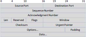
Figure 2.13. IP frame
2.4.2. Transmission Control Protocol
TCP layer provides session management. A new TCP session is initiated by a “three-way handshake”, which offers a well-known vulnerability. TCP numbers all packets to ensure that they are processed in the same order as the one transmitted by the source system. The destination host sends an acknowledgment to inform the source that the packet has been received correctly after checking a checksum, otherwise the source retransmits the packet. Finally, TCP allows the use of ports. The port of the sending instance is called a “source port” and the receiving port on the target is called a “destination port”. Commonly used application protocols such as HTTP, FTP, IRC, etc., have a default port of less than 1024. For example, an HTTP server normally listens on port 80.

Operation of a “three-way handshake” is as follows:
- – SYN: the client that wants to establish a connection with a server will send a first SYN (synchronized) packet to the server. The sequence number of this packet is a random number x;
- – SYN-ACK: the server will respond to the client using a SYN–ACK (Synchronize–Acknowledge) packet. The ACK number is equal to the sequence number of the previous packet (SYN), incremented by one (x + 1), while the sequence number of the SYN-ACK packet is a random number y;
- – ACK: finally, the client will send an ACK packet to the server, which will serve as an acknowledgment of receipt. The sequence number of this packet is defined according to the value of the acknowledgment received previously (for example: x + 1) and the ACK number is equal to the sequence number of the previous packet (SYN-ACK), incremented by one (y + 1).
A SYN flood attack works by not responding to the server with the expected ACK code. The malicious client either cannot send the expected acknowledgment of receipt or, by usurping the source IP address in the SYN, force the server to send the SYN-ACK to a fake IP address, which will therefore not send an ACK, because it has never sent a SYN. The server will wait for the acknowledgment of receipt for some time, as simple network congestion could also be the cause of the missing ACK. However, in an attack, semiopen connections created by the malicious client consume resources on the server, and can ultimately exceed the available resources and cause a server service failure.

Figure 2.15. TCP and UDP frame
2.4.3. Unified Datagram Protocol (UDP)
UDP is, like TCP, a transport layer protocol, but unlike TCP, it does not manage the notion of session and is therefore classified as stateless. In addition, it does not manage the loss of packet order and only implements the addressing of programs by ports. A typical UDP header is shown in Figure 2.15. UDP is mainly used for streaming services such as radio or Internet TV, but it is also the most widely used transport protocol for DNS. The advantage of UDP is its much higher speed than TCP.
2.4.4. Address Resolution Protocol (ARP)
Address Resolution Protocol (ARP) is used between layers 2 (Ethernet) and 3 (IP). It is used to establish the correspondence between MAC addresses and IP addresses. The opposite is done by Reverse Address Resolution Protocol (RARP). When a source host tries to communicate with a destination host for the first time, it sends a communication request to all workstations in the network, indicating the destination’s IP address. The machine that has this IP address will be the only one to respond by sending an ARP response to the sending machine containing the information < IP_address, MAC_address >. To send this response to the right computer, it creates an entry in its ARP cache (translation table) from the data contained in the ARP request it has just received. The machine that made the ARP request receives the response, updates its ARP cache and can therefore send the message that it had put on hold to the computer concerned. An attack to intercept communications is to make this table corrupt (cache poisoning).
2.4.5. Internet Control Message Protocol (ICMP)
ICMP, documented in RFC 792, is a protocol that is closely integrated with operation of the IP. ICMP messages, delivered in IP packets, are used for messages related to network malfunctions. Of course, since ICMP uses IP, the delivery of ICMP packets is not reliable, so hosts cannot rely on receiving ICMP packets for any network problems. A well-known use of ICMP is made when sending an ICMP echo request with the ping command to test if a computer is reachable and to measure network latency. Other ICMP messages contain error information (non-accessible hosts, non-accessible network portion), congestion information (router receiving too many packets, timeout, etc.), or redirection information to indicate to a host that there is a better router to reach its destination.
2.4.6. The IPv6 protocol
IPv6 is the latest version of the IP. It is an improvement of IPv4 that has been developed to address the main deficiencies of IP4, including address depletion and security. IPv4 addresses have 32 bits (4 bytes): they change to 128 bits with IPv6, which is adapted to the development of the IoT. We have about 3.4 × 1038 addresses. To better understand the size of this address space, it can be seen that each human being will be able to have at least several billions of billions of addresses. An example of an IPv6 address is as follows:
Security is enhanced with the integration of IPsec (Annex 1) into IPv6, which means that two devices can automatically create a secure tunnel without any special intervention.
In addition, the header is improved, shorter and without checksum, making routing easier.
The ARP protocol, used by IPv4 to perform MAC address and IP address matching, is replaced by Neighbor Discovery Protocol (NDP) and SEcure Neighbor Discovery (SEND). One of the vulnerabilities allowing Man In The Middle attacks (Chapter 4) disappears.
The broadcast function (broadcasting a message to all devices) is deleted.
Finally, as there are enough addresses available, an address is associated with each device, and there is no longer any need for an address translation mechanism (NAT) and a private network concept as in IPv4, with addresses defined in the range 192.168.0.0 to 192.168.255.255, for example. For security reasons, however, IPv6 has an equivalent of the private IPv4 address in the form of a unique local address that is not globally routable. This way, the device is not visible from the outside.
Both IPv4 and IPv6 versions can coexist on the same network.
2.5. Industrial protocols
2.5.1. Introduction
The equipment of an ICS exchanges information using many protocols. Some are designed for specific application areas such as control systems in the chemical or petroleum industry, construction, electrical distribution systems, or for vehicles.
In general, in an ICS, it is first necessary to transmit data between sensors and actuators and level 1 processing systems. The transmission distance can vary from a few meters to a few hundred meters; the transmission can even be carried out over a much greater distance for telemetry systems. At this level, we talk about fieldbuses, and there are, for example, Modbus, Profibus, Asi-bus or DeviceNet protocols. The transmission is often made via an RS232 or RS485 link, a radio link or a GSM link. As a reminder, it can also be carried out by an electrical signal up to the PLC input and does not use a computer protocol (Chapter 1).
At the higher level, between levels 1 and 2, it is necessary to transmit information between the processing units (PLC, RTU, etc.) and the supervision system. The protocols used at this level are often Modbus, Profinet, Ethernet/IP or OPC-UA-based exchanges (where OPC is OLE for Process Control and UA is Unified Architecture). Data transmission is carried out via Ethernet, either in its classic non-deterministic version or in a so-called real-time version. Exchanges at higher levels (above level 2) are generally based on traditional computer protocols such as Ethernet or Wi-Fi and TCP/IP.
Since the 1990s, there has been a convergence of protocols that first used Ethernet 802.3, then wherever real-time aspects are not critical, use IP, which also allows the use of Wi-Fi equipment. IP network equipment is ubiquitous, easy to deploy, relatively inexpensive and well known to administrators. This technology facilitates the connection of manufacturing systems with the company’s IT systems for better production management. It should also be noted that this convergence is not limited to ICS and business management aspects, but that voice (VoIP), television, video surveillance, and many services also use IP networks. It explains the significant increase in companies’ vulnerability to cyber-attacks.
Fieldbus protocols that do not use TCP/IP or even Ethernet, as actuator/sensor interface (AS-i) presented below, are not vulnerable to attacks from the Internet2. Similarly, networks using an Ethernet protocol but not TCP/IP (such as Profinet RT) are, to some extent, less vulnerable.
2.5.2. Modbus

Figure 2.16. Modbus and OSI communication stack
Modbus is one of the oldest industrial control protocols. It was introduced in 1979 for PC-automated communications and used a serial type communication. In the 1990s, it grew considerably and, with a view to better integration with modern systems, a version for TCP/IP networks, called Modbus/TCP, appeared in 1999. At present, it is one of the most widely used protocols in many types of industries, including critical infrastructure. Modbus is a protocol located in the application layer (Figure 2.16), thus allowing different physical means of transport to be used. There are three types of Modbus implementation:
- – Serial Modbus using RS232 or RS485 links, in RTU and ASCII version (bytes are encoded on two hexadecimal characters), using a variety of physical means of transmission (electrical cables, fiber, radio, etc.);
- – Modbus+ over HDLC (high-level data link control) using a high-speed token-passing network;
- – Modbus TCP/IP over Ethernet.
In general, the TCP/IP version is used between levels 1 and 2, that is, between PLCs and supervision, whereas the RTU version is used between levels 0 and 1 to connect PLCs and Intelligent Electronic Devices (IEDs) to PLCs. The trend is toward a generalization of TCP/IP even at the lowest levels.
The Modbus protocol is common to all implementations. It is a master– slave protocol. The master controls the communication, and the slaves respond to the requests. The protocol is very simple: there is no procedure to connect to the network, no detection of maximum response time and no diagnosis of the slave’s status. The basic functions essentially allow words to be read or written from the slave’s memory, and the frames contain a function code and associated data.
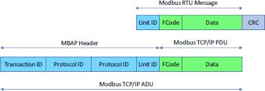
Figure 2.17. Modbus frame. For a color version of this figure, see www.iste.co.uk/flaus/cybersecurity.zip
The Modbus protocol is not secure, the frame content (Figure 2.17) is easily accessible, and they can be easily modified. In addition, since some commands can be issued in broadcast mode (sent to all receivers), a denial of service (DoS) attack can easily be performed. The vulnerability of Modbus is all the more worrying as it is used over TCP/IP.
2.5.3. Profibus and Profinet
Profibus (PROcess Field BUS) is a fieldbus communication standard promoted in 1989 by the German Ministry of Education and Research and an association of several institutions and industries including Siemens. It is based on serial communications by cable (RS-485) or optical fiber. It is a master–slave protocol like Modbus, but a little more sophisticated, with a procedure to join a network and time validations.
Profibus is a fieldbus mainly designed to connect field devices to the PLC and is not vulnerable to attacks via TCP/IP.
Profinet is a Profibus-based standard that adopts Ethernet as the physical interface for connections rather than RS485 and has a token-based repetition system to provide real-time functionality, modifying the protocol over a fraction of the time with a given periodicity, with the remainder of the period operating in conventional 802.3 Ethernet (Figure 2.18b). Profinet offers full TCP/IP functionality for data transmission, which allows applications to use it with a wireless network and high-speed transfers. The equipment using Profinet is oriented toward reliability and real-time communications. Figure 2.18a shows the architecture of Profinet.
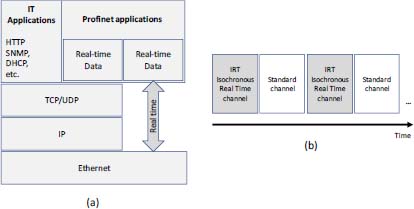
Figure 2.18. (a) Profinet architecture; (b) Ethernet time division
Profinet does not have any native security features. The functionalities incorporated in the protocol focus on improving system availability and operational reliability. To prevent potential attacks on a Profinet network, it is necessary to set up a segmentation of networks, Virtual LANs (VLAN) or introduce a DMZ (Chapter 10).
2.5.4. Actuator/sensor interface
AS-i was defined and developed by a consortium of 11 German and Swiss companies between 1990 and 1994. The objective was to provide a suitable fieldbus for connecting sensors and actuators. The system was designed on the basis of a simple unshielded two-conductor cable, capable of transferring data and a 24 V power supply. It uses a serial equipment topology and a master–slave protocol with a defined response time. On a bus, there is only one master and one power source. An AS-i message consists of a master request, a master pause, a slave response and a slave pause. By design, AS-i does not work over TCP/IP and is not one of the most vulnerable protocols.
2.5.5. Highway Addressable Remote Transducer
The Highway Addressable Remote Transducer (HART) protocol has been in existence since the late 1980s. It is a two-way communication protocol that provides data access between intelligent instruments and host systems. It is managed by HCF (HART Communication Foundation). Initially designed to operate with a 4-20 mA wired link, it has evolved to give rise to the WirelessHART protocol.
WirelessHART is a secure network technology operating in the 2.4 GHz radio band according to the IEEE 802.15.4 standard (section 2.3.4). Communication is managed between nodes using a network manager, and a security manager manages authentication. The HART protocol stack consists of four layers: physical layer, data link layer, transport layer and application layer.
Security services are offered at the data link level (level 2) and at the network level (level 3) in order to obtain a level of security equivalent to the wired solution. All messages are encrypted.
2.5.6. DNP3 and IEC 60870
DNP3 is a communication protocol developed in 1993, and widely used in the electricity sector, mainly in the United States and Canada. It is rarely used in Europe, as there are alternatives such as IEC-60870-5-101 or IEC-60870-5-104, which are different versions. It is a three-layer protocol, operating at the data link, application and transport layer levels. It was adapted in 1998 for use on an IP network with packet encapsulation with TCP and UDP.
DNP3 is a protocol designed to maximize system availability, with less emphasis on confidentiality and data integrity factors. At the data link level, some functions are included for detecting transmission errors by calculating the cyclic redundancy check . No additional security measures to the Ethernet protocol are proposed at this level. At the application level, a variant of DNP3 adds the possibility of authentication, which solves several security problems. It prevents identity theft and message modification by malicious actors.
2.5.7. The CAN bus
Controller Area Network (CAN) is a protocol that was developed by Bosch and is currently described by the ISO 11898 standard. It partially defines services for layers 1 (physical) and 2 (data link) of the OSI model.

Figure 2.19. CAN frame. For a color version of this figure, see www.iste.co.uk/flaus/cybersecurity.zip
CAN transmissions operate on the producer/consumer model. When data are transmitted by a CAN device, it concerns another device designated by an identifier field. This ID field, which must be unique on the network, also provides the priority of the message. All other CAN devices listen to the sender and only accept messages about them.
This protocol is a serial type protocol. A CAN protocol frame consists of an identification field and a data field of up to 64 bits, plus various synchronization and verification bits. It is widely used in the automotive world: most of the models currently produced use it. It is relatively unsecured and has been the subject of famous attacks, such as the Jeep hacking in 2015 (Miller and Valasek 2015).
2.5.8. Ethernet/IP and Common Industrial Protocol (CIP)

The Common Industrial Protocol (CIP) is a protocol developed by the Open Device Vendor Association (ODVA) to automate industrial processes. CIP includes a set of services and messages for control, security, synchronization, configuration, information, etc., which can be integrated into Ethernet networks and the Internet. A number of CIP adaptations, providing intercommunication and integration for different types of networks, have been proposed:
- – Ethernet/IP: an adaptation of CIP to TCP/IP;
- – ControlNet: a CIP integration on Concurrent Time Domain Multiple Access (CTDMA)3, which allows deterministic time communications for critical real-time applications;
- – CompoNet: a version adapted to time-division multiple access (TDMA) technologies;
- – DeviceNet: a CIP adaptation with a CAN controller presented above.
CIP is a protocol based on object-oriented modeling. Each object consists of attributes (data), services (commands), connections and behaviors (relationships between data and services). CIP offers a wide range of objects to cover typical communications and functions with common elements in automation processes, such as input or output devices, whether analog or digital, HMIs, motion controls, etc. The notion of profile makes it possible to define if a common communication object is implemented in a piece of equipment. The communication is based on the producer–consumer model, which can be single or multicast. In the first case, we are talking about explicit messages and in the second case, implicit messages.
Although CIP uses a formalized model, it does not define any mechanism, implicit or explicit, for security. In addition, it defines objects required to identify devices, which can facilitate the discovery of equipment in the network and provide targets for attackers. Since there are also common application objects for exchanging information between devices, an intruder is able to manipulate a wide range of industrial devices using this type of object. In addition, the characteristics of some CIP messages (real-time, multicast) are incompatible with communication encryption, so CIP does not provide mechanisms to do this.
Ethernet/IP (IP stands for Industrial Protocol) is a standard developed in the 1990s. EtherNet/IP is a CIP encapsulation for Ethernet networks. Commands, data and messages are provided in CIP frames.
As a CIP protocol, Ethernet/IP defines two connection methods for its TCP/IP communications. These are explicit messages, using the TCP, and implicit messages using the UDP. Explicit messages follow the client–server or request–response connection model. Among them are messages between PLCs and HMIs, diagnostic messages and file transfers. The commonly used ports are TCP port 44818 and UDP port 2222.
Although Ethernet/IP is more modern than protocols like Modbus, it still has security issues that leave it vulnerable.
2.5.9. OLE for Process Control (OPC)

OPC is not an industrial communication protocol, but rather an operational solution using object linking and embedding (OLE) for communications in Windows-based industrial control systems. OPC provides communication capabilities for ICSs using Windows workstations.
OPC was originally based on DCOM (Distributed Component Object Model) and many OPC systems still use it, although there is an updated version called OPC-UA (Mahnke et al. 2009), which allows the use of SOAP over HTTPS and is much more secure. This version has many open-source4 implementations and can be used on different operating systems.
The use of DCOM and RPC (Remote Process Call) makes OPC very vulnerable to attacks and, as OPC is based on OLE, it can also be affected by all its vulnerabilities. In addition, since OPC is running on Windows, it can also be affected by all operating system vulnerabilities. As it is quite difficult to apply patches to industrial control systems, many vulnerabilities already discovered and for which patches are available continue to be exploitable on some industrial control networks.
OPC-UA has a security model (Armstrong and Hunkar 2010) that provides greater security to the architecture, so it is advisable to deploy OPC-UA rather than the traditional version of OPC.
2.5.10. Other protocols
There are many other protocols such as Powerlink Ethernet (another realtime version of Ethernet), EtherCAT (Ethernet for Control Automation Technology) and KNX (specialized for building). Details on these protocols can be found in Zurawski (2014).
2.6. IoT protocols
A number of protocols have been developed for the IoT. A first protocol, called 6LowPAN, is located between the network layer and the link layer of the OSI model, while others are at application level, such as Message Queuing Telemetry Transport (MQTT) and Constrained Application Protocol (CoAP), and are located at level 7 of the OSI model (Figure 2.11).
2.6.1. 6LowPAN
6LoWPAN, created by a group from the Internet Engineering Task Force (IETF), is an acronym formed from IP6 and low-power wireless personal area networks (LoWPAN). Its objective is to allow devices with limited processing capacity to transmit information wirelessly using Internet protocol. It is a competitor of Zigbee. It allows 802.15.4 devices to communicate using IP6. The main features of 6LoWPAN are as follows:
- – packet fragmentation and reassembly, as 802.15.4 frames have only 81 bytes;
- – IP6 header compression;
- – the routing of fragments in the local network;
- – functions for data security.
Examples of applications are smart meters. In addition, 6LoWPAN is very promising in home automation applications such as lighting or thermostats.
2.6.2. Message Queuing Telemetry Transport
MQTT is a publication/subscription messaging protocol for Internet devices on low-resource objects and low-bandwidth, high-latency or unreliable networks. Given its characteristics, it is an ideal protocol for machine-to-machine (M2M) communication.
MQTT was developed in 1999, but with the exponential growth of the IoT, and the need to connect and communicate low-powered intelligent devices, MQTT has recently found a market. MQTT was designed to be a low overload protocol, which took into account bandwidth and processor limitations.
MQTT is a publish/subscribe protocol. It allows customers to connect as a publisher, subscriber or both. Communication is ensured via a broker who manages all transmitted messages. This model allows customers to communicate in one-to-one, one-to-many or multiple-to-one mode.
Each message has an address, called a “topic”. For example, the name of a topic can be temperature. Namespaces are structured in a tree structure such as:
plant1/compressor/valve1/temperature
Wildcards are allowed when registering a subscription (but not when publishing), which allows entire hierarchies to be observed by customers. For example:
plant1/compressor/+
allows you to subscribe to all compressor messages.
The operation is as follows: when the temperature value is changed in the “valve1” object, it issues a message to the broker. All subscribers receive a message with the new value.
2.6.3. CoAP
CoAP is the IETF CoRE group protocol (Constrained Resource Environments) for low-resource systems and can be seen as a light version of the HTTP protocol.
Like the latter, CoAP is a document transfer protocol. CoAP packets are much smaller than HTTP streams. Encoding is done to save space. Packages are simple to generate and can be analyzed without consuming a lot of memory. CoAP works on UDP, not TCP. Clients and servers communicate via stateless datagrams, and CoAP allows UDP broadcasting and multicast broadcasting. CoAP follows a client/server model. Clients make requests to servers, and servers send responses. Customers can read, modify, create and delete resources.
CoAP is designed to interoperate with HTTP and the RESTful Web in general because of simple proxies. As CoAP is based on UDP datagrams, it can be used over SMS and other packet communication protocols.
2.6.4. Other protocols
Advanced Message Queuing Protocol can be seen as an advanced version of MQTT, but it is less widely available. It has been developed by the banking world to ensure secure transactions between servers; it is adapted for IoT, in particular to meet the requirements of critical applications.
DDS is a Data Distribution Service for real-time systems defined as standard by the Object Management Group. It is suitable for M2M exchanges and allows real-time data exchanges that are reliable, efficient and interoperable. It works in publish/subscribe mode. DDS meets the needs of applications such as financial trading, air traffic control, smart grid management and other Big Data applications.
XMPP, Extensible Messaging and Presence Protocol, are a set of open client/server protocols for IETF instant messaging. It is used by Apple, Cisco, Microsoft and many industry players. It can be used as part of an IoT architecture between a platform and HMI.