13
Obstacle Avoidance Simulation and Real-Time Lane Detection for AI-Based Self-Driving Car
B. Eshwar*, Harshaditya Sheoran, Shivansh Pathak and Meena Rao
Department of ECE, Maharaja Surajmal Institute of Technology, Janakpuri, New Delhi, India
Abstract
This chapter aims at developing an efficient car module that makes the car drive autonomously from one point to another avoiding objects in its pathway through use of Artificial Intelligence. Further, the authors make use of visual cues to detect lanes and prevents vehicle from driving off road/moving into other lanes. The paper is a combination of two simulations; first, the self-driving car simulation and second, real-time lane detection. In this work, Kivy package present in Anaconda navigator is used for simulations. Hough transformation method is used for lane detection in “restricted search area.”
Keywords: Self-driving car, artificial intelligence, real-time lane detection, obstacle avoidance
13.1 Introduction
A self-driving car is designed to move on its own with no or minimal human intervention. It is also called autonomous or driverless car many times in literature [1]. The automotive industry is rapidly evolving and with it the concept of self-driving cars is also evolving very fast. Several companies are focused on developing their own self. Even the tech giants, which are not into “mainstream automobile,” like Google and Uber, seem greatly interested in it. This is due to the ease of driving opportunity that self-driving cars provide. The self-driven cars that make use of artificial intelligence to detect the obstacles around and run in an auto pilot mode are a major area of research and study these days [2]. The self-driving cars allow the users to reach their destination in a hassle free manner giving complete freedom to undertake any other task during the time of travel. Moreover, human involvement is also least, and hence, the chance of human error leading to accidents also minimizes in self-driving cars. In driverless cars, people sitting in the car would be free of any stress involved in driving and on road traffic. However, to make the self-driving cars a common phenomenon, various features have to be developed, and the system should be developed in such a way that the driverless car is able to navigate smoothly in the traffic, follow lanes and avoid obstacles. Researchers have worked across different techniques and technologies to develop the system [3]. An autonomous platform for cars, using the softmax function, is presented, which gives out the outputs of each unit between 0 and 1. The system only uses a single camera [4]. Further research was carried out in real-time in order to find the positions on the roadway by Miao et al. Canny edge extraction was administered so as to obtain a map for the matching technique and then to select possible edge points [5]. In literature, an autonomous RC car was also proposed and built making use of artificial neural network (ANN). Fayjie et al. in their work have implemented autonomous driving using the technique of reinforcement-learning based approach. Here, the sensors used are “lidar” that detects objects from a long distance [6]. The simulator used gimmicks real-life roads/traffic. Shah et al. used deep neural to detect objects. Prior to their work, “conventional deep convolution neural network” was used for object detection. Yoo et al. had proposed a method that creates a new gray image from a colored image formulated on linear discriminant analysis [7]. Hillel et al. elaborated and tried to tackle various problems that are generally faced while detecting lane like image clarity, poor visibility, lane and road appearance diversity [8]. They made use of LIDAR, GPS, RADAR, and other modalities to provide data to their model. Further using obstacle detection, road and lane detection was done and details were fed to the vehicle to follow in real-time. In the work by Gopalan et al., the authors discuss the most popular and common method to detect the boundaries of roads and lanes using vision system [9]. General method to find out different types of obstacles on the road is inverse perspective mapping (IPM). It proposes simple experiment that is extremely effective in both lane detection and object detection and tracking in video [10]. Clustering technique has also been used to group the detected points [11]. Results were found to be effective in terms of detection and tracking of multiple vehicles at one time irrespective of the distance involved.
The authors of this chapter were motivated by the work done by earlier researchers in the domain of self-driving. The objective of this work presented in the chapter is to develop a model of a car that detects lane and also avoid obstacles. Lane detection is a crucial component of self-driving cars. It is one among the foremost and critical research area for understanding the concept of self-driving. Using lane detection techniques, lane positions can be obtained. Moreover, the vehicle will be directed to automatically go into low-risk zones. Crucially, the risk of running into other lanes will be less and probability of getting off the road will also decrease. The purpose of the proposed work is to create a self-driving car model that could sustain in traffic and also avoids accidents.
13.1.1 Environment Overview
13.1.1.1 Simulation Overview
The self-driving car application uses Kivy packages provided in anaconda navigator. The aim is to allow for speedy as well as easy interactive design along with rapid prototyping. Also, the code should be reusable and implementable. The application environment in which the car “insect” will appear is made using the Kivy packages. The environment will have the coordinates from 0,0 at the top left to 20,20 at bottom right and the car “insect” will be made to traverse from the bottom right to the top left i.e. these will be the source and destination.
The idea/motive of creating this is that the car learns not only to traverse from source to destination but at the same time avoids the obstacles. These obstacles should be such that the user/developer should be able to draw and redraw the pathway for the agent as and when the agent learns the given pathway to destination and back to source. Also, the pathways, thus, created must also provide the punishment to the agent if the agent hits it. With rewards and punishments is how the agent learns. Alongside this very approach to provide punishment of to the agent as it touched the pathway or the obstacle, the degree of the punishment should vary depending upon the thickness of the pathway. Hence, the tracks that could be drawn was made such that holding the mouse pointer for longer period of time increased the thickness. The greater the thickness, the more the punishment.
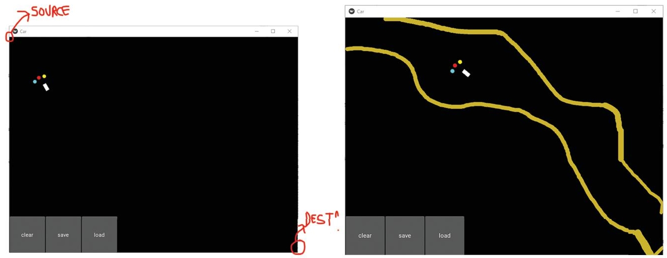
Figure 13.1 Self-driving car UI.
Since the simulation requires a need to draw and redraw the pathways as and when the agent learns the path, there is a “clear” button that clears the tracks that were created till then refer Figure 13.1.
13.1.1.2 Agent Overview
The agent created is designed to have three sensors. The sensors are placed one right at the front center, the rest two at 20 degrees to the left and right of the center sensor, respectively. These sensors can sense any obstacle which falls under the + −10 degree sector from the center of axis of the particular sensor. This is an added rectangular body just for representation, it has no functionality as such. The rectangular body gives the coordinate where the agent exists. The body moves forward, moves right left at 10-degree angle.
The sensors when finds no obstacle in front of them, it updates the information and moves in a random direction as it is exploring. Depending on the reward or the punishment that it receives upon the action that it took, it learns and takes a new action. Once the car “agent” reaches the goal it earns a reward of +2. Punishment value is decreased for going further away from the goal since avoiding the sand sometimes requires agent to move away from the destination.
Cumulative reward is introduced, instead of giving it a certain value, independent conditions sum up their rewards (which mostly are penalties). Hitting the sand earns the agent a negative reward of −3. Penalty for turning is also introduced. The model should keep its direction in more conservative way. Replacement of integral rewarding system with a binary reward for closing to the target with continuous differential value. This lets the brain keep direction, this reward is really low, yet still a clue for taking proper action for the brain.
13.1.1.3 Brain Overview
This application also uses NumPy and Pytorch packages for deep learning and establishment of neural networks that define what actions are to be taken depending upon the probability distribution of reward or punishment received. Numpy is a library that supports massive, multidimensional arrays and matrices, as well as a large number of complicated mathematical functions to manipulate them. PyTorch contains machine learning library, which is open source, and it is used for multiple applications.
13.1.2 Algorithm Used
The agent designed uses Markov decision process and implements deep q-learning and a neural network along with a living penalty added so that the agent does not only keep moving in the same position but also reaches the destination.
13.1.2.1 Markovs Decision Process (MDP)
Markovs decision process (MDP), derived from bellman equation, offers solutions with finite state and action spaces. This is done by techniques like dynamic programming [12]. To calculate optimal policies value, which contains real values, and policy, which contains actions, are stored in two arrays indexed by state. We will acquire the solution as well as the discounted sum of the rewards that will be won (on average) by pursuing that solution from state at the end of the algorithm. The entire process can be explained as updating the value and a policy update, which are repeated in some order for all the states until no further changes happen [13]. Both recursively update a replacement of the optimal policy and state value using an older estimation of these values.
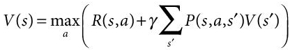 (13.1)
V(s) is the value or reward received by the agent for taking an action “a” in state “s.”
Here, the order is based on the type of the algorithm. It can be done for all states at one time or one by one for each state. To arrive at the correct solution, it is to be ensured that no state is permanently excluded from either of the steps.
13.1.2.2 Adding a Living Penalty
The agent resorts to keep bumping at the corner walls near the state where there is −1 reward. It learns that by keep bumping on the wall it will not receive a punishment but due to it being a MDP it does not know yet that +2 reward is waiting if it makes to the destination. Living penalty is a punishment or negative reward given to the agent and after appropriate simulations so that the penalty is not high enough to force the agent to directly fall into the wall since the reward is too low for it to keep trying to find the right action. At the same time, punishment should not be small enough to let the agent remain in same position. Q-learning is a “model-free reinforcement learning algorithm.” It basically defines or suggest what action to be taken under different situations [14].
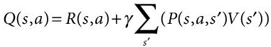 (13.2)
Q (s, a) is the quality of taking the action a at the state s after calculating the cumulative value or reward on being on next state sʹ. This is derived from MDP.
13.1.2.3 Implementing a Neural Network
When designing the agent environment to the agent is described in terms of coordinates, i.e., vectors and supplying the coordinates to the neural network to get appropriate Q values [15]. The neural network (NN) will return 4 Q values (up, down, left, right). These will be the target Q values that the model has predicted before agent performs any action and are stored.
Now when the agent actually performs the actions randomly and gets Q value, it is compared with the targeted values and the difference is called temporal difference (TD). TD is generally intended to be 0 or close to 0 i.e. the agent is doing what is predicted or learnt. Hence, the loss is fed as the input to the NN to improve the learning.
13.2 Simulations and Results
13.2.1 Self-Driving Car Simulation
Creation of more challenging path design was done that will better train the agent to traverse difficult paths and still reach the destination. The more maze-like pathways better the agent learns, hence research on the pathways that generally are used to train such models was explored. The designs that were worked upon had also to be accurate in real world otherwise it becomes more like a game than real world application worthy. Improvization in independent cars are ongoing and the software within the car is continuously being updated. Though the development started with the module of driver free cars, it has now progressed to utilizing radiofrequency, cameras, sensors, more semiautonomous feature and in turn reducing the congestion, increasing safety with faster reactions, and fewer errors. Despite all of its obvious advantages, autonomous car technology must also overcome a slew of social hurdles. Authors have tried to simulate the self-driven car for various difficult tracks and different situations Figure 13.2 shows a simple maze track with no loops involved. On the other hand, Figure 13.3 shows simulation in a hair pin bend and shows a more difficult path with multiple loops. Figure 13.4 for more difficult path to cope with looping paths.

Figure 13.2 Simple Maze with no to-fro loops involved.

Figure 13.3 Teaching hair-pin bends.
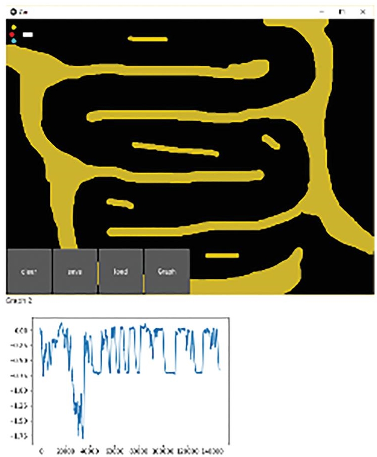
Figure 13.4 A more difficult path to cope with looping paths.
13.2.2 Real-Time Lane Detection and Obstacle Avoidance
A lane is designated to be used by a series of vehicles, to regulate and guide drivers and minimize traffic conflicts. The lane detection technique uses the OpenCV, image thresholding and Hough transform. It is a solid line or a much rugged/dotted line that identifies the positioning relationship between the lane and the car. Lane detection is a critical aspect of the driver free cars. An enhanced Hough transform is used to enable straight-track lane detection, whereas the tracking technique is investigated for curved section detection [16]. Lane detection module makes use of the frames that are provided to it by breaking any video of a terrain/road taken into frames and detects lanes. This entire process is explained through the flowchart shown in Figure 13.5. The lanes are detected, and marking is made on those frames. These frames are then stitched together again to make an mp4 video output, which is the desired result.
13.2.3 About the Model
This module makes use of OpenCV [17]. The library is used mainly for “image processing,” “capturing video” and its analysis including structures like face/object detection. Figure 13.6 depicts a lane and Figure 13.7 depicts the lane detection from video clips.
Each number represents the pixel intensity at a specific site. Figure 13.8 provides the pixel values for a grayscale image with a single value for the intensity of the black color at that point in each pixel. The color images will have various values for one pixel. These values characterize the intensity of respective channels—red, green, and blue channels for RGB images.

Figure 13.5 Plan of attack to achieve the desired goal.
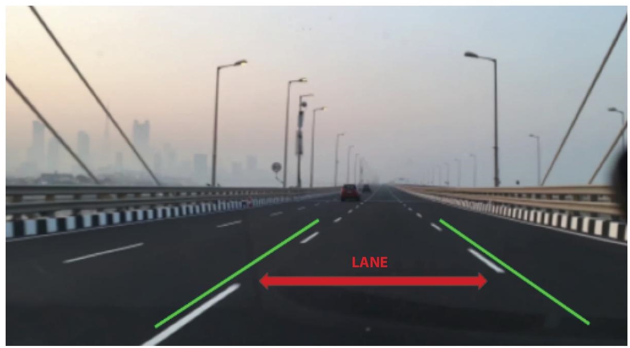
Figure 13.6 Lane.
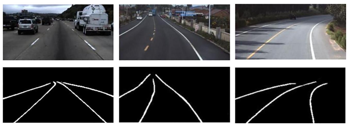
Figure 13.7 Lane detection from video clips.
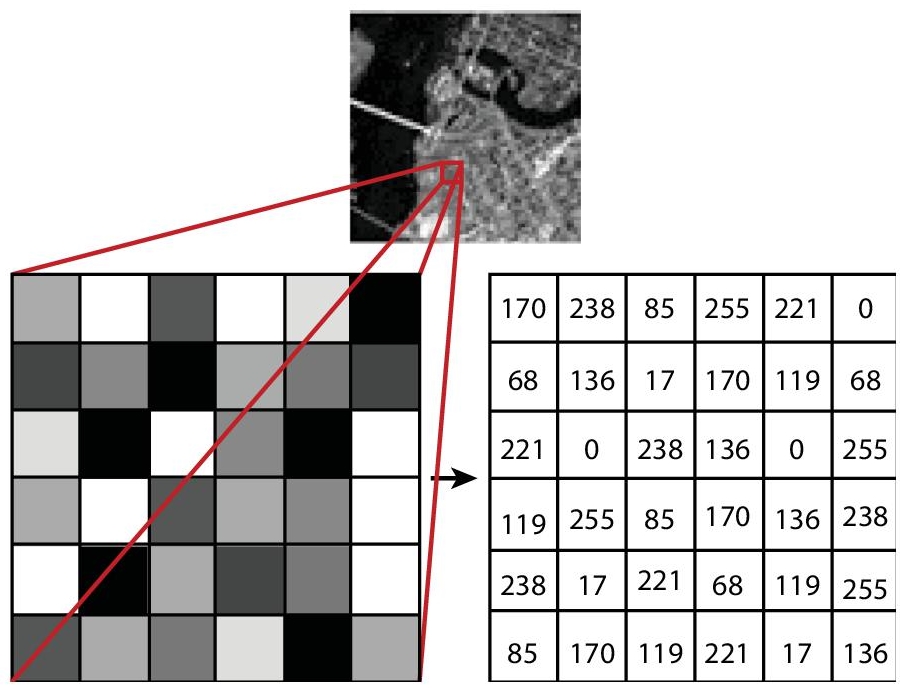
Figure 13.8 Depiction of pixel value.

Figure 13.9 Setting area of interest on the frame.
In a general video of a car traversing on a road, there are various things in any scenario apart from the traditional lane markings. There are automobiles on the road, road-side barriers, street-lights, etc. In a video, scenes changes at every frame and this reflects actual driving situations pretty well. Prior to resolving the lane detection issue, ignoring/removal of the unwanted objects from the driving scene is done [18]. The authors have narrowed down the area of interest to lane detection. So, instead of working with the entire frame, only a part of the frame will be worked upon. In the image below, apart from the lane markings (already on the road), everything else like cars, people, boards, signals etc. has been hidden in the frame. As the vehicle moves, the lane markings would most likely fall in this area only. Figure 13.9 shows how area of interest is set on the frame.
13.2.4 Preprocessing the Image/Frame
First, the image/frame is processed by masking it. NumPy array acts as a frame mask. The technique of applying mask to an image is that, pixel values of the desired image is simply changed to 0 or 255 or any other number [19]. Second, thresholding is applied on the frame. Here, provides the pixel values for a grayscale image with a single value for the intensity of the black color at that point in each pixel. The pixel can be assigned any one of the two values depending on whether the value of the pixel is greater than or lower than the threshold value. Figures 13.10 (a) and (b) show a masked image and image after thresholding respectively.
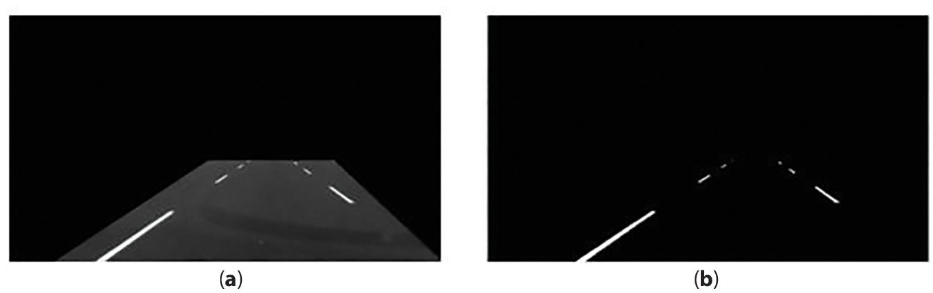
Figure 13.10 (a) Masked image (b) Image after thresholding.
When threshold is applied on the masked image, there is only lane markings in the output image. Detecting these lane markings are done with the help of “Hough Line Transformation” [20]. In this work, the objective is to detect lane markings that can be represented as lines. Finally, the above process performed on a single frame from a video is repeated on each frame and each frame is then compiled in the form of a video. This gives the final output in a Mp4 video format.
13.3 Conclusion
The images in Figure 13.11 show the detection of lanes on various video frames. By detecting lanes, the self-driving car will follow a proper route and also avoid any obstacle.
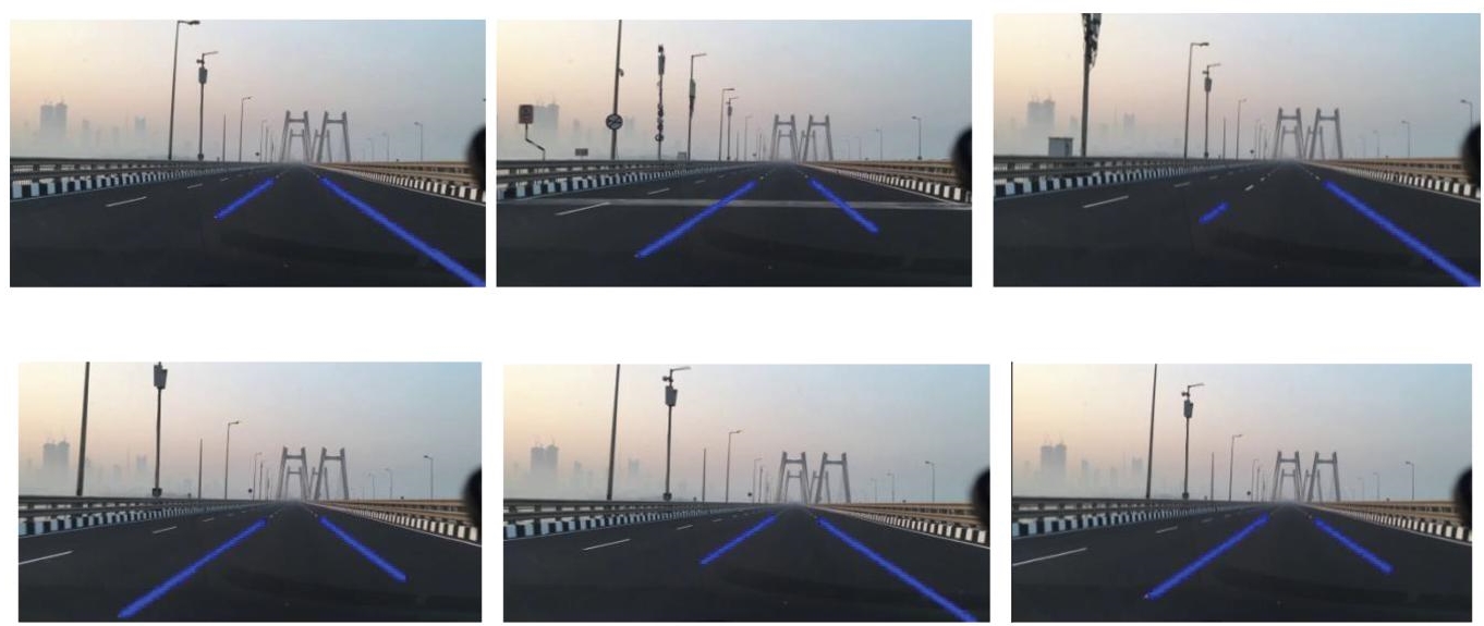
Figure 13.11 Shows lane detection in various frames of the video.
In this work, a “real-time lane detection algorithm based on video sequence” taken from a vehicle driving on highway was proposed. The proposed model uses a series of images/frames snapped out of the video. Hough transformation was used for detection of lanes with restricted search area. The authors were also able to demonstrate the simulation of a self-driving car on easy as well as difficult mazes and tracks. Subsequently, the lanes were also detected on various frames. The lane detection helps the self-driving car to move on the track while avoid any obstacles. In this way, self-driving through tack along with lane detection and obstacle avoidance was achieved.
References
- 1. By: IBM Cloud Education, What is Artificial Intelligence (AI)? IBM. Available: https://www.ibm.com/cloud/learn/what-is-artificial-intelligence.
- 2. de Ponteves, H., Eremenko, K., Team, S.D.S., Support, S.D.S., Anicin, L., Artificial Intelligence A-Z™: Learn how to build an AI. Udemy. Available: https://www.udemy.com/course/artificial-intelligence-az/.
- 3. Seif, G., Your guide to AI for self-driving cars in 2020. Medium, 19-Dec-2019. Available: https://towardsdatascience.com/your-guide-to-ai-for-self-driving-cars-in-2020-218289719619.
- 4. Omrane, H., Masmoudi, M.S., Masmoudi, M., Neural controller of autonomous driving mobile robot by an embedded camera. 2018 4th International Conference on Advanced Technologies for Signal and Image Processing (ATSIP), 2018, doi: 10.1109/atsip.2018.8364445.
- 5. Miao, X., Li, S., Shen, H., On-board lane detection system for intelligent vehicle based on monocular vision. Int. J. Smart Sens. Intell. Syst., 5, 4, 957–972, 2012, doi: 10.21307/ijssis-2017-517.
- 6. Shah, M. and Kapdi, R., Object detection using deep neural networks. 2017 International Conference on Intelligent Computing and Control Systems (ICICCS), 2017, doi: 10.1109/iccons.2017.8250570.
- 7. Yoo, H., Yang, U., Sohn, K., Gradient-enhancing conversion for illumination-robust lane detection. IEEE Trans. Intell. Transport. Syst., 14, 3, 1083– 1094, 2013, doi: 10.1109/tits.2013.2252427.
- 8. Hillel, A.B., Lerner, R., Levi, D., Raz, G., Recent progress in road and lane detection: A survey. Mach. Vis. Appl., 25, 3, 727–745, 2012, doi: 10.1007/ s00138-011-0404-2.
- 9. Gopalan, R., Hong, T., Shneier, M., Chellappa, R., A learning approach towards detection and tracking of lane markings. IEEE Trans. Intell. Transport. Syst., 13, 3, 1088–1098, 2012, doi: 10.1109/tits.2012.2184756.
- 10. Paula, M.B.D. and Jung, C.R., Real-time detection and Ccassification of road lane markings[C]. Xxvi Conference on Graphics Patterns and Images, pp. 83–90, 2013.
- 11. Kaur, G., Kumar, D., Kaur, G. et al., Lane detection techniques: A Review[J]. Int. J. Comput. Appl., 4–6, 112.
- 12. Stekolshchik, R., How does the Bellman equation work in Deep RL? Medium, 16-Feb-2020. Available: https://towardsdatascience.com/how-the-bellman-equation-works-in-deep-reinforcement-learning-5301fe41b25a.
- 13. Singh, A., Introduction to reinforcement learning: Markov-decision process. Medium, 23-Aug-2020. Available: https://towardsdatascience.com/introduction-to-reinforcement-learning-markov-decision-process-44c533ebf8da.
- 14. Violante, Simple reinforcement learning: Q-learning. Medium, 01-Jul-2019. Available: https://towardsdatascience.com/simple-reinforcement-learning-q-learning-fcddc4b6fe56.
- 15. Do, T., Duong, M., Dang, Q., Le, M., Real-time self-driving car navigation using deep neural network. 2018 4th International Conference on Green Technology and Sustainable Development (GTSD), 2018, doi: 10.1109/ gtsd.2018.8595590.
- 16. Qiu, D., Weng, M., Yang, H., Yu, W., Liu, K., Research on lane line detection method based on improved hough transform. Control And Decision Conference (CCDC) 2019 Chinese, pp. 5686–5690, 2019.
- 17. About, OpenCV, in: OpenCV, 04-Nov-2020, Available: https://opencv.org/about/.
- 18. Guidolini, R. et al., Removing movable objects from grid maps of self-driving cars using deep neural networks. 2019 International Joint Conference on Neural Networks (IJCNN), 2019, doi: 10.1109/ijcnn.2019.8851779.
- 19. Image Masking with OpenCV. PyImageSearch, 17-Apr-2021. Available: https://www.pyimagesearch.com/2021/01/19/image-masking-with-opencv/.
- 20. Hough Line Transform. OpenCV. Available: https://docs.opencv.org/3.4/d9/db0/tutorial_hough_lines.html. [12/11/2021].
Note
- *Corresponding author: [email protected]