CHAPTER 13
Working with Log Images
If you have read the previous chapter, “Log versus Linear,” you will find many of the key concepts developed there in action here. In that chapter we found the virtues of log data to be that it retains the full dynamic range of the film and is the most efficient lossless encoding of the picture information. We also learned that log images are harder to work with. In this chapter we will find out why, and what to do about it.
The issues are divided into two sections. The first is on converting Cineon log film scans to linear for working in a linear compositing environment, which most studios do. The second section addresses the issues of how to perform acts of compositing, color correction, and screen operations with log images. There are also procedures on how to incorporate linear images such as matte paintings and cgi into log composites. For artists already using Cineon software to do log compositing, the explanations and procedures will mostly explain why Cineon works the way it does. For those who would work in log space without using Cineon software, step-by-step procedures are offered on how it is done.
13.1 Converting Cineon Log Images
If you are working in linear space but have film scanned at a Cineon service bureau, the Cineon log images have to be converted to linear before you can work with them. If you have composited a shot in linear space and are going to film it out on a Cineon laser film recorder, your linear images are going to be converted to log first. How these conversions work and how to get the most out of them is the subject of this section.
When converting images back and forth between linear and log there are three conversion parameters that need to be set correctly to avoid distorting the results. The three parameters are the white reference, the black reference, and the display gamma. This section describes what each of these parameters is and how they affect the conversion in both directions.
When film is scanned to the Cineon 10-bit log format the entire 1000:1 dynamic range of the film is captured. Figure 13-1 illustrates how the picture information is distributed in the log image. The superwhites are the picture content that is brighter than regular reflective surfaces. This would include things such as specular highlights, light bulbs, and the sun. Overexposed film might start creeping up into this region. The normal exposure is that portion of the picture content that contains the “normal” picture information from properly exposed diffuse reflective surfaces such as people, cars, and buildings. Here are the key points of reference that are important to the discussion of converting images from log to linear or linear to log:
Figure 13-1: Image Distribution in Log Space
White Reference: This is where a 90 percent reflective white card should be on the negative, and will have a Cineon code value of 685 for normally exposed film.
Black Reference: This is just below the toe of the film and represents completely un-exposed film. Its code value is 95 to leave some “footroom” for the film grain to chatter up and down.
Figure 13-2 illustrates the startling results of converting the full dynamic range of a Cineon 10-bit log image to a 16-bit linear image. The normal exposure region suddenly collapses down to less than 10 percent of the full data range and the super-whites region expands to fill over 90 percent of the data space! These extreme proportions are due to the fact that the brightness difference between a pair of slacks and the sun is literally thousands of times, and the film negative is able to capture that full range.
Unfortunately, in the linear version most of the data space is wasted on this huge superwhite range, which is only sporadically used. This is one of the three reasons log data was developed in the first place. To find out the other two reasons, see Chapter 12, “Log versus Linear.” In the log version the normal exposure region expands to fill 2/3 of the data space, and the superwhites take up only 1/3. This is a much better distribution of the data to the picture information.
Now, let's imagine that this full range 16-bit linear image were displayed on your monitor. What might it look like? Since the frame buffer of your monitor is only 8 bits per channel, the maximum code value of 65,535 becomes mapped to 255, but the normal exposure code values ranging between 0 and 4849 are mapped between 0 and 19! All of the normally exposed picture information has gone to nearly black. Don't think that converting the 16-bit image to 8 bits had anything to do with this collapse to black. Changing the bit depth did not change the dynamic range of the picture, just the number of data steps between the minimum and the maximum code values. If you had a 16-bit frame buffer the image would look exactly the same.
Figure 13-2: Comparison of Log versus Linear Data
You can now see why the superwhites above the white reference are clipped out and only the normal exposure range is retained when log images are converted to linear. Linear display devices such as monitors simply lack the appropriate response curves and dynamic range to show the entire range of a film negative. Some-thing's gotta give, and that is the superwhites.
13.1.1 Log to Linear Conversions
Log to linear conversions are unique in the image format conversion world in that major portions of the log image are sacrificed (lost) when the linear version is clipped at the white reference, and, if you are not careful, the brightness and contrast of the linear version will also be inadvertently affected. Other conversions, such as targa to tiff, simply reformat the computer data between the two file formats but keep the same picture. With log to linear conversions you don't get to keep the same picture. Studios that convert their Cineon 10-bit log scans to 8- or 16-bit linear for compositing are in fact working with a surprisingly limited version of the picture. All of the conversion examples in Table 13-1 use 8 bits.
13.1.1.1 The Conversion Parameters
When a log image is converted to linear, two things happen. The first is that the normal exposure portion of the log data between the white reference and the black reference is the only portion retained in the linear version (see Figure 13-3). The second thing is that the display gamma of the resulting linear version is set. The display gamma determines the overall gamma of the resulting linear version. The default conversion settings are based on the assumption of properly exposed film. The default settings for the three conversion parameters are summarized in Table 13-1.
Here is a very important point about lin/log conversions: If a log image is converted to linear and then back to log using exactly the same conversion settings both ways, the converted log image will be identical in appearance to the original log image, with two exceptions. The converted log image will not have any data values above the white reference because they were clipped out when it was converted to linear. The other exception is if the linear version is 8 bits instead of 16 there will be scattered “data holes” in the darks of the converted log image. This is because the 256 code values of the 8-bit linear version were mapped back to (685 – 95 = ) 590 code values of the converted log version and there were not enough code values to go around. Due to the nonlinear nature of the linear to log mapping, most of the missing data points become clustered in the darks.
13.1.1.1.1 The White Reference
The white reference is the maximum log code value preserved in the linear version, and will be mapped to the maximum linear value of 255. All log picture information above this value is clipped out. If the white reference is increased to 750, for example, then more of the highlights are retained in the linear version. However, a greater dynamic range of the log image is being transferred to the fixed dynamic range of the display monitor, so the midtones are shifted down and become darker.
Figure 13-3: Log to Linear Conversion
| Table 13-1: Default Log to Linear Conversion Settings | |
| White reference | 685 |
| Black reference | 95 |
| Display gamma | 1.7 |
13.1.1.1.2 The Black Reference
The black reference is the minimum log code value preserved in the linear version, and will be mapped to the minimum linear value of 0. All log picture information below this value is clipped out. If the black reference is increased to 150, for example, then more of the blacks are clipped out in the linear version. As more of the blacks are clipped out, the midtones are pulled down and become darker in the log version.
13.1.1.1.3 Display Gamma
The display gamma setting determines the gamma of the resulting linear image and is designed in such a way that if you enter the gamma correction you use on your workstation monitor it will convert the log film data to look about right on your monitor. For example, if you set your monitor gamma correction to 1.7, you would enter a display gamma value of 1.7 during the conversion. If your monitor gamma correction is 1.0, you would enter that.
Keep in mind that this display gamma parameter is intended to be the gamma correction that you apply to your monitor, not the end-to-end gamma. It is based on the assumption that all monitors have a hardware gamma of around 2.5, so a gamma correction of 1.7 will result in an end-to-end gamma of about 1.5, the correct gamma for film. Some systems such as Macintosh and PCs may not indicate the gamma correction itself, just the end-to-end gamma. This, of course, is the wrong number to use for the display gamma setting. When in doubt, make a gamma patch and measure the end-to-end gamma as described in Chapter 9. Once you have found the end-to-end gamma you can easily calculate the gamma correction that is being used.
13.1.1.2 Customizing the Conversion Parameters
The default settings cited in the previous section are designed for correctly exposed film and typical picture content. Many shots are neither. It is important to be able to adjust the conversion parameters to get the “sweet spot” out of the log image into the linear versions during the conversion process. This section offers some tips and procedures for color grading Cineon images into linear space.
PRODUCTION TIP
It is very important to perform as much of the color grading as possible by refining the conversion parameters during the log to linear conversion. Do not use the default conversion settings on everything and then try to color correct the linear version. Once the image is in linear space it is a lower-quality, degraded image with much less color information than was in the original log source. You are starting with much less to begin with, so color grading operations on this lower-quality image may degrade the image further. By customizing the conversion parameters the linear version starts out much closer to the desired result, and probably will need only minor refinement once in linear space.
Following are several conversion scenarios and recommendations along with the problems that pushing the process around can introduce. It is assumed that the monitors are set for the usual gamma correction of 1.7. If your setup is different, substitute your actual monitor gamma correction setting.
Overexposed: The Cineon image is overexposed and the linear version needs to be brought down to a normal range. There are at least 2 stops of headroom in the film, so the picture should still be salvageable. Raise the white and black references by equal amounts. The picture will “slide down” the film response curve until it appears properly exposed. Don't alter the display gamma setting unless you want to make artistic changes to the brightness. One stop is 90 Cineon code values, so if the negative were overexposed by one stop, the white and black references would both be raised by 90 code values each.
Underexposed: The Cineon image is underexposed, and the linear version needs to be brought up to a normal range. Lowering the white reference will “pull the image up” to compensate, but there will no doubt be a problem with the black reference. The exposed image has “slid” down the film response curve on the negative and some of it is now buried in the toe. Lowering the black reference below 95 will milk up the blacks, but will not add any black detail because it is simply not in the film to begin with. Lowering the white reference but not the black reference will brighten the image but also increase the contrast. This may require adjusting the display gamma setting to compensate.
Extended Range: There might be very bright pixels greater than the white reference default of 685 that are critical to retain in the linear version—for example, a fiery explosion with maximum pixel values of 800. There is no alternative but to raise the white reference up to 800. Unfortunately, that will push the midtones down and make them darker. You can lower the display gamma setting to increase brightness in the midtones to compensate, but this will also desaturate the linear version. You might be able to restore some of the saturation by color correcting the linear version.
13.1.1.3 Soft Clip
The more elegant log to linear conversion utilities offer a “soft clip” option to help with the clipped highlights from the conversion. Clipping is very damaging to any image. It leaves hard-edged “flat spots” in the image that call attention to their abused nature. In addition to the flat spots it sometimes also introduces color shifts in the clipped regions. An example will serve to show why.
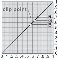
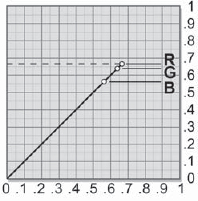
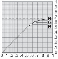
Figure 13-4 illustrates a single pixel's RGB values around the clip point, indicated by the dotted line. With the hard clip shown in Figure 13-5 the red value was seriously lowered but the green and blue were not, which results in a major color shift. With the soft clip in Figure 13-6 the spacing between the RGB values has been gently squeezed together, which lowers the saturation, but their overall relationships have been preserved so that their basic color does not change. The soft clip also helps with the hard edges left around the clipped regions. The soft clip will gently roll off the edges so they are not as objectionable.
If your software can read and write Cineon images but does not offer a soft clip when converting to linear, you can make your own soft clip with a color curve node. Simply draw a soft clip curve like Figure 13-6 that gently clips the Cineon image to whatever white reference you will be using in the conversion to linear. There are now no pixels above the white reference value to get clipped during the conversion.
13.1.2 Linear to Log Conversions
The only file format that the Cineon laser film recorders can read is the 10-bit log Ci-neon. When an 8-bit linear image is ready to be filmed out on the Cineon laser film recorders it must be converted to Cineon. That can be done either at your facility or at the Cinesite service bureau. If the service bureau converts it for you, you will get the default conversions unless you arrange to sit with the operator during the conversion process. If you do it yourself, you can tweak the conversion parameters for the best look.
The fundamental problem here is being able to see what the log version of the image really looks like. There are two ways this might be done. If you are not using Cineon software, Cinesite will give you a viewing utility that can display log images. However, it does not actually use the calibrated Cineon LUTs like the Cineon software does. Instead, it does a fairly close simulation. The other way, of course, is to use the Cineon software and, better yet, also perform the Cineon monitor calibration. For the following discussion we will assume that you have access to one of these methods, either at your studio or at a service bureau.
13.1.2.1 The Conversion Parameters
When a linear image is converted to log, the maximum linear code value (255) is mapped to the white reference point and the minimum code value (0) is mapped to the black reference value in the resulting log image (see Figure 13-7). The display gamma setting will determine the gamma, or brightness of the midtones, in the resulting log image. The default conversions for linear to log are identical to the default log to linear conversions in Table 13-1.
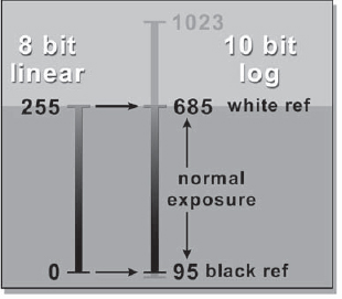
Figure 13-7: Default Linear to Log Conversion
13.1.2.1.1 The White Reference
The maximum linear code value (255) will be mapped to the white reference setting in the log version of the image. For the default setting, the linear code value 255 becomes log code value 685. This does not mean that the log image will contain any pixels with code values of 685, however. Suppose the brightest pixel in the linear image was 200. With the white reference set to 685 the linear 200 would be mapped to log 654, well below the white reference value.
13.1.2.1.2 The Black Reference
The minimum linear code value (0) will be mapped to the black reference setting in the log version of the image. For the default setting, the linear code value 0 becomes log code value 95. Again, this does not mean that the log image will contain any code values of 95, however. If the darkest pixel in the linear image was 20, it would be mapped to log 369, well above the black reference value.
13.1.2.1.3 Display Gamma
The display gamma setting determines the gamma of the resulting log image and is designed in such a way that if you enter the gamma correction you use on your workstation monitor it will convert the linear image to look about right on film. For example, if you set your monitor gamma correction to 1.7, then you would enter a display gamma value of 1.7 during the conversion. If your monitor gamma correction is 1.0, then that is what you would enter. Keep in mind that a video monitor with gamma correction shows only a rough approximation of what the film will look like.
13.2 Working with Cineon Log Images
Kodak's Cineon log images represent the very best image quality for feature film work, but log images are difficult to work with. They cannot be properly viewed on a regular workstation monitor without special setups or utilities and there are several operations, such as compositing, that must actually be performed in linear space. These difficulties are largely addressed when the Cineon compositing software is used, but even with Cineon software there are opportunities to get into trouble with log images.
Most compositing packages today offer some support for the Cineon image format but do not have the comprehensive built-in support that the Cineon software has. However, one can still do feature film work in log space with these packages, given a sufficient understanding of the issues. This section provides explanations of which operations can be done in log space and which have to be converted to linear space, and how to perform the conversions to avoid damaging the image quality.
13.2.1 Viewing Cineon Log Images
Kodak went to a great deal of trouble to solve a fundamental problem in digital film work, which is how to make the image on your monitor look like the projected film. The fundamental problem is that, compared to film, a workstation monitor has a much more limited dynamic range, is the wrong color temperature, and has a totally different response curve to the image data. To see the a close approximation of what the projected film will look like you must be viewing Cineon 10-bit log images on a Cineon calibrated workstation with the following setup:
- The monitor must first be “DAS'd” (Digital Analysis System—pronounced “dazzed”). The factory settings are adjusted to increase its dynamic range—to make the blacks blacker and the whites whiter.
- The monitor LUTs (look-up tables) must be the special Cineon LUTs—no simple gamma curves here. This LUT recreates the print stock's characteristic response curve. Figure 13-8 and Figure 13-9 show the difference between a simple monitor gamma correction curve and the Cineon print film response “S” curve designed for log images.
- The monitor's color temperature is altered from the typical 9000 degrees to the film projector bulb's color temperature of 5400 degrees in the LUT, displaying images in a warmer (redder) hue.
- Turn off all the room lights to create a dark surround environment—a darkened room just like a movie theater. With the monitor DAS'd and the dark surround, the normal contrast ratio of the monitor is boosted from a typical 30:1 up to almost 100:1, which is much closer to the 150:1 of film projected in the theater.
13.2.2 Color Correcting
Cineon log images are fundamentally different from linear images. With linear images the data numbers represent image brightness numbers. With log images the data numbers represent the exponents of image brightness numbers. The same operations on these fundamentally different types of data will produce different results. Following, then, are the rules for color grading images in log space:
Figure 13-8: Monitor Gamma Correction Curve
Figure 13-9: Cineon Log Film “S” Curve
Hue shifts: For example, the image appears too cyan. Add or subtract constants from one or more color channels. If working in normalized colorspace, values such as 0.03 will make a small but noticeable change. If in 10-bit mode (0 – 1023), values such as 30 will make a similar change. In linear space these same color changes would be made by scaling the RGB values about 0.
Brightness: Add or subtract the same constant from all three color channels. The values listed in “Hue shifts” will give small but noticeable brightness shifts. The image will get brighter without increasing contrast or losing saturation. Again, one stop in brightness is 90 Cineon code values. In linear space, brightness is another scaling operation, which also affects contrast and saturation.
Saturation: Saturation operations will work similarly on log images as on linear images.
Contrast: Scale the RGB channels to increase or decrease the contrast, as with linear images.
Gamma correction: You can use a gamma correction operation on log images to adjust the brightness of the midtones as with linear images.
13.2.3 Compositing Log Images
If you are not using Cineon software and simply plug Cineon log images into a compositing node the math will be all wrong and the results truly mortifying. To composite two log images, they must first both be converted to linear, composited, then the results converted back to log. This section describes how to set up the conversions before and after the compositing operation, where to do the color correcting, and how to introduce semi-transparency into your log composites. The setups here are for a typical unpremultiplied foreground in which some kind of matte has been generated such as for a greenscreen shot. Compositing cgi images with log images involves its own special issues, which are covered in Section 13.2.7, “CGI.”
13.2.3.1 Converting Log to Linear
The log to linear conversion operation must be lossless and of the correct gamma. To make the conversion lossless the log image must be converted to either a floating point or 16-bit linear image without any clipping. To prevent clipping, the white reference must be set to the maximum log code value (1023), and the black reference set to 0.
The correct display gamma setting for compositing is 1.7. This gamma value is for setting up the image for a correct composite, not for viewing it on a monitor. Display gamma values of other than 1.7 will alter the edge characteristics of the composited image, making them darker or lighter than they should be. The correct log to linear conversion settings are summarized in Table 13-2.
If a log image is converted to 16-bit (or floating point) linear, then back to log with the settings in Table 13-1, the converted log image will be identical with the original. If the conversion settings are not identical in both directions the converted log image will deviate from the original. As we saw in Figure 13-2, the linear versions of the foreground and background will be so dark that they are unviewable, but that does not matter here because the comp node is the only one that sees them.
13.2.3.2 The Compositing Operation
Within the comp node the foreground scaling operation must be enabled so it will multiply the foreground layer by the matte channel because we are working with unpremultiplied images. This scales all of the pixels around the foreground object to zero black. The comp node will then multiply the background layer by the inverse of the matte to make a “hole” for the foreground element. Then the multiplied foreground and background layers are summed together to form the output of the comp node.
13.2.3.3 Converting Back to Log
The output of the compositing operation is a composited image in linear space that is so dark that you cannot see what it looks like. The last step is to convert the finished image back to log. The conversion back to log space must be done with exactly the same settings as the original log to linear conversions in Table 13-2 or the composited output will not match the inputs. A flowgraph of the basic log compositing setup is shown in Figure 13-10. The Cineon comp node has both the log to linear and the linear to log conversion built in. With other software you would have to add the conversions externally to the comp node, as shown.
Figure 13-10: Flowgraph of Composite
NOTE
Like the example in Figure 13-10, mattes are never converted to log even if extracted from log images. Mattes, alpha channels, keys, or masks all are intended to define the percentage of mix between the foreground and background in a composite or to mask some operation. They are not “images” in the sense that they represent the brightness values of light, so they must never be converted between linear and log.
13.2.3.4 Color Correction
All color corrections to the foreground and background are done in log space prior to the linear conversion. The appropriate location of the color correction nodes is illustrated in the flowgraph in Figure 13-11. The linear versions here are the full range type with the nearly black picture content, so you wouldn't be able to see what you are doing if you tried to color correct them. Use the log image color correction procedures outlined in Section 13.2.2, “Color Correcting.”
13.2.3.5 Transparency
To introduce transparency into the foreground layer for a fade up, for example, the transparency setting within the comp node may be used as usual. The key is, of course, that both the foreground and background layers are linear when presented to the comp node, as shown in Figure 13-12. Inside the comp node, the matte will be scaled by the transparency value to introduce the appropriate transparency into the background and foreground layers during the composite. However, if your comp node does not have an internal transparency control, you can introduce your own transparency into the composite by adding the optional scaling of the matte channel density prior to the comp node, as illustrated in Figure 13-12.
Figure 13-11: Adding Color Correction to a Log Composite
13.2.4 Compositing a Linear Image with Log Images
Sometimes you need to incorporate linear images into your log composites. The source might be an Adobe Photoshop painting, a picture scanned on a flatbed scanner, video elements, or the output of a morph package. Although cgi elements are indeed linear, they have special issues so they are covered separately in Section 13.2.7, “CGI.” The basic approach is to convert the linear image to log and then proceed from that point as if it were any log image.
The key here is to get the linear image into log space looking as close as possible to the desired color grading to avoid abusive color corrections after it is in log space. This is done by refining the default conversion parameters, and usually the only one that needs to be adjusted is the display gamma setting. If you see banding in the log version, try adding grain or noise.
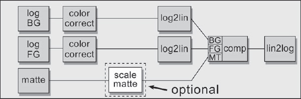
Figure 13-12: Addition of Foreground Fade Operation to a Log Composite
13.2.5 The Screen Operation
Many compositing packages have a “screen” operation. If yours doesn't, see Chapter 5, “The Composite,” Section 5.5.1, for how to make your own. The issue here is how to use the screen operation with log images. The answer is, you don't. Just as in the composite operation, the screen operation must be done in linear space. The log images are first converted to linear, screened together, then the results converted back to log, as shown in the flowgraph of Figure 13-13. The key here is that, like compositing, the conversion from log to linear must also be lossless.
To convert the log images to linear without any clipping, use the conversion settings in Table 13-2. With the white reference set at 1023 and the black reference at 0 there will be no clipping in the resulting linear images. And, of course, the same settings are used to convert the screened linear image back to log space. Any color correction to either image is done in log space prior to the log to linear conversions.
13.2.5.1 Screening a Linear Image with a Log Image
In this situation you have a log background, but an element has been created in Adobe Photoshop or perhaps rendered in cgi and you now have a linear image to screen with the log background. The procedure is first to convert the linear element to log, then follow the procedure for screening two log images. The difference here is in how to convert the linear element to log in the first place.
The trick is to map the original linear image into its proper “position” in log space, and then convert both it and the log background element to linear using the procedure for screening two log elements. It is theoretically possible to leave the linear element as linear, convert the log element to linear, then screen them together. The problem is that the two linear images will not be in the same linear data range and some tricky RGB scaling operations will be needed to match them up. It may seem like unnecessary extra work, but it's much simpler to do the lin/log/lin/log thing. Table 13-3 shows the settings to initially convert the linear element to log for a screening operation:
| Table 13-3: Linear to Log Conversions for a Screen Element | ||
| Settings | Remarks | |
| White reference | 685–1023 | Adjust to taste |
| Black reference | 0 | Must be 0 |
| Display gamma | 0.6–1.7 | Adjust to taste |
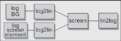
Figure 13-13: Flowgraph for Screening Log Images
In this case, there are no secret underlying mathematical relationships to preserve, as there are with the compositing operation. You can raise the white reference to brighten the highlights or lower the gamma to increase the contrast if you wish, but do not raise the black reference. If the black reference does not stay at exactly zero, what were zero black regions in the linear version will become greater than zero in the log version. This will introduce a light haze over the entire output image.
As in the compositing setup, color correction of the screen element should be done on the log versions of the images. Make certain that any color correction operations do not disturb the zero black background region, however. Remember the haze. A wise precaution would be to compare the log output of the screen operation to the original log background plate to ensure that no overall subtle color shifts have occurred.
13.2.5.2 The Weighted Screen
We saw how to perform the weighted screen operation on regular linear images in Chapter 5, Section 5.5.2. The same thing can be done when screening with log images, but the scaling operation to introduce the “weighting” on the background plate must be done in linear space. The scale RGB operation on the linear version of the background (BG) in Figure 13-14 is where the background plate is scaled down to weight the screening operation. However, the luminance matte (“screen matte” in Figure 13-14) is made from the log version of the screen element.
13.2.6 Matte Paintings
Here we address the situation of how to create a digital matte painting for compositing that is color matched to a log image. This usually means painting on a frame of the film to create a new version that will be used as a background plate or creating a totally separate foreground element to be composited over log images. Either way, the linear painting must end up back in log space and color matched to the other log elements.
The basic problem to overcome is that the painting must be created in linear space but the log elements it is to color match are in log space. First convert a Cineon log image to linear as the color match reference using the default conversion settings in Table 13-3. The painting is then made to match the linear Cineon image, and the finished painting is converted back to log for compositing. The key issue is to make certain that exactly the same conversion settings are used when converting the original log image to linear as when converting the finished linear painting back to log.
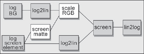
Figure 13-14: Flowgraph of Weighted Screen Operation
13.2.6.1 Tips and Techniques
The single most important thing you can do in this process is to the test the entire conversion pipeline from log to linear and back to log before doing any painting. There are problems that can be seen only in linear space on the paint station that will require revisions to the log to linear conversion settings. There are other problems that can be seen only after the painting has been converted back to log that will also require altering the linear to log conversion. It is best to find and fix them all before the paint artist has invested hours on a wasted paint effort. Following are some issues you may encounter and some suggestions on what to do about them.
The Cineon image is too light or too dark on the paint station. If the gamma correction of the paint system is very different from the default display gamma used in the conversion, the image may be too light or too dark to work with. Reconverting it with a revised display gamma may be necessary. To make the linear version lighter, lower the display gamma. To make it darker, raise it. Another alternative is to adjust the monitor gamma of the paint station to compensate, but many painters will object to this because it disrupts the normal appearance of their GUI.
There is clipping in the linear version. There may be times when the areas to be painted contain superwhite pixels that are above the default white reference and are clipped out with the default conversion. An example might be painting on a snow-capped mountain peak. To retain the superwhite detail, the white reference will have to be raised. If this is done, however, the midtones will get darker. If this is objectionable, a possible solution is to lower the display gamma to compensate.
If the superwhite picture information is not in the areas that are being painted, don't raise the white reference. The resulting painting will have areas that are clipped at the white reference, of course, but these can be restored after it is back in log space. Just mask the superwhite areas out of the original log image and composite them over the painting to create a version with restored superwhites.
There is banding in the painting after it is converted back to log. Using a 16-bit paint system will prevent banding, of course, due to the increased data precision. If you are using an 8-bit paint system, there are two things you might do. First is to add some grain or noise to the painted regions. When they lost their grain in the painting process they became banding fodder. The second thing is to lower the display gamma from 1.7 to perhaps 1.0 when converting the original log image to linear. The higher the conversion display gamma setting the greater the tendency for banding. The problem, of course, is that the image will appear too dark on the paint station. Changing the gamma of the paint monitor will compensate for this.
The linear image does not look identical to the log image. Yes, we know. Don't expect the linear version on the paint system to appear absolutely identical to the log version on a workstation with Cineon LUTs. In addition to any clipping, the linear version may appear a bit bluer, the brights will increase in saturation, while the midtones and darks can lose contrast and saturation. These are unavoidable differences between the appearance of a linear image displayed on a monitor with a gamma correction and a log image with a Cineon LUT. The most that can be expected of the linear version is that it be reasonably close.
13.2.7 CGI
Most studios render linear cgi images and then convert them to log for compositing with the live action. Although it is technically possible to actually render log cgi images directly, it is a nontrivial process that is outside the scope of a book on digital compositing. The fundamental problem with linear cgi elements is that they look different after they are in log space. There are two places where the cgi can become abused. The first is in the initial render and subsequent conversion to log space, and the other is in the actual compositing operation itself. In this section we first look at the rendering, then the compositing of cgi elements with log images.
13.2.7.1 Rendering
The most common arrangement for creating a cgi element to composite with live action is to have some color corrected frames of the background plate available to the cgi artist to do “test comps” so that the color and lighting of the cgi can be checked against the intended background. All too often, however, when the cgi is delivered to the digital artist and composited in log space, serious color shifts occur, followed by frenetic color correction efforts to put things right. Although linear images are never going to look exactly the same when converted to log, with the proper setup throughout the 2D and 3D production pipeline they can be made very close.
The starting point is the gamma correction on the cgi workstation monitor the test comps are being done on. Set the workstation gamma correction to 1.7 and use this number for all of the display gamma settings in all of the lin/log conversions everywhere in the pipeline. Again, if your workstation reports only the end-to-end gamma rather than the actual gamma correction you will need to confirm that the end-to-end gamma is 1.5, which means that the gamma correction is 1.7. With the monitor gamma correction safely set, let's step through the operations to set up a correct cgi render.
Step 1: Convert some color corrected log frames to linear for the 3D department to use as background plates for the test comps:
- White reference = 685
- Black reference = 0
- Display gamma = 1.7
The white reference is 685 because that is default for a normally exposed negative. If the cgi must match some elements brighter than 685, the white reference can be raised higher to avoid clipping them out. However, keep two very important things in mind here. As the white reference is raised the midtones get darker, so the resulting linear image will look less and less like its log counterpart. This is not a problem in the long run, because the cgi will be matched to the darker reference and get lightened back up when it is converted back to log. The problem will be that it is much harder to color match with the darker colors, and small discrepancies will become magnified when the cgi is converted to log. To help with this, the workstation gamma could be cranked up briefly to check the color match in the darks.
The second issue is that whatever white reference is used here must also be used when initially converting the cgi to log at Step 4. Small deviations here will have large effects on the brightness of the log version of the cgi.
Note that the black reference is set to 0 here. This is essential, and is done specifically for cgi renders. The reasoning goes like this: The output of the cgi render surrounds the cgi element by a zero black field. When this is later converted to log, it must stay zero (not raised to 95) or else the blacks will pop up a bit in brightness. All lin/log conversions must share exactly the same settings; therefore the zero black reference must also be used in the initial log/lin conversion of the Cineon background plate.
Step 2: Render cgi images and perform test comps over the linear Cineon background plates. Make certain that the test comp monitor gamma correction is set to 1.7. The cgi elements are then delivered to the compositing folks.
13.2.7.2 Compositing
We now step into the compositing department and follow the action there. While the steps that follow may seem like we are whip-sawing between linear and log space, the sequence of operations is driven by the following unrelenting logic:
- The unpremultiply operation must be done in linear space for the math to work properly.
- The cgi must be color corrected in log space because the Cineon film LUTs used for log work make linear images unviewable.
- The compositing operation must be done in linear space for the math to work properly.
Step 3: Bring the linear cgi element into the compositing flowgraph (Figure 13-15) and perform the unpremultiply operation on the linear version. See Section 5.4, “Compositing CGI Images,” in Chapter 5 for a review of this topic. Again, if you are not going to do any color correcting to the cgi element (it could happen!) you can skip the whole unpremultiply thing, leaving the cgi premultiplied. If you do, you must turn off the scale foreground operation in the comp node at Step 6.
Step 4: Convert the RGB channels of the cgi element to log space (not the alpha) using the same settings as used in Step 1. The linear image is then properly positioned into log space and from this point on it has lost all “linear identity.” It is now just another log image, but one that has no code values greater than the white reference used to convert it from linear to log. We now have an unpremultiplied log element that is ready for color correction.
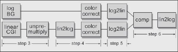
Figure 13-15: CGI Compositing Flowgraph
Step 5: For the compositing operation, convert the RGB channels of the unpremultiplied color corrected log cgi element to linear with the following settings:
- White reference = 1023
- Black reference = 0
- Display gamma = 1.7
These are the standard settings for a lossless conversion of a log image to linear just before compositing, as listed in Table 13-2. This time we avoid any clipping by keeping the entire dynamic range of the log image when converting it to linear by setting the white reference to 1023.
Step 6: The comp node is set to scale the foreground because we have an unpremultiplied foreground image. If the unpremultiply operation was skipped in Step 3, turn off the scale foreground operation. After the compositing operation the composited linear image is converted back to log space using the same settings as in Step 5.
13.2.8 Transformations and Blur Operations
Theoretically, all image transformations (rotate, scale, etc.) and blurring operations should be done in linear space. The reason is that all of these operations entail filtering (re-sampling) the brightness values of the pixels. But log images are not brightness values. They are exponents of brightness values, so the math does not work out right. In general, what goes wrong is that very bright pixels next to very dark pixels get filtered down to too low a value and get darker faster than they should.
In the real world, however, pixels in the normal range behave fairly normally, so most of the time you can ignore this issue and perform transformations and blurs in log space. Just keep this little insight in the back of your mind so that one day when a problem arises you can whip it out and amaze your friends by knowing exactly what the fix is. If you wind up needing to convert to linear for one of these operations, use the full range conversion settings in Table 13-2.
If you would like to see a demonstration of this issue, take a log image of a starfield and give it a moderate blur. Now go back to the original log starfield, convert it to a full range linear image, give it the same blur, and convert it back to log. When the two versions are compared, the stars blurred in linear space will be much brighter than the ones blurred in log space.