
11. A Super Project To Test Out Your New Skills
What You’ll Be Doing
![]() Watch as Coolcrafter10 gets an invitation at the ocean
Watch as Coolcrafter10 gets an invitation at the ocean
![]() Inventory your Tinkercad skills and tools
Inventory your Tinkercad skills and tools
![]() Learn all about custom objects found in the Shape Generator
Learn all about custom objects found in the Shape Generator
![]() Line objects up with the Align tool
Line objects up with the Align tool
![]() Cover your futuristic city with glass domes
Cover your futuristic city with glass domes
Coolcrafter10 sat on the cliff’s edge with Didgee, PackRat, and Prism and watched the sun dip beneath the horizon. It had been a full day of exploration, and the four friends had come up with many ideas for how to expand their new city.
“I think using some track and adding a rail system that goes all around the city would be useful,” said PackRat. “That way we could get from place to place quickly, without having to run.”
Prism nodded and pointed at a constellation that had appeared overhead. “Is that the Big Crafter?”
“Yep,” said Didgee as she pointed to another constellation to the left. “And there’s the Little Crafter.”
Coolcrafter10 stared up at the stars and then down at the city floating in the middle of the ocean. Over the past few days, he had learned more about creating and crafting than he’d picked up in three months before that. A few months ago, Coolcrafter10 would have been building a castle or statue block-by-block, and it would have taken weeks or months to complete some of his big plans. He smiled at Didgee. “You know, if you hadn’t come walking by my field that day, we would have never met, and I would never have known about any of these great tools you’ve shown me.”
Didgee shook her head. “I doubt it. The secret about Minecraft and the worlds we visit is how fast information travels. I show you, you show your neighbor, and your neighbor shows someone else. And so on and so on. What you’ve learned today might have just taken a bit longer to reach you.”
“She’s right,” said Prism. “Since Didgee left on her last exploration, I’ve shown about a dozen neighbors and visitors how to use MCEdit and Tinkercad, and these are people who have their own neighbors and friends in other worlds. They’ll spread the news, and many more crafters will gain the knowledge to do what we do.”
Didgee nodded in PackRat’s direction. “Would you believe that PackRat didn’t even know how to use a crafting table a few weeks ago?”
PackRat’s face turned red. “Didgee!”
“I’m not making fun of you. We all started out knowing very little about Minecraft. I’m just saying that we are all capable of learning new skills really fast,” said Didgee. “You’ve gone from a newbie crafter who couldn’t use a crafting table to creating 3D models of the amazing sculptures you’ve imported with MCEdit!”
PackRat grinned. “That’s true. I could never have imagined I’d be building these huge structures in such a short time.”
“And now Coolcrafter10 here has learned how to do this stuff and can help spread the word when he heads back to his home,” said Didgee.
Coolcrafter10 thought about returning home soon. His little corner of the world was ready for whatever he could create and add to it, with plenty of flat areas and hills and even a nearby lake. But as he thought about leaving Didgee and the others, he grew sad.
Prism looked at Coolcrafter10 and shook her head. “I don’t think he likes the idea of heading home.”
“I don’t,” said Coolcrafter10. “I’ve had so much fun with all of you that the idea of returning to my big empty castle isn’t very appealing.”
“Then don’t go back,” said PackRat. “Look around you. Look at that brand-new city floating over the ocean. Do we look like we don’t have room for you to join us?”
Didgee laughed. “I’m sorry, Cool. I had no idea. I figured you’d want to go back to your own castle, but I guess it would be pretty lonely. I’m with PackRat…Don’t go. Stay with us!”
Prism nodded. “Yes, please do!”
“Are you serious?” asked Coolcrafter10. “You’ve only known me for a short while.”
“It’s already a done deal,” said Didgee. “You’re staying. And since you already have the skills that we’re all using, you’ll be a valuable addition to the team. And with that city over there, we’ll probably meet some new crafters who will want to stick around and explore and learn and try to find new ways to do things.”
Coolcrafter10 looked up at the stars and smiled. “The skills are great, but add that to having three new friends, and I just don’t know what to say right now.”
“Say you’ll stay, dude,” said PackRat.
“Yes, please stay,” said Prism.
Didgee smiled and nodded. “Just nod and say okay.”
“Okay,” said Coolcrafter10 with a nod.
The three friends clapped and patted him on the back, and everyone smiled and laughed as they slowly turned their attention back to the water. Far out across the water, they could see the light from a lighthouse. Someone out there was providing a light for explorers visiting a different shoreline.
“I’m going to find out who that is,” said Didgee. “I’ll be leaving again in a few days. Want to come with me, Cool?”
Coolcrafter10 nodded. “Sure. Do you know how long we’ll be gone?”
“A few days or so. We’ll visit and see if the lighthouse owner has anything we can learn, and we’ll share what we’ve learned. Then we’ll come back and see if Prism and PackRat have anything new to share.”
“You know we will,” said Prism. “As a matter of fact, now that I’ve figured out this rotation thing in Tinkercad, I’ve got a few new ideas to test out.” Prism opened up her laptop but then looked at her friends and closed the lid. “It can wait until tomorrow, though.”
Coolcrafter10 pointed up in the sky. “Hey, that’s Builder’s Belt!”
The stars twinkled a bit brighter in the sky, and the four friends talked all night about their plans.
You’ve Got Skills!
You’ve picked up quite a few new skills in Tinkercad. By now, you should be getting quite comfortable dragging and dropping shapes, rotating and merging, shrinking and enlarging, and creating holes through solids. You use these basic skills to turn take simple objects (such as boxes and spheres) into more complex objects.
But don’t forget that Tinkercad and other CAD applications allow you to import objects created by other people. And you can shrink, stretch, rotate, and group together those imported objects with other objects. I hope you’re beginning to understand that you have most of the skills you need to create some incredible 3D models for importing into your Minecraft worlds. But there are still a few more secrets I need to reveal.
In this chapter, I show you a few more features that Tinkercad offers when it comes to creating 3D models for your Minecraft worlds. Once you’ve finished this chapter, you will have learned the skills that are most useful and popular, but there’s plenty more to learn about Tinkercad. It’s up to you to dig a little deeper to discover the rest of Tinkercad. And keep in mind that the Tinkercad team is always working to add new features and tools, so there’s always going to be something new to learn.
So, let’s jump right to it and take a look at two additional features that you’ll want to try out: Shape Generator and Align. The Shape Generator lets you take pre-created shapes (made by the Tinkercad community) and fine-tune them with a control window. The Align feature lets you center objects around either a shared axis or an edge.
The Shape Generator
You can find the Shape Generators tab on the right side of the Tinkercad screen, just below the Import tab. When you open it, by clicking on the small triangle to the left of its name, it looks as shown in Figure 11.1.
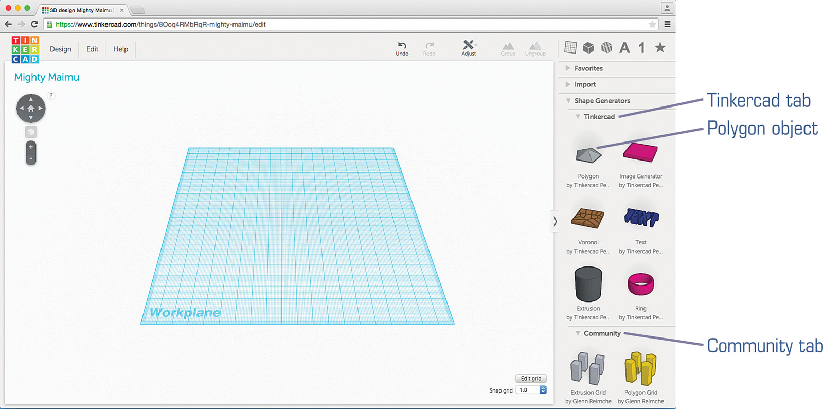
Inside the Shape Generators tab are three subtabs, labeled Tinkercad, Community, and Your Shape Generators. The Tinkercad tab currently offers six objects that you can customize by using a control window.
As an example, in Figure 11.2 I’ve dragged a Polygon object onto the workspace. You can see a control window to the right of the object.

In Figure 11.2, the Polygon has five sides, but in Figure 11.3 you can see that I’ve increased the number of sides to eight by using the # of Sides slider. If I want to shrink or enlarge the object, I can either use the white control squares or move the Size and Height sliders in the control window.

Objects in the Shape Generators tab don’t all have the same configuration settings in their respective control windows. For example, Figure 11.4 shows what the window looks like for a Text object.

Note
Custom objects behave like normal objects
Shape Generator objects behave like any other objects you create in Minecraft, and they aren’t limited to the control window configuration options. You can rotate them, turn them into Hole objects, and much more. The control window for an object typically offers up options that are difficult to change (or impossible) using the basic Tinkercad tools.
After dropping the Text object, I can change the text to anything I like by clicking in the Text box and typing in different text. Figure 11.5 shows that I’ve changed it to my first name, modified the font with the Font drop-down menu, and decreased the height a bit.

The Text and Polygon objects you’ve seen so far in this chapter are available on the Shape Generators tab under the Tinkercad tab, but you aren’t limited to the options on this tab. Dozens and dozens of other objects have been created by the community of Tinkercad users and made available for your use. You find them logically enough on the Community tab.
Note
Custom shapes require more learning
You can create your own custom shapes and submit them for inclusion in the Community tab, but keep in mind that creating custom shapes requires some programming skills that are beyond what I can cover in this book. To begin creating a custom shape, scroll down below the Community tab and click on the New Shape Generator button on the Your Shape Generator tab and read the simple instructions provided there. For more help on creating your own custom shapes, check out the following site: https://api.tinkercad.com.
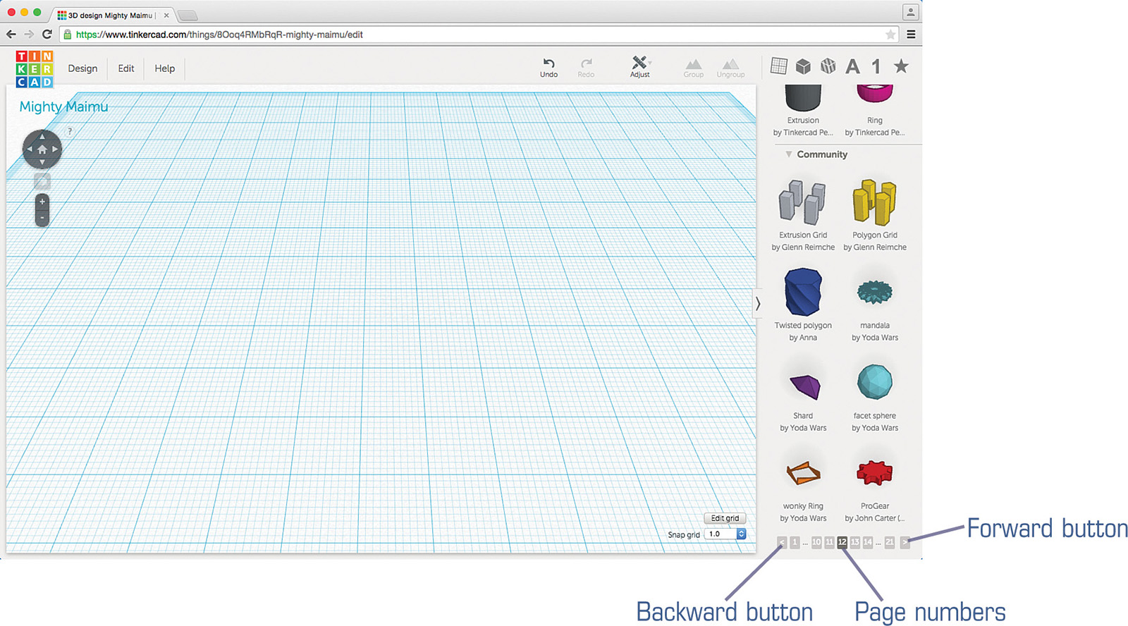
The Community tab displays eight custom objects at a time. To view more, you can move forward or backward through the library by clicking on the small arrows at the bottom right in Figure 11.6. You can also click on a number in the bottom right of the screen to jump to a particular page. In Figure 11.6, you can see that I’m on page 12 because the 12 is darker gray than the other page numbers.
If you’ve ever been to a popular tourist attraction in Florida, you may recognize the shape I’ve dropped onto the workplane in Figure 11.7. It’s a custom object, and the only thing I can change about it in the control window is the radius.

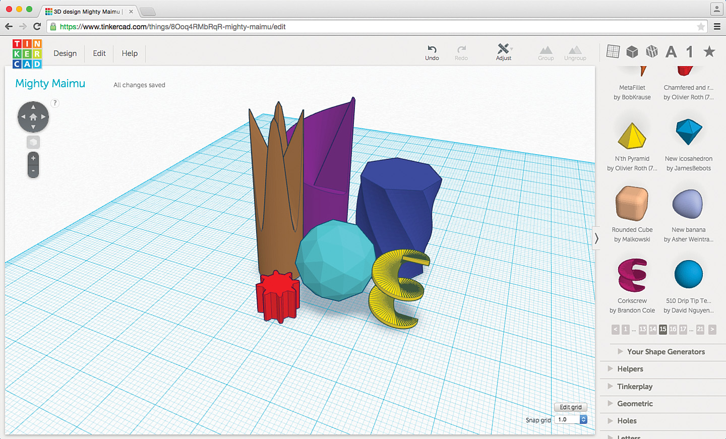
I like a lot of the shapes I’m seeing on the Community tab. Once again, a futuristic city is beginning to take shape, as you can see in Figure 11.8.
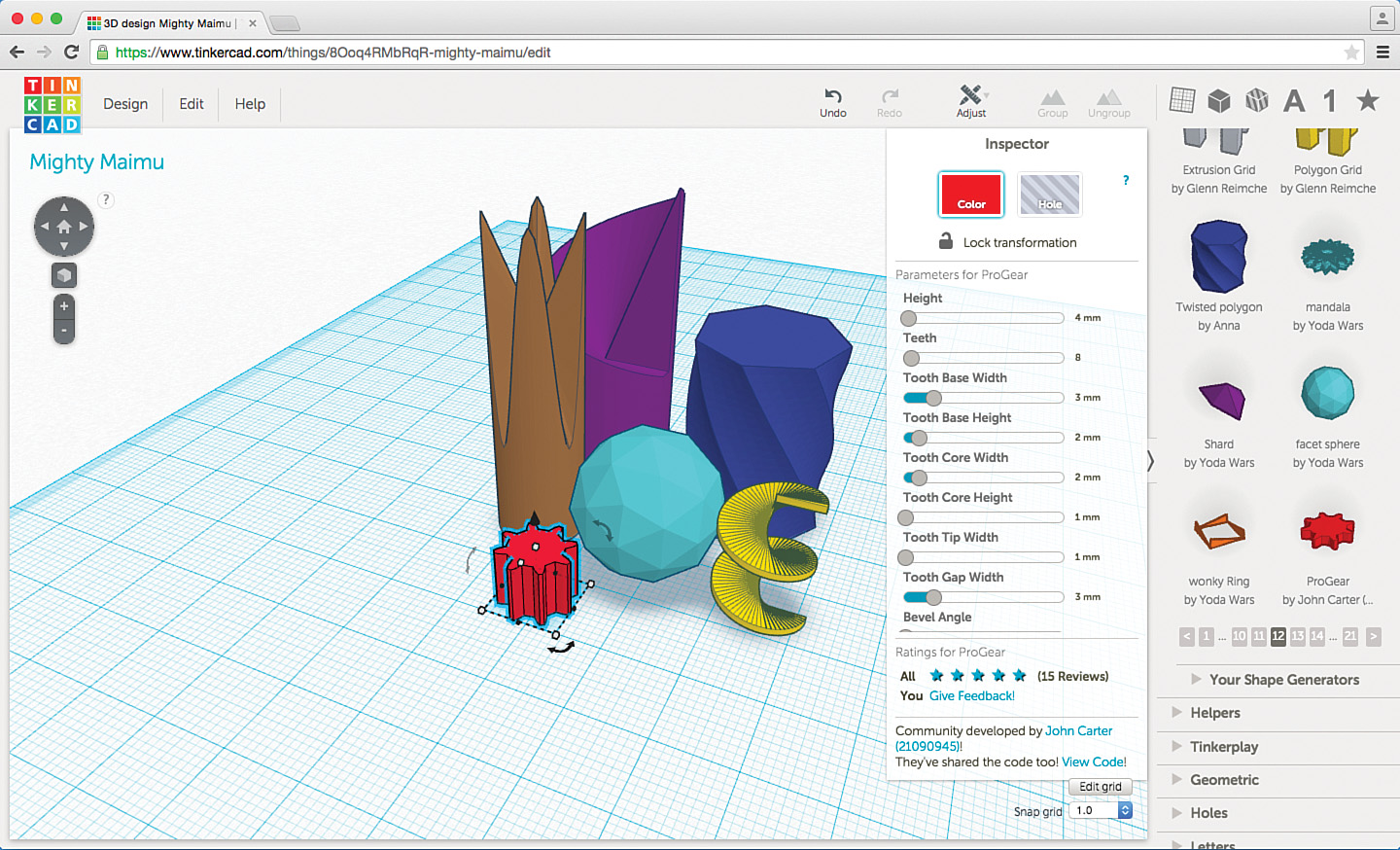
Each of these objects has a control window with unique configuration options. The most complex control window is for the ProGear object, shown in Figure 11.9. Look at all the configuration options!
The Shape Generators tab is a fun tool to use. You can make all kinds of crazy shapes and designs with the objects it holds. You can then combine your special objects with basic objects (such as a Box object or a Sphere object) to make larger and more diverse 3D models.
I’m quite happy with my new little city, but before I move on to the next Tinkercad tool, I’d like to point out something for your consideration. Notice in Figure 11.8 that all the various shapes have unique colors. You can easily select all the objects and group them so they can be resized together (making them larger or smaller), but anytime you are importing multiple objects into Minecraft with MCEdit, one thing you might want to think about is whether or not you intend to change the materials of your imported objects to other materials.
For example, if you import a red sphere with MCEdit, that sphere will be pulled in and assigned a material that is close to its original color. When I imported just a red sphere with MCEdit, the sphere ended up being made of brick block. Remember that you can select an object (or multiple objects) in MCEdit and use the Fill and Replace button to change one material to another.
If I were to group the objects shown in Figure 11.8, they would end up all consisting of the same material in Minecraft. This might not be a big deal in some cases, but for this city, I’d like each building to be a unique material. This will not only provide a nice colorful city to explore but will also make it easier to select a single building and change its material if I wish to do so.
Knowing how to carefully select the colors of imported objects is going to be important later in this chapter, when I import this city into a Minecraft world. But before I show you why this will be important, let me show you one final tool that can be helpful for making sure objects line up or stack symmetrically.
Note
Get in the habit of saving your work
I’ll return to the futuristic city in Figure 11.8 shortly, so be sure to save it if you are following along with my instructions and then create a new project before you try out what I show in the next section.
The Align Tool
Take a look at the two objects in Figure 11.10. I’ve placed a Box object (flattened a bit) and a Pyramid object on the workplane.

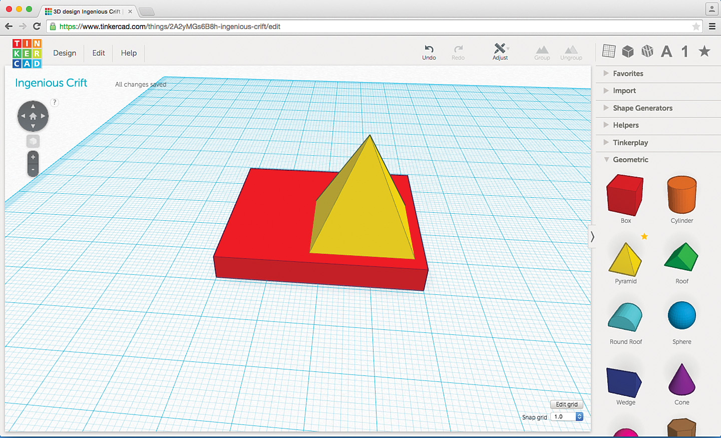
I’d like to stack the pyramid on top of the box object and center it so there’s an equal amount of space on the left and right sides as well as the front and back. In Figure 11.11 you can see that I’ve raised up the pyramid a bit and dragged it onto the box.
There’s a bit more space to the left of the pyramid than there is on the right. Also, the pyramid is a bit closer to the front edge of the box than it is to the back. The workplane is gridded, so I can use the grid lines and the mouse to move the pyramid until an equal number of grid squares are on the left and right (and in the front and the back), as shown in Figure 11.12.

Using the grid lines to center two or more objects, however, won’t always work, and it can be a bit frustrating to count grid lines and try to drag objects carefully. Of course there’s a better way.
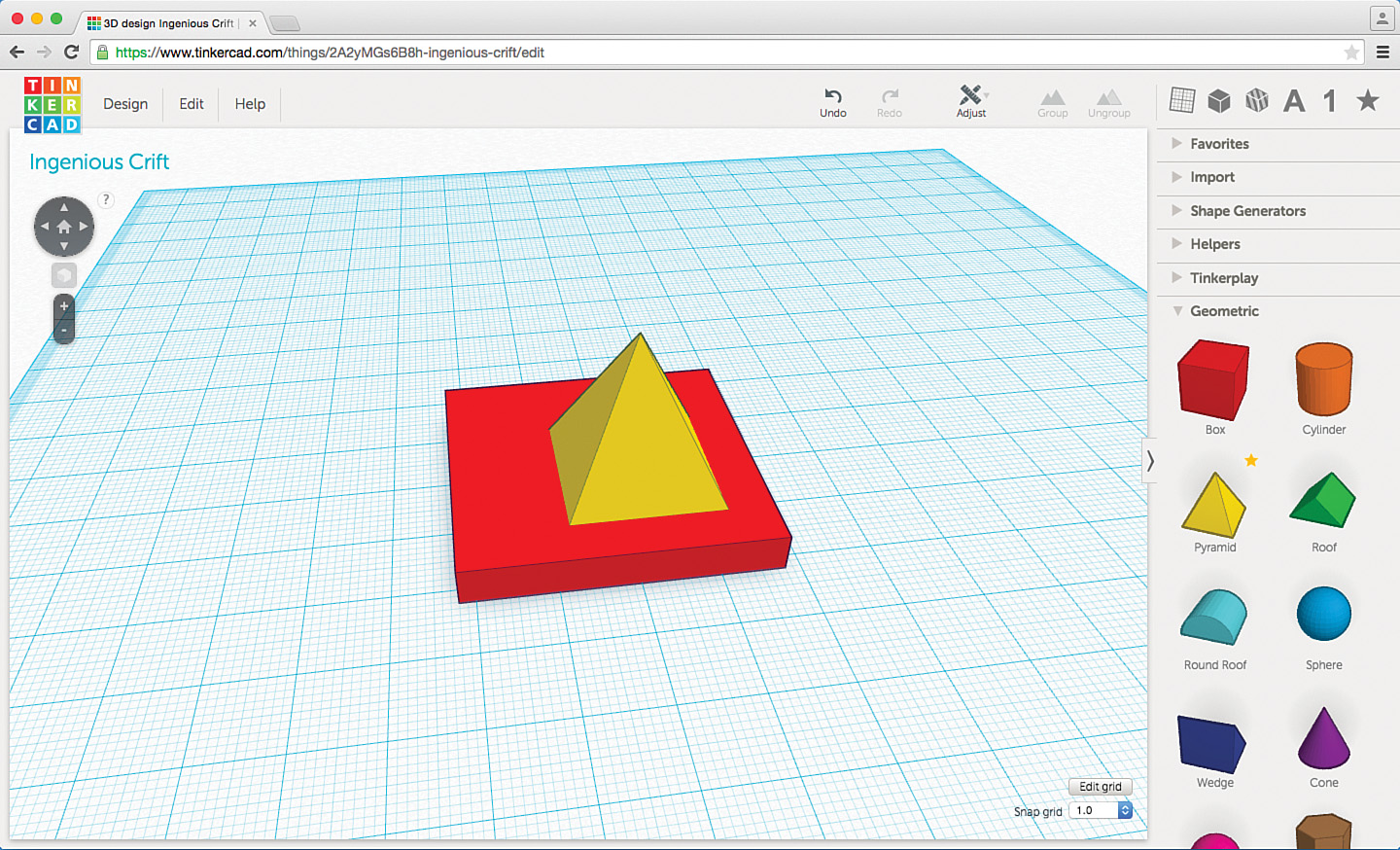
In Figure 11.13, you can see that I’ve dragged the pyramid to the front-right corner of the box so you can easily see that the two objects are not even close to being centered with each other.
Tinkercad makes it easy to center objects left to right and also to center objects front to back. And it lets you easily do both. Also, it helps you align objects so they share an edge. Let’s take a look at how to do all of these operations.
First, I’ll walk you through how to center these two objects left to right. To do this, you must select all the objects you wish to center left to right. After selecting the box and pyramid, click on the Adjust menu shown in Figure 11.14 and select the Align option.

After you choose the Align option, a bunch of dots appear around the objects, as shown in Figure 11.15.
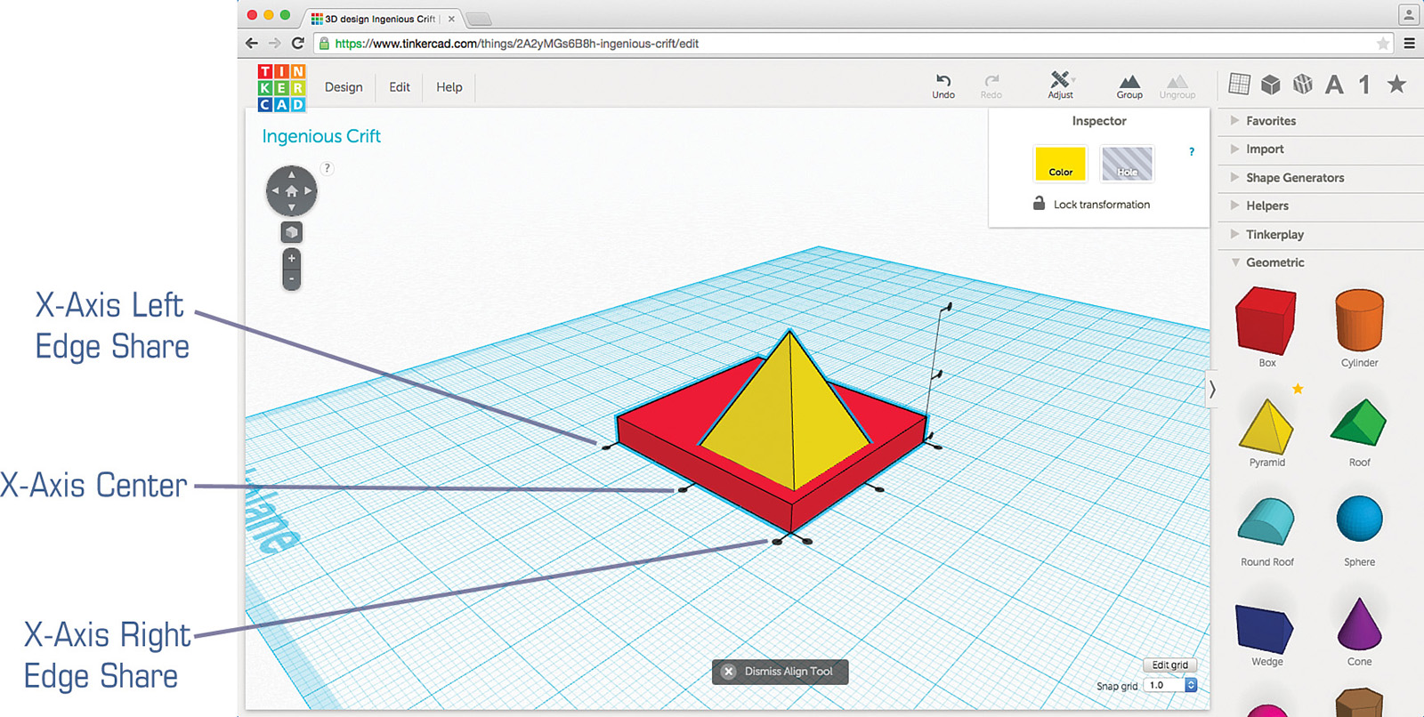
These are alignment dots, and you can see that there are nine of them in all. Three dots are used for the X-axis, three for the Y-axis, and three for the Z-axis.
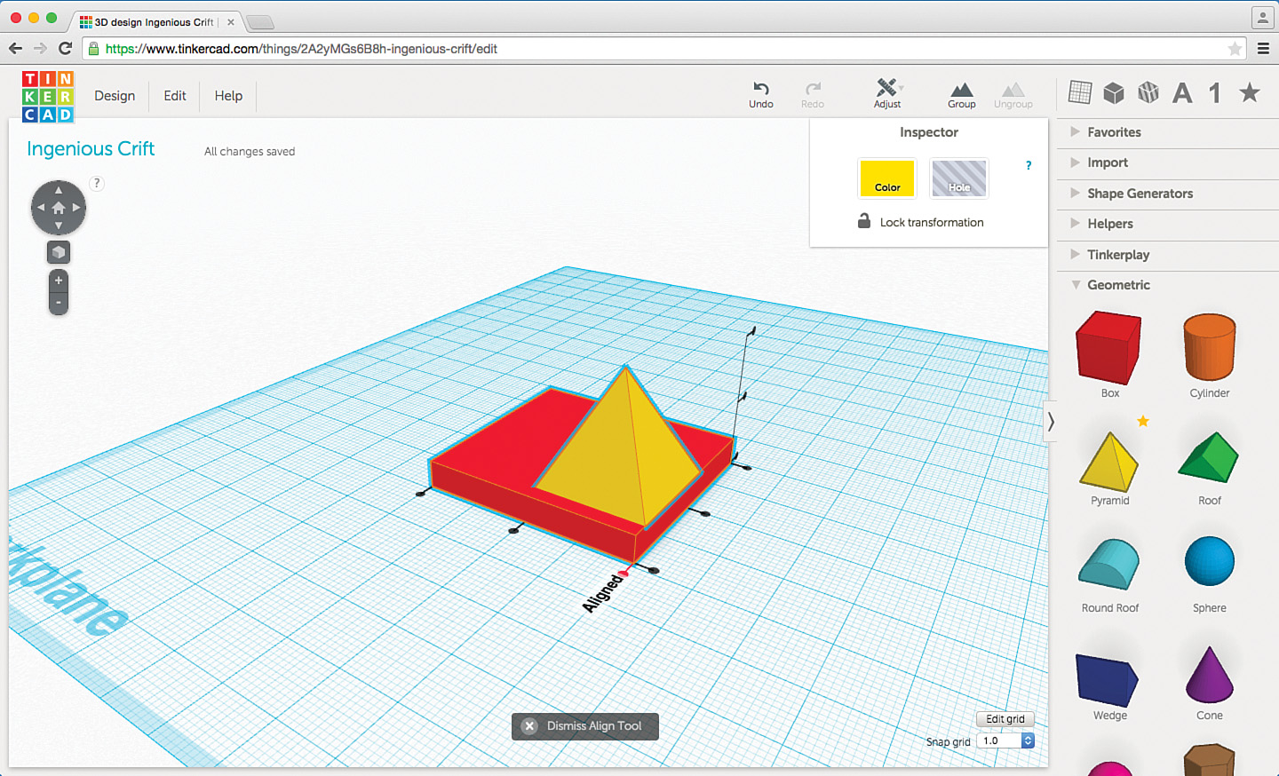
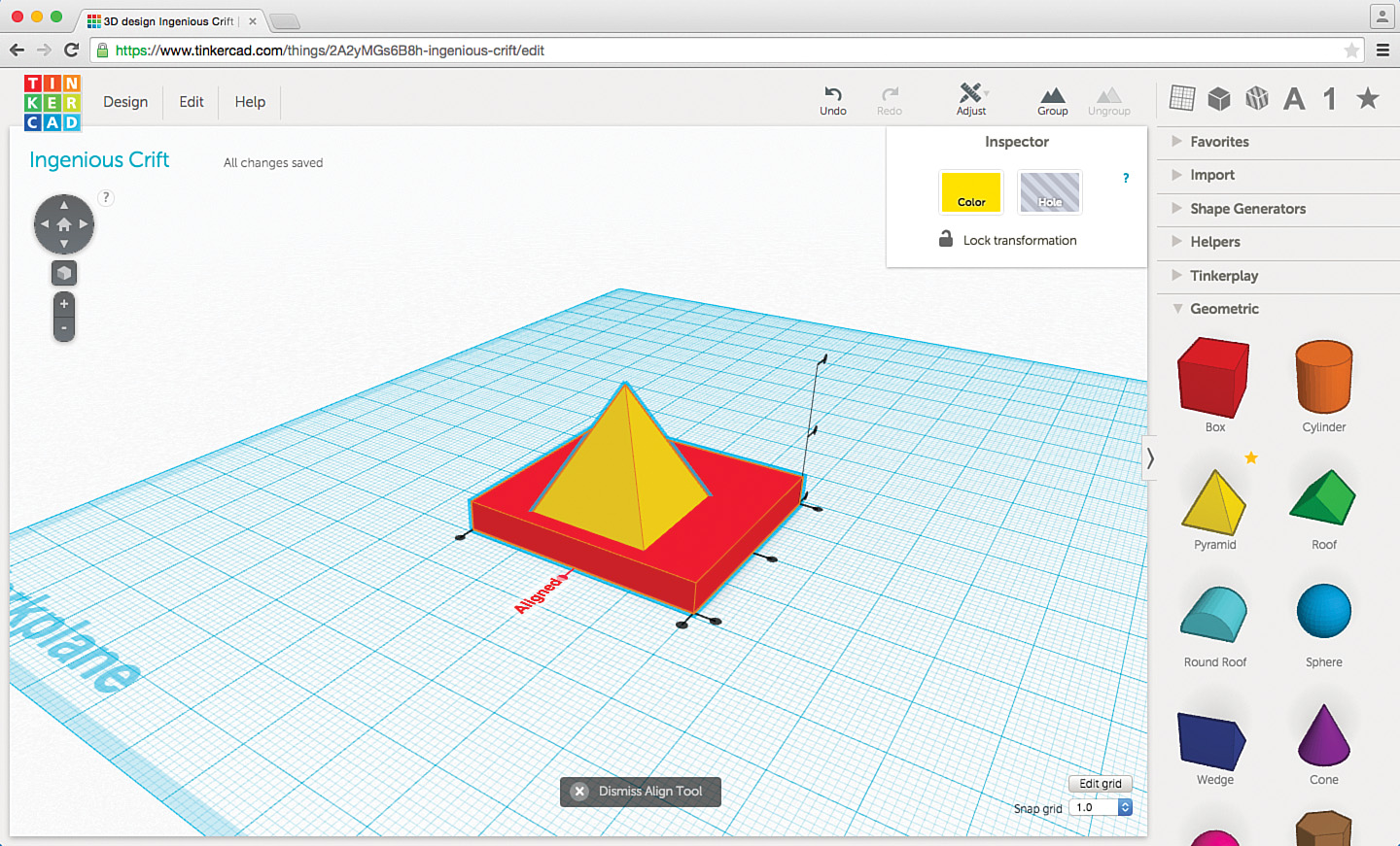
Centering left to right corresponds to the X-axis, so you need to use the three dots that run along the front of the object. If you click on the X-Axis Left Edge Share dot, both the pyramid and box will share the leftmost edge, as shown in Figure 11.16. You even see the word “Aligned” on the workplane so you know that the action is done.

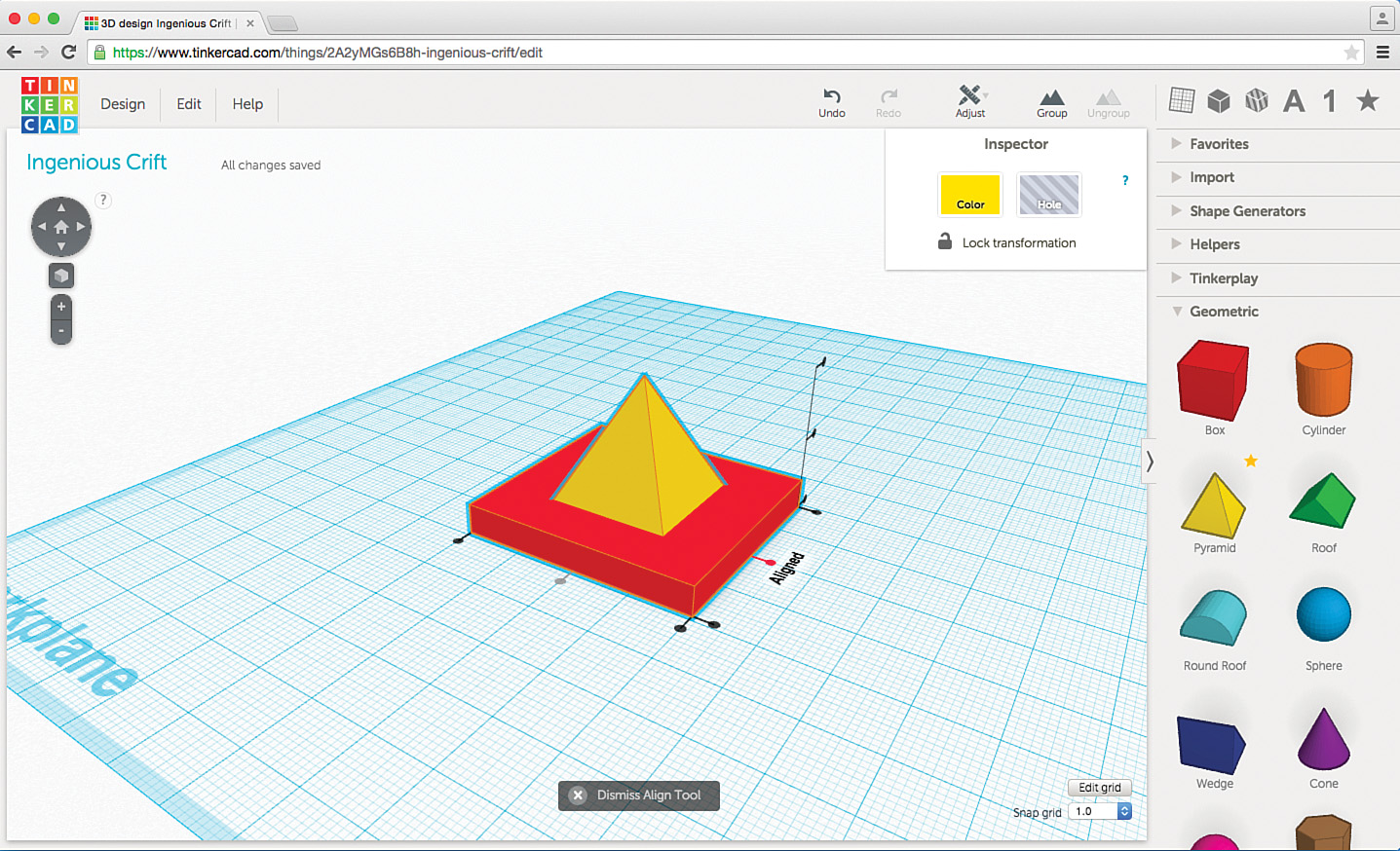
Likewise, you can click on the X-Axis Right Edge Share dot to align the two objects along the right edge, as shown in Figure 11.17.
To center left to right, click on the X-Axis Center dot, and Tinkercad centers the pyramid on the box, from left to right, as shown in Figure 11.18.
Now that the pyramid is centered on the box from left to right, what about front-to-back? You just click on the Y-axis dots to align on the front edge, back edge, or centered. Figure 11.19 shows when happens when you use the Y-Axis Center dot to center the pyramid on the box front-to-back.
Just for fun and to see how the Align tool can be used, take a look at Figure 11.20, where I’m trying to “balance” a sphere on top of the pyramid.

It looks centered, but the only way to be certain is to use the Align tool. To do this, select only the pyramid and the sphere and then click on the Adjust menu and select Align. Once again, you get the alignment dots, as shown in Figure 11.21.
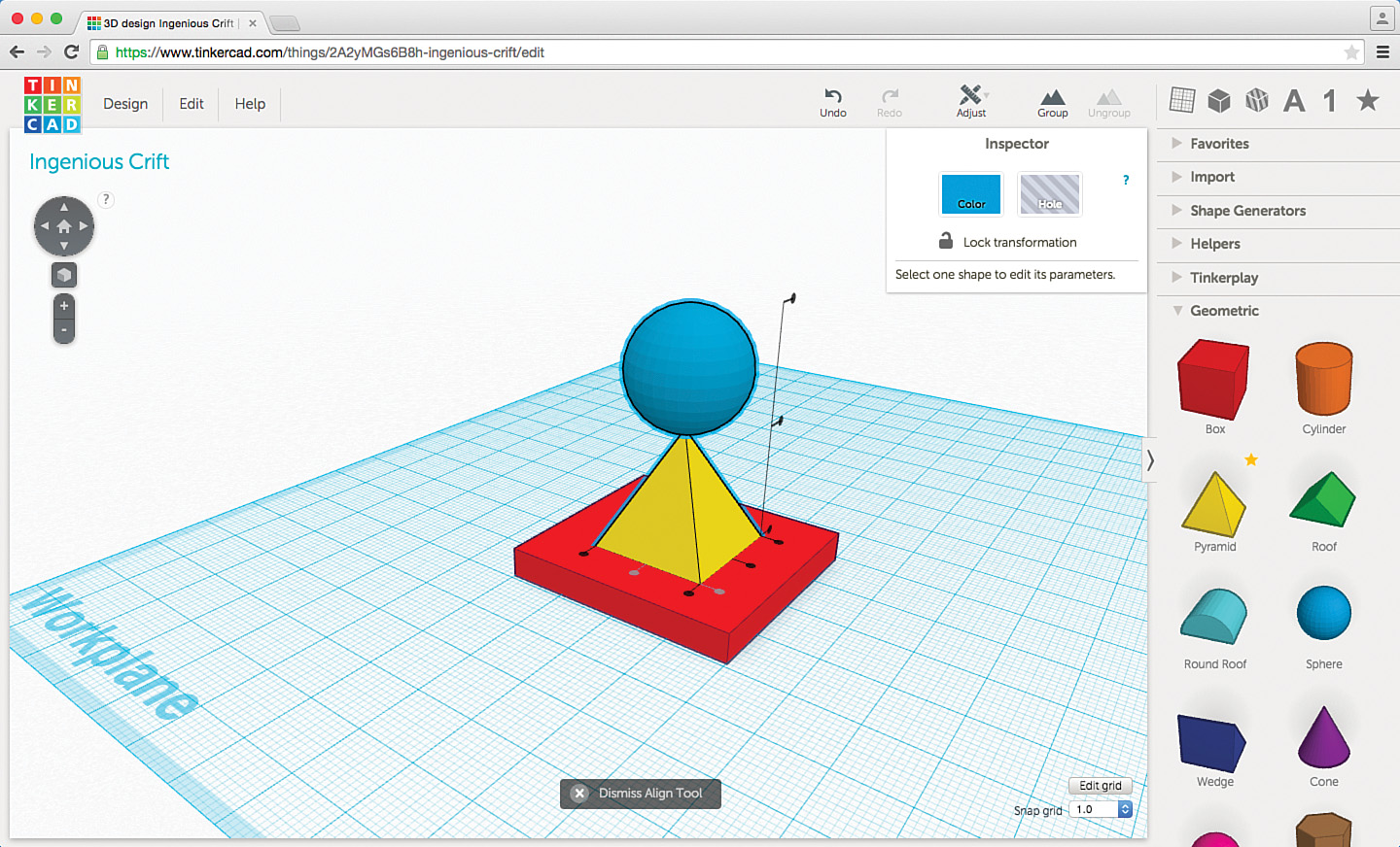
Then click on the X-Axis Center dot and the Y-Axis Center dot, and you end up with the sphere perfectly balancing on the sharp tip of the pyramid.
Although you haven’t yet seen the Z-axis alignment dots in action, you can probably figure out how to use them. If you need two or more objects to share their bottom or top edges, you click on the Z-Axis Top dot or the Z-Axis Bottom dot. The Z-Axis Center dot simply matches up two or more objects so they are perfectly centered from top to bottom. Using a combination of the X-Axis Center, Y-Axis Center, and Z-Axis Center dots, you can center a sphere inside a box, as shown in Figure 11.22.

Dome Cities
Now it’s time to return to that futuristic city I teased you with back in Figure 11.8. Recently I watched an old science fiction movie where a bunch of cities were covered by clear domes with walkways and tunnels that allowed movement between cities. Such a setup might be fun to create using all the various Tinkercad skills you’ve learned so far.
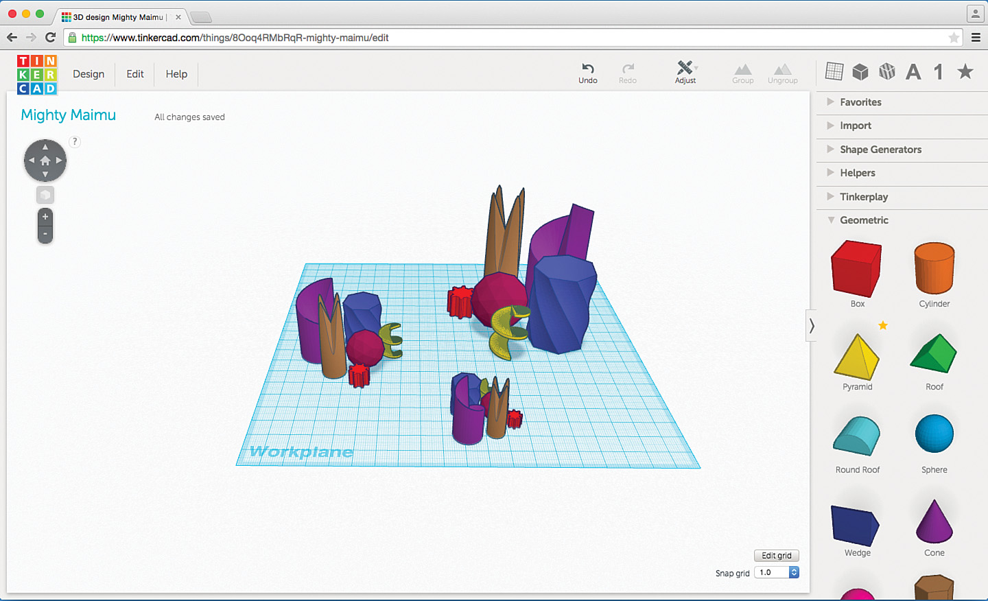
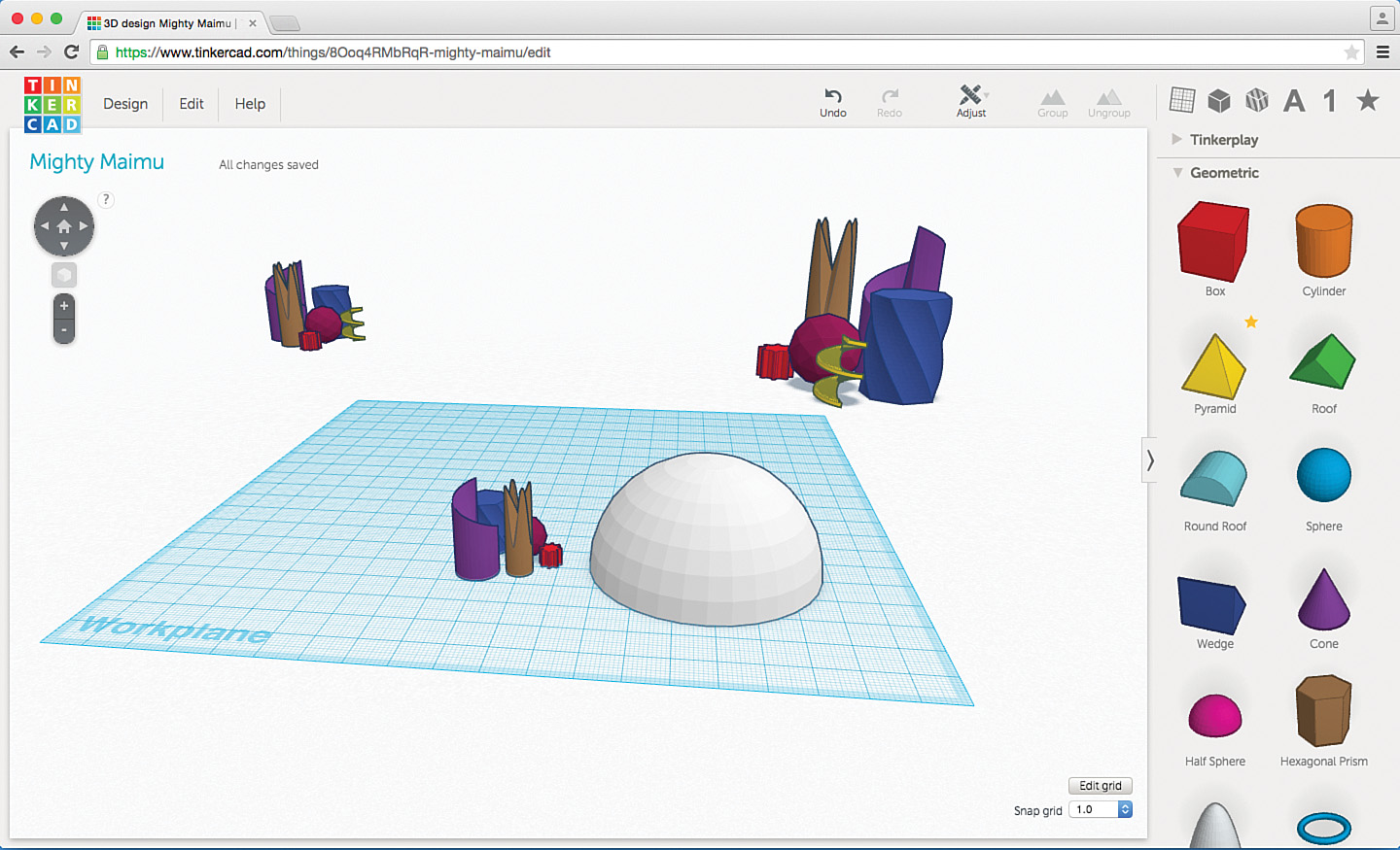
To start, make a bunch of copies of the city, as shown in Figure 11.23. You might want to shrink one and enlarge one so you have three different sizes as shown here.
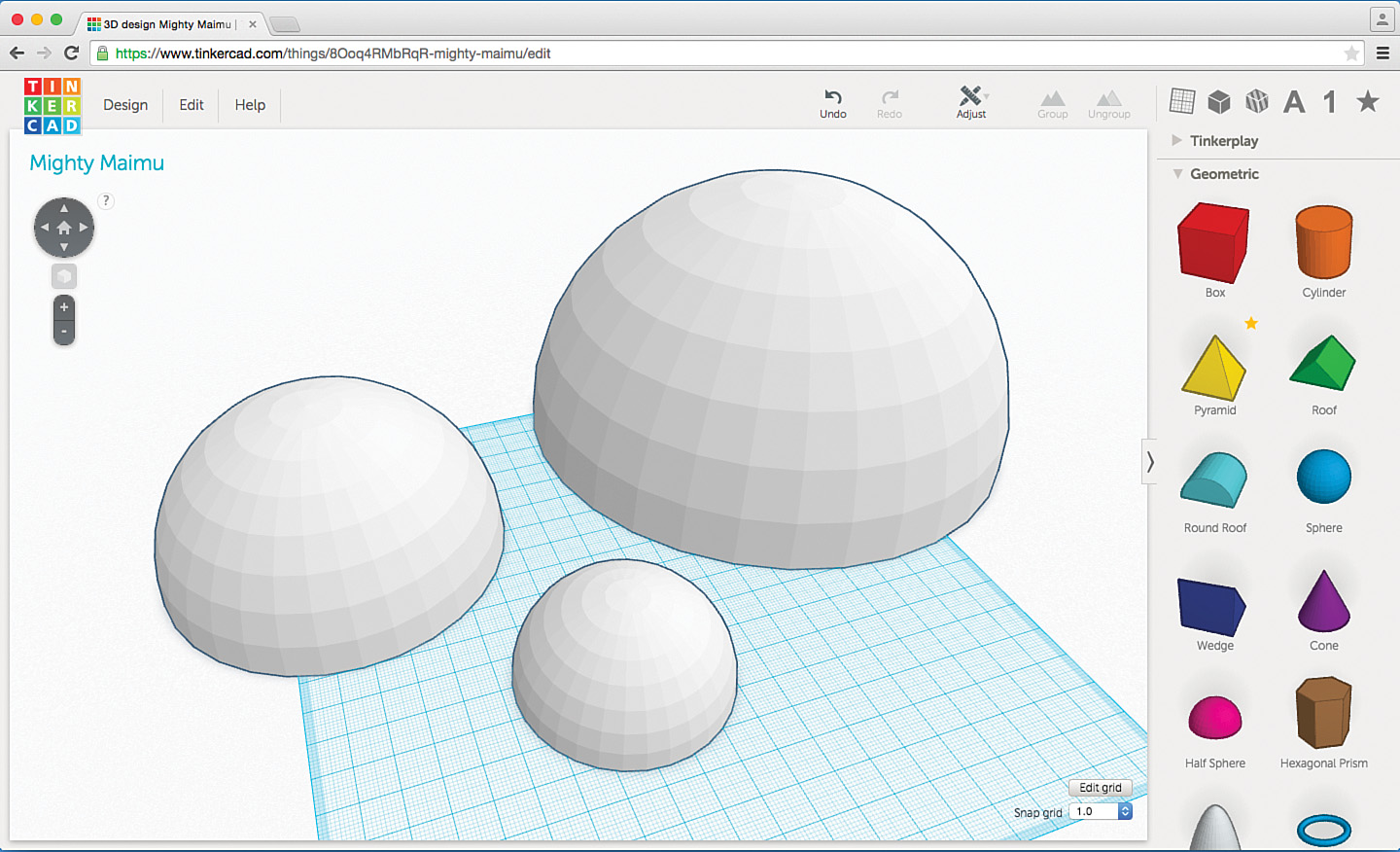
The plan is to cover these cities with domes. Domes are hollow, but all you’ve got to do to make one solid is use the Half Sphere object, shown dropped onto the workplane in Figure 11.24.
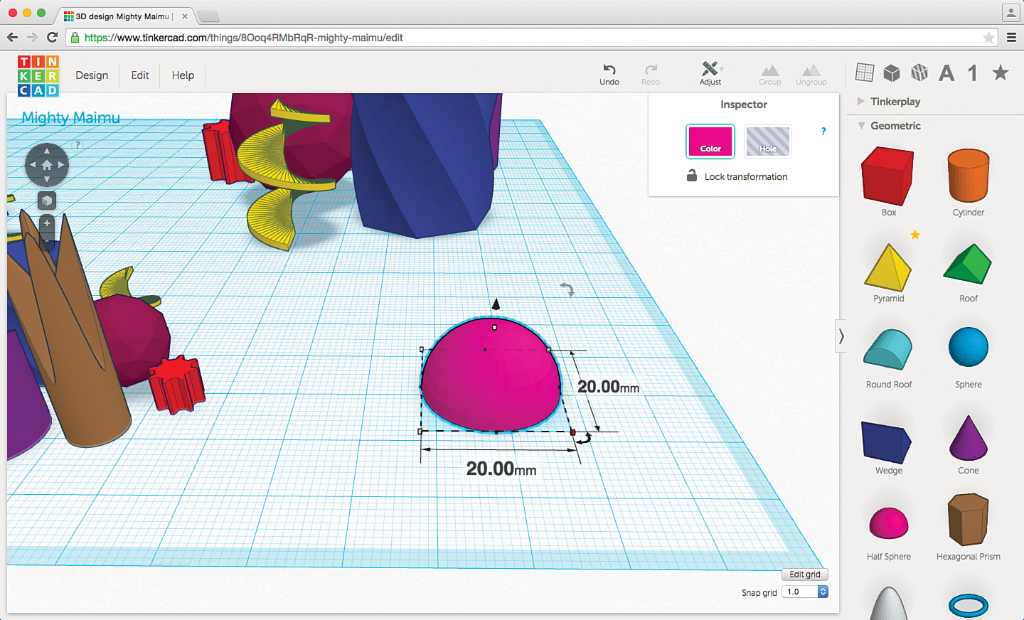
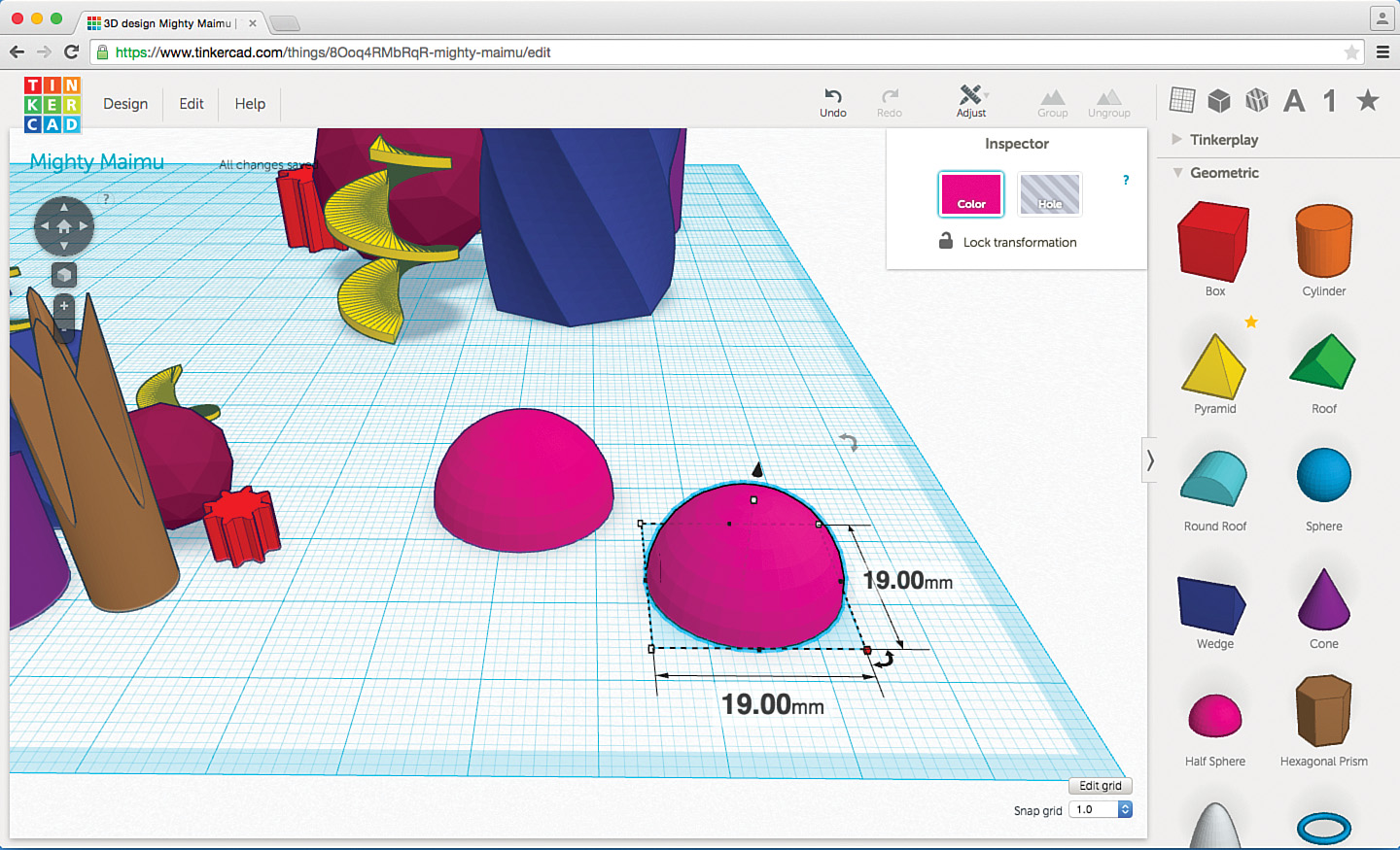
You need the domes to be extremely thin. This dome is 20mm in diameter and is solid. Making it 1mm thick (or 1 block in Minecraft) means hollowing it out so it has a 1mm thick shell. To do this, you need to create a copy of the dome and reduce it in size to 19mm. By holding down the Shift key while reducing the size, you can keep the perfect half-sphere shape, as shown in Figure 11.25.
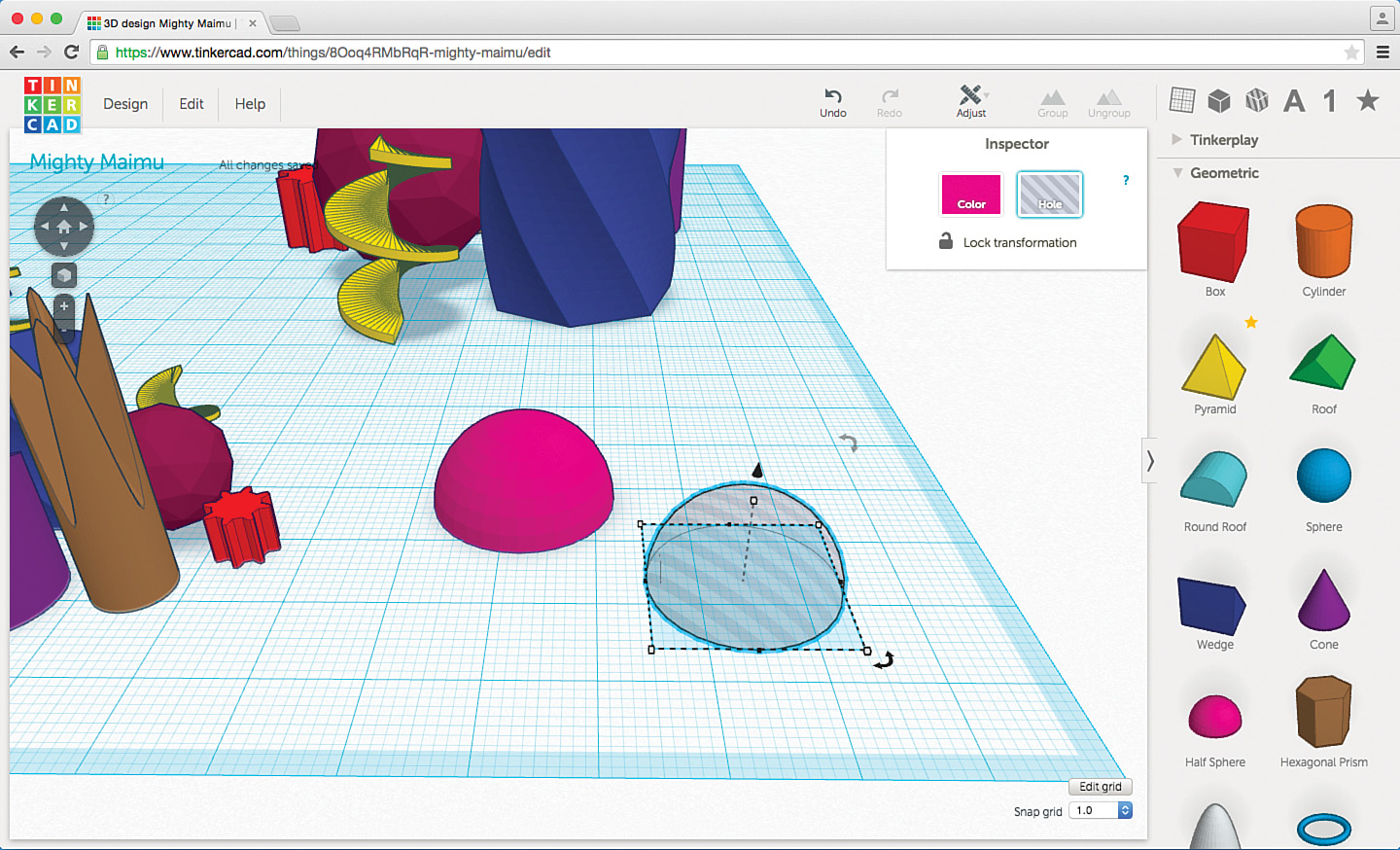
The next step is to make the 19mm diameter half sphere a Hole object, so select the 19mm half sphere and click the Hole button. You’re left with the “invisible” version shown in Figure 11.26.
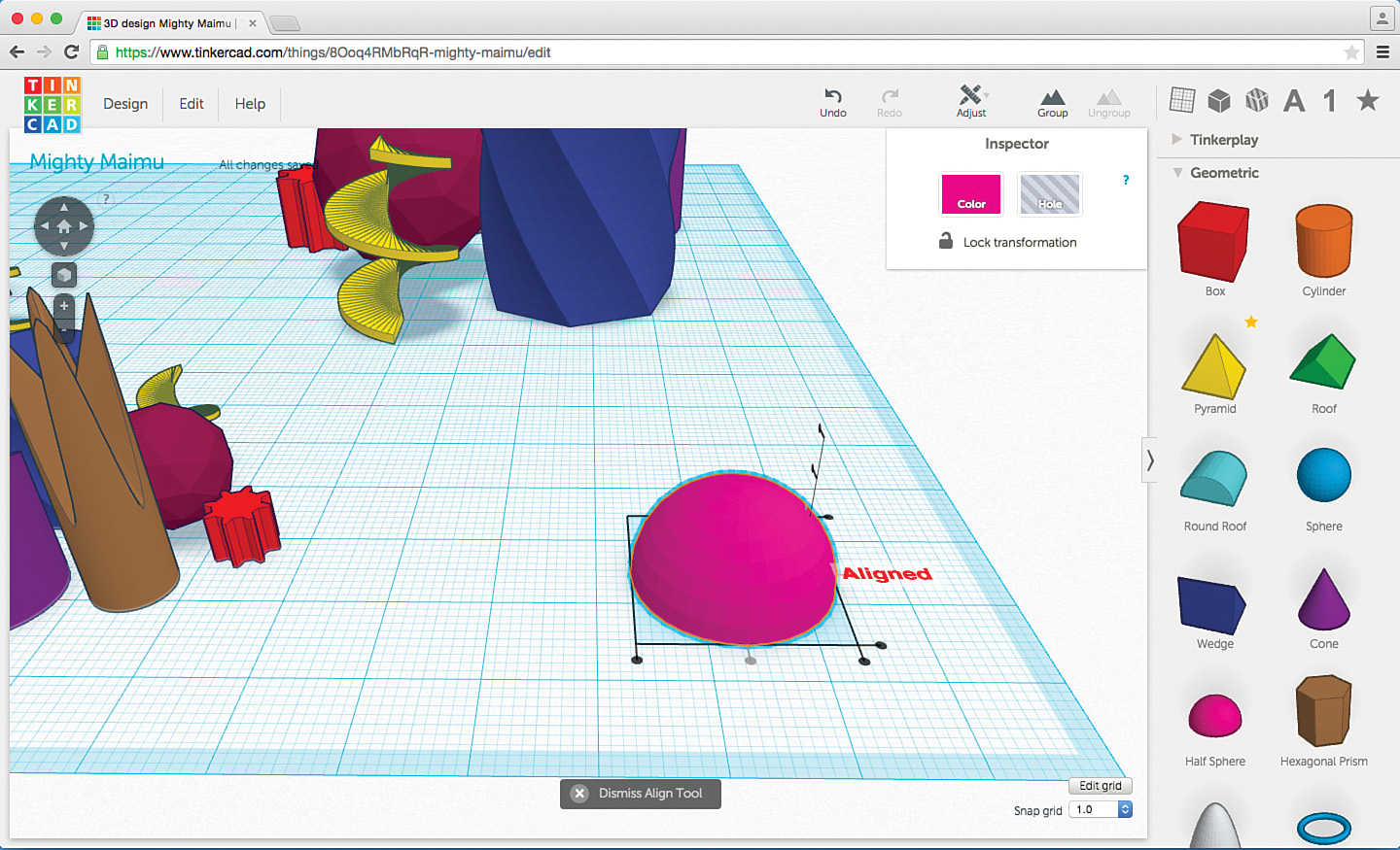
I’m hoping you can see why the Align tool you learned about in the previous section is so useful. Here, you’ll be using it to “stack” the solid half sphere on top of the Hole object half sphere and centering them on the X-axis and Y-axis. First, you merge them. In Figure 11.27 I’ve left a little of the Hole object visible so you can see that it’s “underneath” the solid version.

Then select both objects, click on the Adjust menu, and select Align. Next, click on the X-Axis Center dot and the Y-Axis Center dot. With the Hole object centered, it’s no longer visible in Figure 11.28.
Now group the two objects by using the Group button. Just by looking at the object, you can’t tell that the grouping is successful, but if you change the view by going “underneath” the workplane, you can see that the 20mm half sphere is indeed hollow, as shown in Figure 11.29.

You need to make three copies of this sphere (and change their sizes so they’ll fit over the three cities), but before you do that, you need to change the color of the half sphere to white, as shown in Figure 11.30. As mentioned earlier, choosing the color you want now will make it easier later, in MCEdit, to select only the Dome objects because they will be made of different materials than the cities. (Just make sure you don’t have any white buildings.)

Provide space between objects for proper dome placement
You might need to select each city and drag it out a bit so you can fit a dome over each one of them. Start with the smallest city first and then drag the other two cities further away if they touch the first dome.
You need to hold down Shift as you increase the size of the hollow half sphere so it’ll fit over the smallest city. You can see this in Figure 11.31.
Drag the half sphere dome over the city and then look from “underneath” the workplane, as shown in Figure 11.32. Drag the Dome so that the city isn’t touching any part of the dome.

Note
Don’t forget to group the city objects first
You might be wondering if you can use the Align tool to center the dome directly over the city. You can, but only if the city is grouped (and thus the same color). If the city isn’t grouped, when you align along the X-axis and Y-axis, all the various (ungrouped) buildings will be centered, too…causing them to all merge together and form one very strange-looking object. Try it if you need confirmation and then use the Undo button to return your city to its original layout.
Make two copies of the dome and enlarge them and place them over the remaining two cities. Once the domes are in place, you can select a city/dome pair and drag them so all three cities are close together (but not touching), as shown in Figure 11.33.
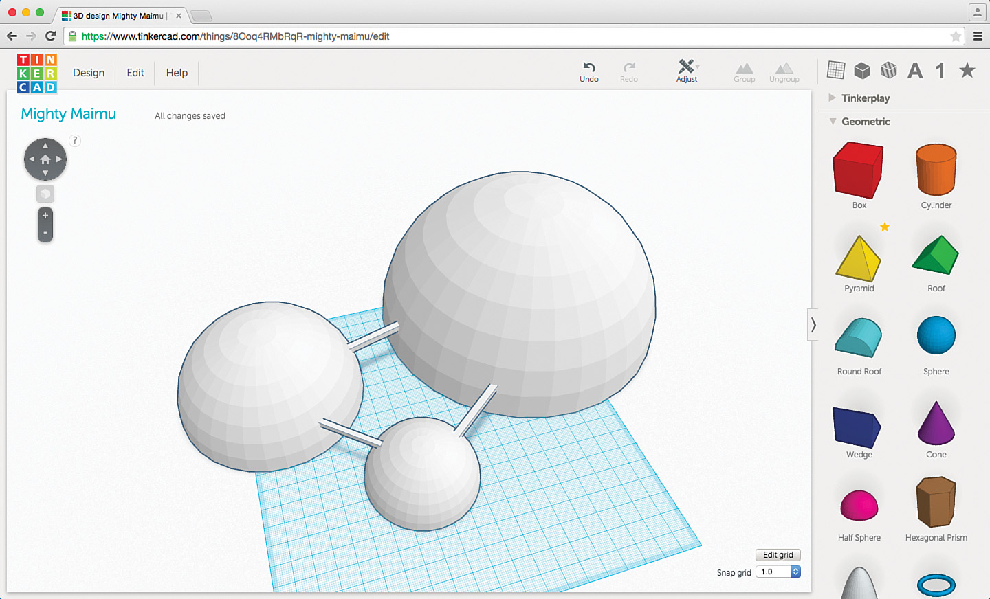
You can click the Design menu and choose Download for Minecraft to export your domed cities, but first you might consider adding some tunnels or walkways so you can travel from one dome to another without going outside the protection of the city domes. This isn’t difficult to do: Simply create three rectangular Box objects, make them hollow (shrink down a copy of the tunnel, make it a Hole object, and center it around all three axes inside the larger Box object before using the Group button), make them white, and then use the Black Cone and Rotate controls to place them so one Box object connects two domes. Figure 11.34 shows such walkways added.
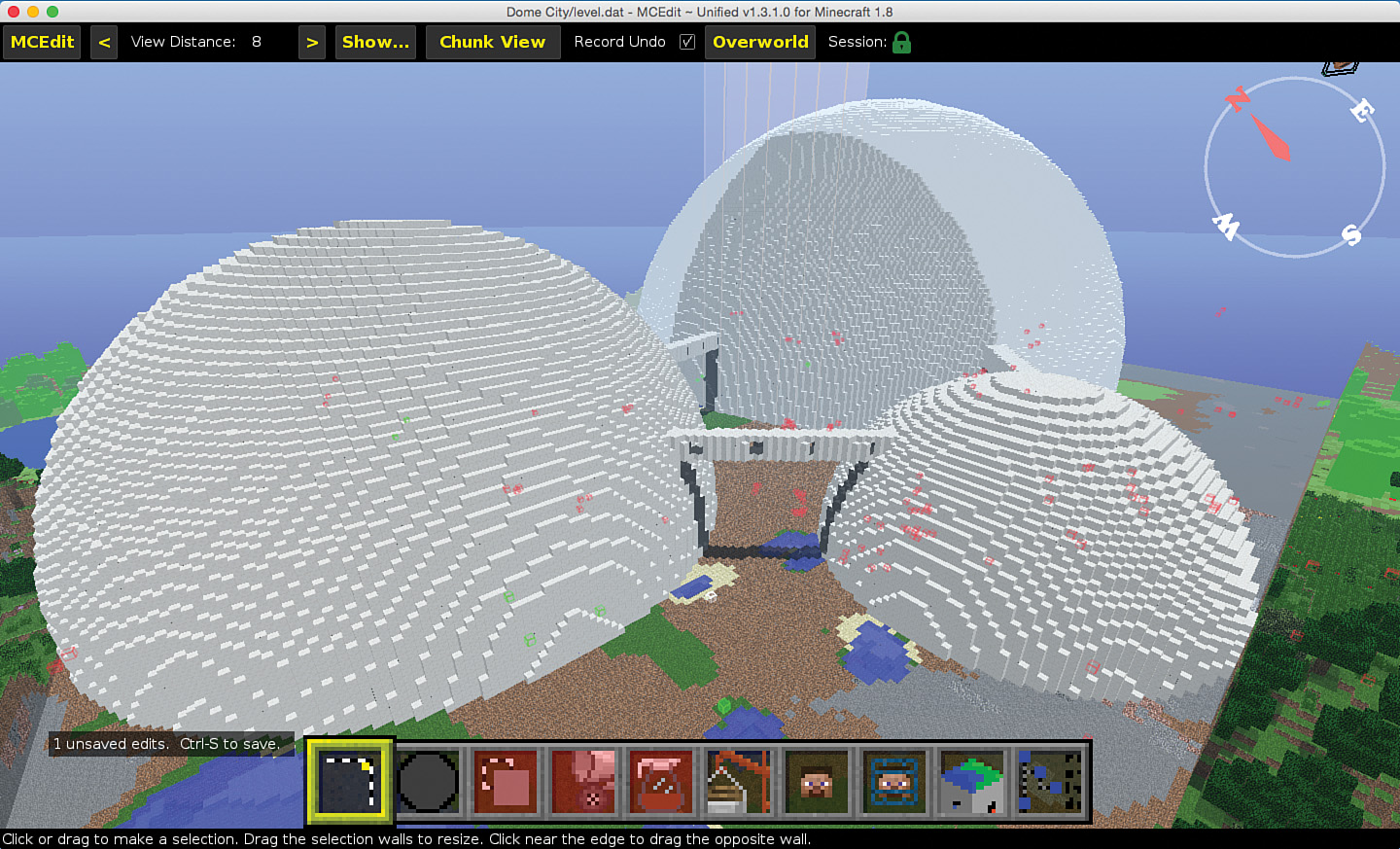
With the cities and domes created, all that’s left is to import them into a Minecraft world with MCEdit. You’ll need a very large piece of flat (or semi-flat) terrain to place the domes and cities, but if you don’t have that, you can always use MCEdit to clear away a nice plot of land. Take a look at Figure 11.35, where you can see that I’ve dropped the three domes into one of my worlds.
You could stop here, but the domes are solid, so they won’t let any sunlight or starlight in. You probably want to change that!
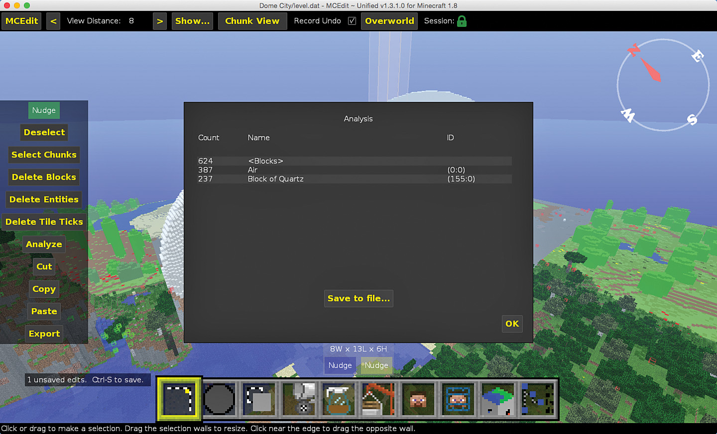
To start, you need to find out what material the white domes are made from. To do that, you can simply select a small bit of a dome (click on the Select button on the far left if it’s not already chosen). Click the Analyze button on the small window that appears on the left side of the screen, shown in Figure 11.36. An Analyze window appears in the center of the screen—here you can see that a bunch of air blocks and a bunch of quartz blocks are selected, so you know the domes are made of quartz!
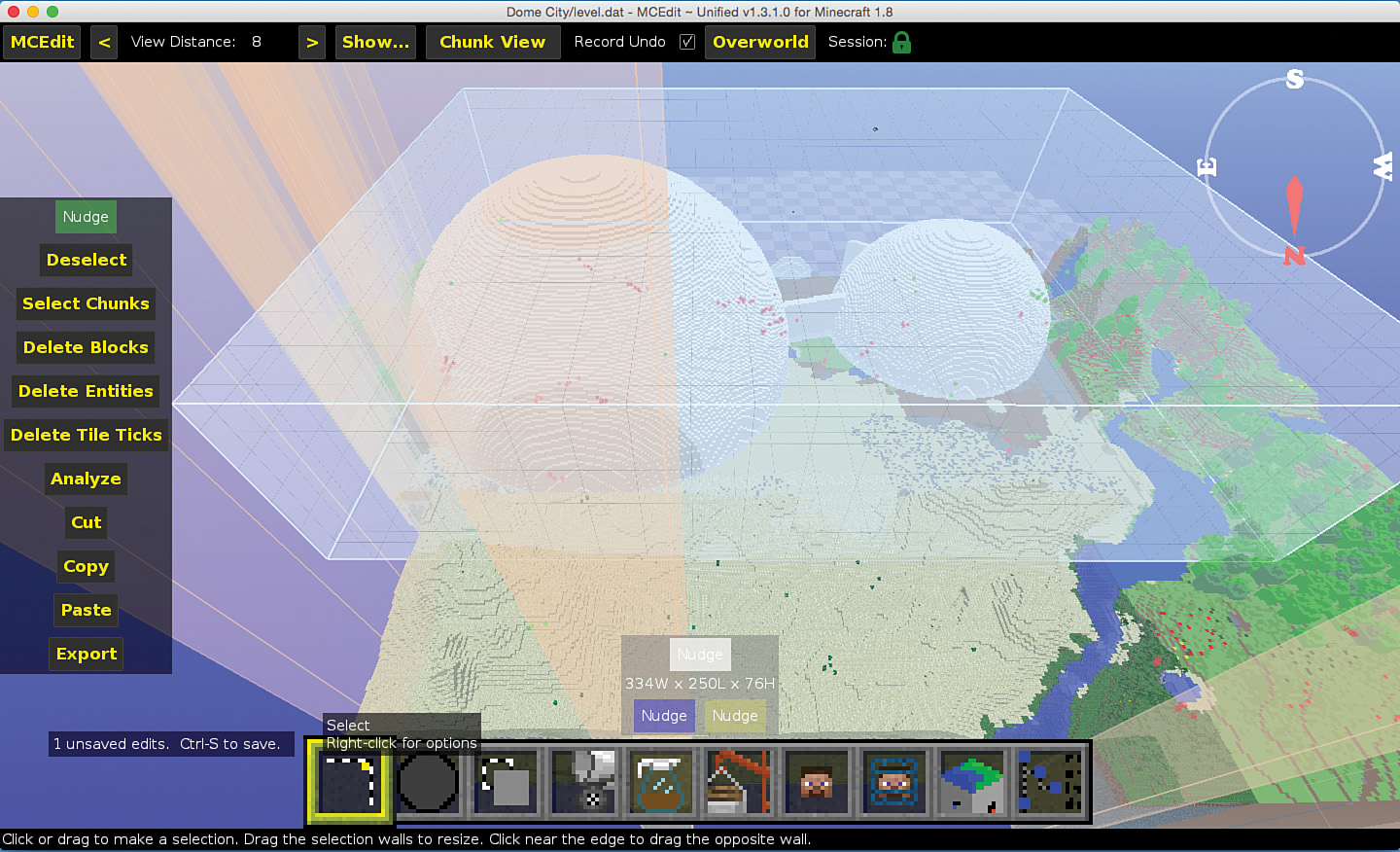
Next, use the Select tool again but this time select all three domes, as well as the walkways, as shown in Figure 11.37. Use the WASD keys to confirm that the selection box goes around all three domes.
Next, click on the Fill and Replace tool (fourth from the left), and the Fill With window appears on the left, as shown in Figure 11.38. Click on the Replace button.
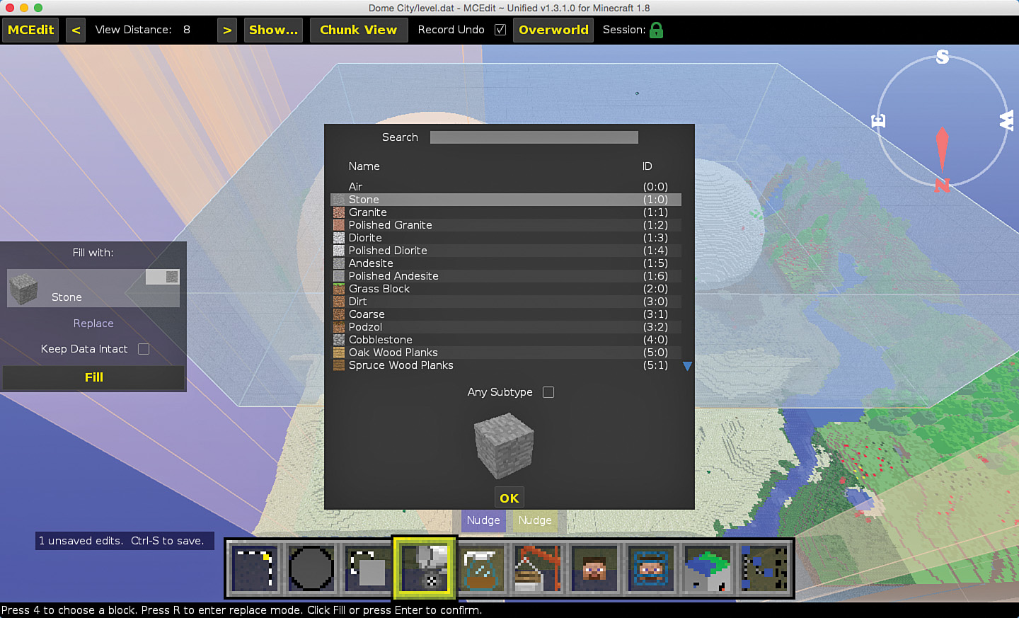
After clicking the Replace button, you get two options in the Fill With window: one is the material to search for and the other is the material to use instead of what’s already there. Start with the material to be replaced: Double-click on the Stone material in the Fill With window and type Quartz in the Search window in the center of the screen (see Figure 11.39).

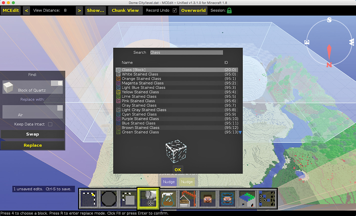
Click the OK button, and the quartz block appears in the Fill With window. Next, click on the material that appears in the Replace With section (the air block is the default), search for Glass in the Search window in the center of the screen (see Figure 11.40), and click the OK button.
Confirm your selections and click the yellow Replace button, as shown in Figure 11.41.

If your selections are accurate, you’ll end up with semi-transparent domes, as shown in Figure 11.42. But what will this look like inside an actual Minecraft world? To find out, save your changes, exit MCEdit, and open up the world in Minecraft.
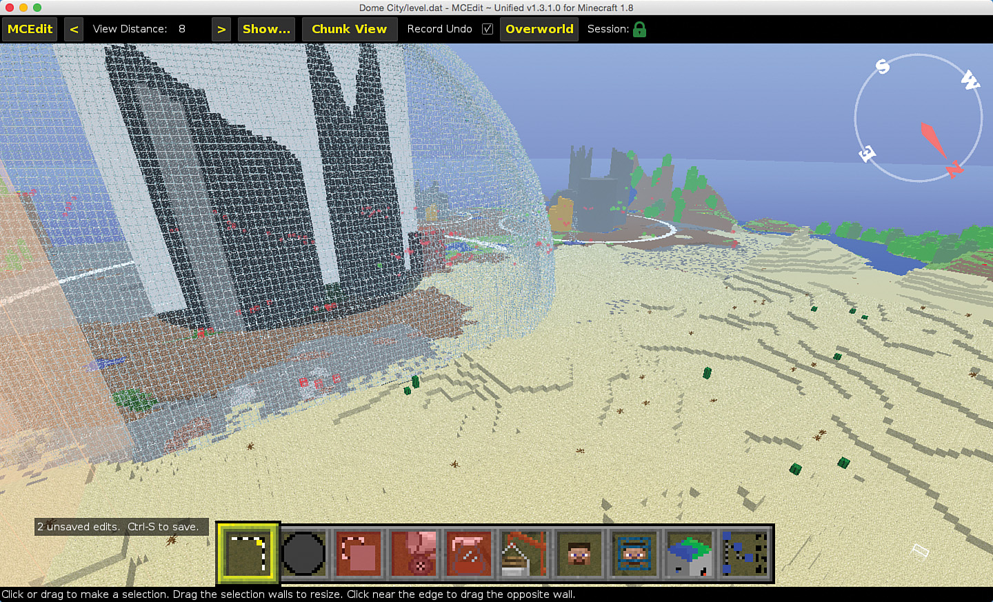
Figure 11.43 shows the final results. You can see the cities through the clear domes!

Of course, here you’re looking from outside the domes. You’ll need to break the glass to get inside and then seal up the hole. (Instead, you could move into a dome while you’re in MCEdit, and after you save the edit, you’ll find yourself inside the dome when you open up and play in the world.)
The creation of the domes and the cities inside may seem like a lot of work in Tinkercad, but consider for a moment how long it would take you to build those buildings and then construct the domes over them (and glass is fragile!) using block-by-block assembly inside Minecraft!
CAD applications such as Tinkercad are a secret Minecraft weapon. With them, you can make your ideas reality much more quickly and easily than you can by using the block-by-block building technique that most Minecraft users think they’re stuck with. And this means less time building and more time exploring and enjoying your creations.
Up Next…
You’ve finished up learning the most popular and useful Tinkercad tools and skills, but MCEdit has some additional features that you’re going to want to learn before you’re done with the book. In the next (and final) chapter, I’m going to show you a few final tricks that MCEDit offers to Minecraft engineers looking to push their building skills even further.