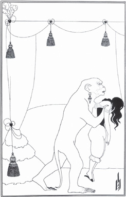
The Murders in the Rue Morgue, Aubrey Beardsley, Illustrations of short stories by Edgar Allan Poe, 1894-1895.
No matter the weight of the line, from finely etched crosshatching to bold marker or brush strokes, line art is binary: the color is either on the paper or it is not. Line art uses solid colors, and does not include a continuous tonal scale. A newspaper headline is line art, but the photograph below the headline is not line art. Lines and shapes form a composition with a strong figure/ground and negative/positive space interplay.
Line art as has routinely been employed in the commercial arena. (Fig 6.1) Andy Warhol blurred the border between the worlds of commercial and fine art by using line art and flat graphics on paintings to be shown in galleries and museums as a critique of the commercial world that this genre serves. Visible in Warhol’s illustrations of Campbell’s soup cans are thin, black lines that delineate the top edges of the can and a large, flat field of red-orange on the label.

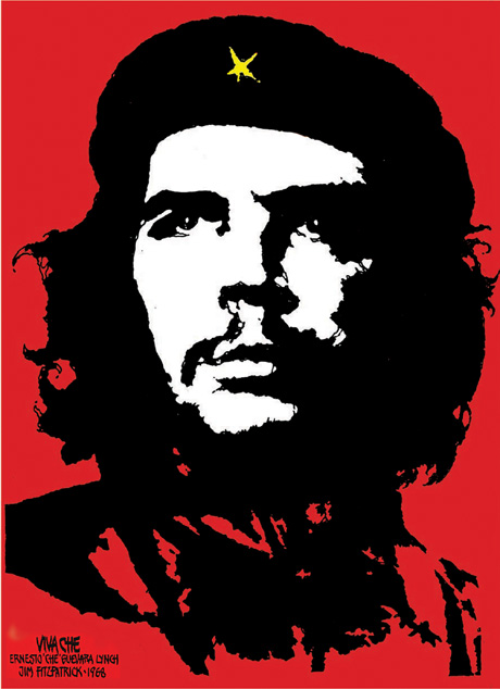
Plakatstil is the original flat graphic style used in advertising and poster campaigns. Plakatstil is German for “poster style.” Plakatstil is the opposite of decoration. Flat graphics are bold and minimal; often type is large. Lucian Bernhard’s 1906 poster design entry to a contest held in Berlin by the Priester Match Company is the first work to embrace this new graphic style. Bernhard was inspired by the industrialization of city life and a desire for rapid communication. In posters such as Bernhard’s, or Jim Fitzpatrick’s poster of Che Guevara, the color palette is minimal, and the contrast between shapes, values, and intensity is extreme. (Fig 6.2) As a result the message is bold and powerful.
Although line art and flat graphics are especially used for the commercial purposes of logo and identity pieces, the outcome of drawing a single line is as personal as your signature. Artists such as Pablo Picasso and Egon Schiele (see Chapter 1) are often identified by their line quality. Revisit Schiele’s work and notice that contrast can be achieved by juxtaposing solid and implied lines as well as lines of varying thicknesses.
The Pen tool is used for creating lines and shapes. It can be used to to draw or to trace images. In addition to contouring and tracing, the Pen tool is often used to create masks. Using this tool sometimes feels counter-intuitive. The artist has to know where her next point is before plotting it. The forethought that accompanies the use of this tool—visualizing lines, shapes, and space before they exist—can be challenging. In this exercise, you will make quick gesture drawings of lines and shapes with the Paintbrush tool and then recreate them accurately with the Pen tool. With enough practice on top of template layers, you are sure to develop Pen tool intuition.
Exercise 01: Gesture drawings on a template layer[*]
Start with a new Adobe Illustrator print document set to standard letter-size dimensions.
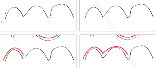
To begin, we will set up a template layer with quick gesture strokes using the Paintbrush tool. Select the Paintbrush tool from the Tools panel. Press the letter d on the keypad to set the default colors into the fill (white) and stroke (black). Draw a straight line by clicking and dragging with the Paintbrush tool. Deselect the straight line by clicking off of it with the Selection tool.
Draw a triangle with the Paintbrush tool. The results of the paintbrush drawings are vector shapes, which are outlined by anchor points that can be modified with the Direct Selection tool.
Deselect the triangle and draw the remaining curves pictured at right. (Fig 6.3)
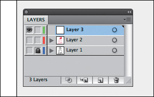
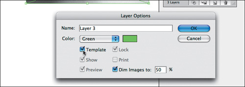
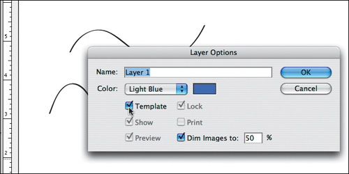
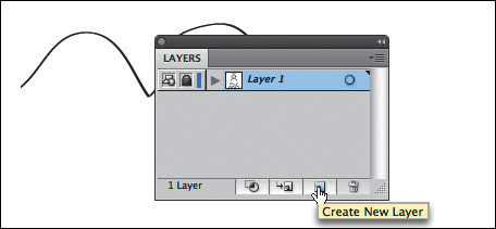
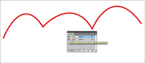
Open the Layers panel by clicking in the panel shown in the illustration below or choosing Window > Layers. Double-click the icon for Layer 1 in the Layers panel. Click the Template button and then click OK. The Template feature will lock the layer, so that you will not accidentally modify the paintbrush work. Template layers also dim artwork on those layers (this will be especially evident in Exercise 4). (Fig 6.4)
Create a new layer in the Layers panel. We will use the Pen tool on Layer 2. (Fig 6.5)

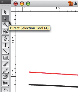
Select the Pen tool from the Tools panel. Click and hold your mouse on the tool to see the additional tools used on vector paths. (Fig 6.6)
The Pen tool plots anchor points each time you click the mouse. Click once on the Stroke icon at the bottom of the Tools panel and set the stroke to red, so that you will see your work when it sits on top of the black template layer. Set the fill color to none.
To make a straight line in red, click one time at the beginning of the black painted line. Release the mouse. Move the mouse to the end of the black line. Click one time. In two clicks, the Pen tool creates two anchor points and joins the points with a straight line. (Fig 6.7)
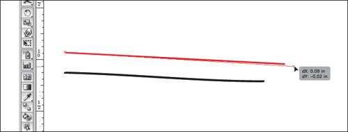
Once the line is made, it can be modified with the Selection tool for moving, rotating, or transforming or by the Direct Selection tool, to modify one anchor point at a time. (Fig 6.8) Deselect the line, then use the Direct Selection tool to click once on the anchor point at the end of the line and drag it to increase the length of the line. (Fig 6.9)
Use the Selection tool to select the line and change the weight of the stroke from the Control panel. Notice how the line can be bold and aggressive with a larger stroke size, or slim and faint with a stroke size that is less than 1 point. Deselect the line when you are finished.


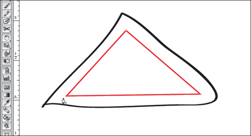
Click once at one corner of the triangle with the Pen tool. Release the mouse. Click on the next corner of the triangle. Release the mouse. Click on the third corner of the triangle. Release the mouse. The fourth click needs to be exactly where the first anchor point was made. (Fig 6.10)
Notice in this image that the Pen tool displays a small circle, symbolizing that the path will be closed and a whole object is made when the last click is made directly on the first anchor point. This is referred to as closing the path. When a path is closed, or a shape is whole, it is easy to fill the shape with a color using the Selection tool and the color tool panels. If the shape is not correctly closed, the entire Artboard will be filled.
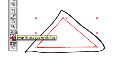
Select the triangle with the Selection tool if it isn’t already selected. Click the curved arrow above the Fill and Stroke tools in the Tools panel. The stroke and fill colors switch places. (In this example, the triangle becomes red with no stroke, as opposed to a triangle with no fill, outlined in red.) (Fig 6.11-12)

Just for practice, use the Direct Selection tool to modify two anchor points at a time. You can also click on one side of the shape with the Direct Selection tool and modify a side. Click on one anchor point of the triangle. Hold the shift key and click a second anchor point (so one whole side is selected), then begin dragging the mouse to move both anchor points at one time. Alternatively, you can marquee over one side of the triangle, and two anchor points will be selected. You can click and drag with the mouse to move these anchor points, or you can use the up, down, left, and right arrows on the keypad.
Shift+Arrow modifies the placement by 10 pixels.
Begin by creating a second shape (a parallelogram) using the Pen tool. Plot the first anchor point near the top of the first triangle.
Use the edge of the first triangle to help visualize the dimensionality of the second shape. Plot the second anchor point to create a parallel line between the two shapes.
Set the third anchor point so the area appears to recede in space, creating a unified perspective between the two shapes.
Close the path by using your fourth mouse click to return to the first anchor point. If the shape isn’t perfect, you can always go back with the Direct Selection tool to modify individual anchor points. (Fig 6.13)

Stand outside early in the morning or at twilight and look far down the street towards the horizon. Objects that are further away appear less saturated than those that are near. Atmospheric perspective accounts for the perceptual change that happens to the overall opacity of objects as they recede in space.
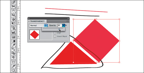
Select the parallelogram and fill it with the same color you used in the triangle.
Open the Transparency panel (Window > Transparency). While the second triangle is still selected, change the transparency to 80 percent. Flat, basic shapes created with the Pen tool can be combined to imply complicated shapes and three-dimensional space by using different transparencies to create a sense of atmospheric perspective. (Fig 6.14)
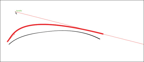
The first curve is created in two points. The first anchor point is made by clicking and dragging the mouse slightly upward to imply the direction of the curve. Do not drag all the way over the curve as if you are using a pencil or paintbrush; this tool does not work like a pencil or paintbrush. Release the mouse. (Fig 6.15)
Click once at the end of the curve and drag slightly downward until the curve looks similar to the template. (Fig 6.16)
Deselect the curve.

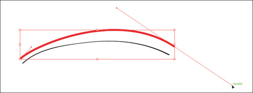
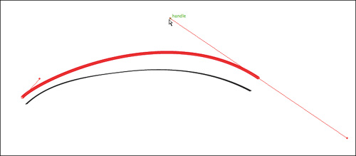
When you are finished, you will have one curve with two anchor points. Each anchor point will also have bezier handles, which are used to modify sections of the curved line. With the Direct Selection tool you can modify the anchor points, the line segments, and each bezier handle. Every curve has a mid-way point—the bezier handles pull on each side of this point. (Fig 6.17-18)
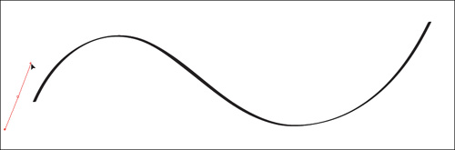
Click and drag with the Pen tool in the direction of the first curve. Release the mouse. (Fig 6.19)
Click at the end of the first curve and drag down with the mouse—this tells the Pen tool the direction of the next curve. Release the mouse. (Fig 6.20)
Click at the end point of the last curve and the final curve is made between the last two anchor points. (Fig 6.21)
When you are working with the Pen tool, you have to think ahead of the tool, towards the place where the line changes. Think about where the curve should change directions. This will inform where you click and how you drag the mouse.

You can click on an anchor point with the Direct Selection tool and press the Delete key, or, if the anchor is in the middle of a path, you can use the Subtract Anchor Point tool (Pen Minus) to click on an anchor point you want to delete. You can use the Add Anchor Point tool (Pen Plus) to add an anchor point anywhere on a path after you have finished creating it. (Fig 6.22-23)

Deselect before working on the next exercise.
The last sample on the template is an example of a curve next to an angle, next to a curve, next to an angle, and so on. The Convert Anchor Point tool is used to create this juxtaposition. This tool becomes active if you place your mouse near an anchor point while drawing a path. It is also available as a separate tool, hidden beneath the Pen tool in the Tools panel.
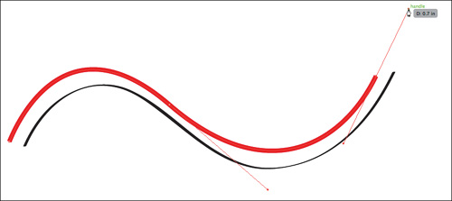
Use the Pen tool to click once and drag in the direction of the curve at the first anchor point.
Click at the second anchor point and drag to finish the first curve.
Now place the Pen tool close to the anchor point you just created, wait until you see the Convert Anchor Point tool, then click the mouse. The bezier handle disappears because you no longer have a curve. The Convert Anchor Point tool can be used to convert an anchor point from an angle to a curve or from a curve to an angle. (Fig 6.23)
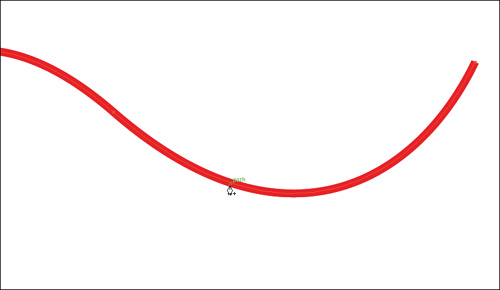
Click after the next curve and drag the mouse down to create the curve.
Click on the anchor point to convert it to an angle.
Repeat this process until you trace the template. (Fig 6.24)
By understanding how to create straight lines and curves, and by converting anchor points from curves to angles or angles to curves, you can trace any image.

The Pen tool is often used in combination with images or vector art to create clipping masks. A mask is used to define which parts of an object or image are revealed to the viewer. They are commonly used on photographic images to hide the background around a figure in the image. A good example of this is a magazine cover or advertisement where the background is completely solid. Alpha channels, layer masks, and clipping masks can be made in Photoshop. We will create masks in Photoshop in Chapters 10 and 11. In this exercise, we will use the Pen tool to create a clipping mask. The Pen tool can be used to mask an object or image in InDesign and Flash, as well. For this exercise, place any image onto the template layer and trace it with the Pen tool on Layer 2. An image of a human figure is a challenge, as it always includes combinations of curves and straight lines. Included on the wiki is a photograph of a hand in front of a flat wall. You can do this exercise using that file or any image of your choice. First the Pen tool will be used to draw a path around the arm, then the resultant path will be turned into a clipping mask to hide the rest of the photograph.
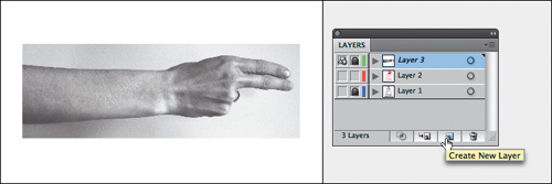
Create a new layer and turn off the Eyeball icons of the other two layers to hide them while you are working on this new exercise. (Fig 6.26)
Choose File > Place to place the image of the hand (or your image) on the new layer.
Watch Out
The Link checkbox in the Place dialog box is used to link (when checked) or embed (when unchecked) the picture file in the Illustrator document. Linked files are not actually stored in the Illustrator document, so the file size of the Illustrator document is not affected by large images. However, linked files must remain available on the hard disk in the same relative position as they were when the relationship between the linked image and Illustrator file was established. If you are unsure what that means, keep Link unchecked and let Illustrator embed the image file.
Double-click the icon in the Layer panel and click on the Template checkbox. The image will appear dim. Create a new layer above the template layer. (Fig 6.27-28)
Use the Pen tool to trace the contour of the image. Remember to start and stop on the same anchor point. Also remember that the path doesn’t have to be perfect, as the Direct Selection tool can be used to modify it once it has been created. (Fig 6.29)
To transform the path into a clipping mask, you will select both the path and the image. First, unlock the template layer. Use the Selection tool to click on the path first, then hold Shift and click on the photograph. You will see anchor points around the path you just plotted and on the four corners of the placed photograph. Choose Object > Clipping Mask > Make. (Fig 6.30)
Tip
The path that will become the clipping mask should be inside the boundaries of the photographic image. That is, the photographic image should be larger than the path that will be used to mask it. If the path is larger than the entire image, the mask will simply reveal everything, in which case there is no reason to use a mask.
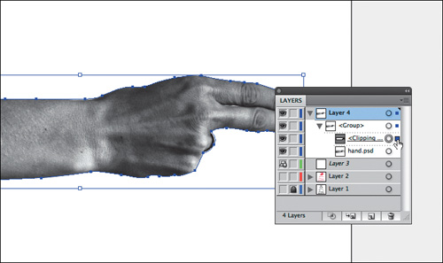
Modifying the clipping mask or image that is masked is possible, as long as you select just one or the other with the Direct Selection tool. This is not always as easy as it sounds. The most fool-proof way to select the mask and not the image is to use the Layers panel. Expand Layer 2 by clicking on the arrow left of the small thumbnail on the Layers panel. Now you have a group that contains the clipping mask and the photographic image. You can see the mask and the image as separate parts of the layer. (Fig 6.31) A small colored box appears in an area on the right of each path on a layer when that path is selected. Clicking on this area when it is empty will select a path. Click this area of the Layers panel on the clipping mask layer. You will see a blue box in the Layers panel and the anchor points surrounding the mask within the document. Use the Direct Selection tool to modify the mask without altering the photographic image.
The Selection tool can be used to move the entire image and mask as one unit, since they are grouped together within the Layers panel. Once a clipping mask has been made, it will remain grouped in the Layers panel unless you release it.
To delete the clipping mask, click on it with the Selection tool then choose Object > Clipping Mask > Release. Now both the path that was used as the mask and the image are available as two separate objects. They can be deleted or modified as individual objects. (Fig 6.32)