The single most important determinant of the quality of a software system is its architecture. A good architecture keeps concerns of different kinds separate so that a change in one does not affect other parts of the system. You establish this architecture by identifying the critical use cases for the system. By analyzing these critical use cases, you can build a resilient structure—one in which concerns of different kinds are kept separate and changes in one part of the system have minimum impact on the rest of the system. The architecture must also be designed to meet system-level concerns such as performance and reliability. The architecture is manifested in an early and critical version of the system, a version that can be made executable—a version we call the architecture baseline. It might take several iterations before you finally establish the architecture baseline, but when you do, you have validated your assumptions, your approach to developing the system, and you have reduced your risks. Based on this architecture, the rest of the development can speed up tremendously.
Architecture clearly is important, but if you ask five different people what architecture really is, you will probably get five different answers. Architecture, like many other words, is something you cannot really touch. It is in that sense similar to process, use case, project, component. However, these terms are concrete in the form of their descriptions. We can understand a process description, a component description, a use case specification, a project plan and, thus, an architecture description. So, when we talk about architecture, we talk about how we understand the architecture description. Architecture is thus the semantics of an architecture description, which encompasses the major decisions about the system, such as:
How are the system elements organized?
How does the system realize the required functionality?
How does the system meet the desired performance, reliability, and other quality characteristics?
What technologies does the system require (e.g., Web client, rich client, a particular messaging middleware)?
Are the internals of the system structured to be resilient to changes in functionality, technology, platform, and so on?
Are standards in place to ensure that the system is developed consistently? For example, what design patterns will be used? What guidelines will be used to handle exceptions?
Definitely, there are important, project-specific decisions to consider. For example, you may have to interface to a particular legacy system. Or maybe the system has to be configurable and you need a way to define system parameters. Perhaps the system has to be remotely installed and managed. Possibly the system is to deal with the complexities of a particular business domain. The list goes on. But the architecture is not everything. It is just the top 20 percent of the most important things about the system.
So, a good architecture is important. But what constitutes a good architecture? Of course, a good architecture meets systemwide concerns such as performance and reliability. It must be understandable so that you can easily trace which part of the architecture realizes which requirement or use case. Each class—and consequently the packages it resides in—plays clearly defined roles and performs a set of responsibilities that fulfill those roles and nothing else. There is little or no duplication of responsibilities between classes.
A good architecture keeps concerns separate, which means that changes in one part of the system do not propagate to other parts of the system. Even if they do, you can clearly identify what changes are to be made. If there is a need to extend the architecture, the impact should be minimal. Everything that already works should continue to work. For a system that applies aspect orientation, the different concerns about a system can be kept separated effectively.
In general, you want to keep functional requirements, whether expressed as features, use cases, or in other terms, separate from each other. After all, they address different end-user concerns and will evolve separately. You do not want changes in one to impact the other. The functional requirements are often expressed on top of the problem domain (e.g., hotel management, logistics, banking, insurance, etc.). You naturally want to keep what is specific to the functionality of the system separate from the domain. In this way, you can easily adapt a system to a similar domain. In addition, some functional requirements are defined as extensions of other functional requirements: you must keep these separate from each other as well.
Nonfunctional requirements usually specify the desired quality attributes of the system: security, performance, reliability, and so forth. These are provided by some infrastructure mechanisms—for example, you need some authorization, authentication, and encryption mechanisms to achieve security; you need caching and load-balancing to achieve performance. Frequently, these infrastructure mechanisms require small bits of behavior that must be executed within many classes. This means that a change in the realization of an infrastructure mechanism often implies huge repercussions, so you want to keep these separate.
Today’s systems need to execute on top of many technologies. Even for a single infrastructure mechanism such as authorization, you still have many technologies (e.g., through HTTP cookies, session identifiers, etc.) to choose from. These technologies are often platform- and vendor-specific. When a vendor upgrades its technologies to a new and better version, it is not easy to upgrade your system accordingly if your implementation has been tightly coupled with the previous version of that technology. You most certainly do not want to be tied down to a particular technology. Thus, you need to keep platform specifics separate.
As part of implementing a test, you must perform some control and instrumentation (e.g., debugging, tracing, logging, etc.). Control is for the purpose of forcing the execution flow of the system to follow some test sequences. Instrumentation is for the purpose of extracting information to verify that the system does indeed follow the desired test sequence. Control and instrumentation usually require some behavior that must execute within the context of the system under test. Such control and instrumentation behavior have to be removed after the test is conducted. Thus, you want to keep the implementation of tests separate from the system under test.
A good architecture should be established as early as possible. Even in theory, it is very difficult to change a poor architecture into a good one with incremental techniques such as refactoring. In practice, it is extremely difficult. This is not to say that refactoring is not useful, but it is much better to begin with an initial structure that is relatively good. Otherwise, the cost of refactoring is too high for any business-oriented manager to accept, and he or she will typically opt for quick fixes instead. So, a good architecture needs to be created when the cost of creating it is small or even non-existent. Prioritization of architectural work has a good return on investment. It reduces the need for redesign and minimizes throwaway work during the remainder of the project. Having achieved a good initial structure, you can continually evaluate the architecture and make the necessary refinements and refactorings.
The architecture is manifested as an early version of the final system known as an architecture baseline. The architecture baseline is a subset of the entire system, so we call it the skinny system. This skinny system has versions of all the models that the full-fledged system has at the end of the project. It includes the same skeleton of subsystems, components, and nodes, but not all the musculature is in place. However, they do have behavior, and they are executable code. The skinny system evolves to become the full-fledged system, perhaps with some minor changes to the structure and behavior. The changes are minor because, at the end of the elaboration or architectural iterations, we have by definition a stable architecture; otherwise, the elaboration phase must continue until we know that this goal has been achieved. There is a systematic way to do this.
Even though the skinny system (the architecture baseline) usually only includes 5 to 15 percent of the final code, it is enough to validate the key decisions you have made. More importantly, you need to be assured that the skinny system can grow to become the complete system. The skinny system is accompanied by a paper product called the architecture description. But now, this paper product is verified and validated through the architecture baseline.
The establishment of the architecture baseline is driven by a critical subset of use cases. We call this subset the architecturally significant use cases. Before you can identify the architecturally significant use cases, you must first identify all the use cases for the system—at least to the best of your knowledge with the available information. Please note that identifying use cases is not the same as specifying use cases. Identifying is about scoping and exploring and finding what the system needs to do. Specifying use cases is about detailing the flows and the steps in the use case. Specifying use cases is allocated across the project lifecycle. However, identifying the use cases can and must be done early.
From these identified use cases, you determine which among them are important—important in the sense that together they cover all the key decisions you need to make:
They exercise key functionalities and characteristics of the system.
They have a large coverage in terms of the various risks that you face concerning functionality, infrastructure, platform specifics, and so on.
They stress some delicate or risky parts of the system.
They are the basis for the rest of the system to be developed.
Architecturally significant use cases involve use cases of different kinds. After all, each use case captures a different set of stakeholder concerns and requires different decisions to be made. Your list of architecturally significant use cases will therefore involve a combination of both application and infrastructure use cases. You might find this in your system use cases that are technically similar and have similar interaction patterns. In that circumstance, you need to choose just one use case as a representative, since the moment you can solve one of them, you can solve the others. For example, the Check In Customer and Check Out Customer use cases are similar, so you choose just one of them to serve as an architecturally significant use case.
Once you have identified the architecturally significant use cases, you can explore the critical scenarios within them. As you analyze the use case scenarios, you get a better understanding of what the system needs to do and how the elements in the system should interact with each other. Through that understanding, you define and evaluate the architecture. This proceeds iteratively until you achieve a stable architecture. By stable, we mean that key risks in the system have been resolved, and the decisions made are a sufficient basis for you to develop the rest of the system.
The architecture is influenced not only by the architecturally significant use cases, but also by the platform, legacy systems that the system needs to be integrated to, standards and policies, distribution needs, middleware and frameworks used, and so on. Even then, use cases are still useful for evaluating the architecture. You analyze each use case in the context of the chosen platform, the chosen middleware, the chosen distribution structure, and so on. In this way, you can evaluate whether the choices you have made are sufficient and discover where improvements need to be made.
For a complex system, it takes several iterations before you finally establish a stable architecture. Since these iterations focus on developing the architecture, they are also called the architectural iterations. In Unified Process terminology, these iterations are known as elaboration iterations.
You must address all architectural concerns in each architectural iteration. You may not be successful at resolving all of them in each architectural iteration, but you need to consider all of them. Each architectural iteration produces an increment that resolves some of these architectural concerns.
The iterations proceed until all architectural concerns have indeed been resolved. At the end of these architectural iterations, you have an early version of the system (a skinny system) that is executable. It is supported by test and execution results, so it is verified and validated.
The version of the system at this point is the architecture baseline. Thus, the architecture is an early version of the system that demonstrates how architectural concerns are resolved. Since the system comprises a set of models, the architecture baseline is also represented by a version of these models. The architecture baseline is accompanied by an architecture description, which is an extract of the models.
The architecture description serves as a guide for the whole development team through the lifetime of the system. The architecture description is the reference to be followed by the developers in subsequent iterations of the project.
The architecture description is also reviewed by stakeholders to determine if the architecture is indeed feasible. Attached to the architecture description (and basically to every artifact) is a history sheet that explains the system’s evolution. It may also explain important decisions.
You normally find the architecture description developed concurrently, often ahead of the activities that result in the versions of the models that are parts of the architecture baseline. It is to be updated in iterations following the architecture baseline.
During architectural iterations, progress is relatively slow because you need time to make decisions. Once you have gone past the architectural iterations, productivity will shoot up significantly, so the time devoted to iterations is well spent.
Before we discuss architecture description, we need to present the concepts that will help you understand it. Since the architecture description is such an important artifact, we devote an entire chapter to it (see Chapter 18, “Describing the Architecture”).
The way you structure the system is an important architectural decision. You structure the system such that concerns are kept separate. You achieve this structure first from a platform-independent perspective and then refine it with platform specifics. A platform-independent structure is driven by functional requirements (as modeled with use cases).
The tools you use to achieve a resilient structure are classes and use cases. Classes help you keep the elements in a system separate, and use cases help you keep the tasks of each element separate. Accordingly, there are two orthogonal structures in the system—the element structure and the use case structure.
The element structure identifies where elements of the system are located in the element namespace. It structures the elements hierarchically in terms of layers, packages, classes, and the features within these classes.
The use case structure defines how you overlay functionality onto the element structure. It comprises slices—both use-case slices and non-use-case-specific slices—that add the actual classes and class features onto the element structure.
You want your structure to be resilient along both structures. This means that if there are changes in requirements, their impact should be localized to a few packages and classes in the element structure. Their impact must also be localized to a few use-case slices. Localized means that there are few changes, and the changes do not propagate beyond those packages or use-case slices that require change.
The element structure for a model is a hierarchical structure of packages and classes. It uniquely identifies each element. Since the goal is to achieve resilient structure, you naturally locate classes that are used for the same purpose together.
You normally use layers as the first-level partitioning in a model. Layers are used to group software elements that are on the same level of abstraction. You place more abstract and reusable elements in lower layers and more concrete or less reusable elements at the top. Normally, two high-level layers are sufficient to refine the functional requirements for the system: the application layer and the domain layer.
The application layer contains elements that realize workflows in the use cases supporting the primary actors of the system. The elements in this layer normally use the elements in the domain layer to realize use cases. You can organize packages in the application layer according to the following criteria.
Classes that support one or more particular actors.
Classes that are involved in one or more particular use cases.
Classes that are involved in some functional area in the system.
The domain layer contains elements representing significant domain concepts. They capture information to be maintained, tracked, or manipulated by the system and the associated behaviors for doing so. These elements are normally shared across use case realizations. They are more reusable and so reside in a lower layer than the application layer. However, since they are shared by use-case realizations, use-case realizations frequently cut across domain elements.
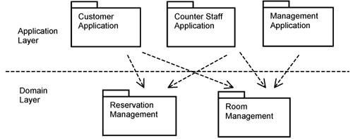
Figure 11-1 depicts the initial structure of the Hotel Management System that realizes the functional requirements of the system. The packages in the application layer are grouped according to actors—the customer, the hotel counter staff, and the management. The packages in the domain layer group classes related to rooms and classes related to reservations.
The structure in Figure 11-1 is an initial one. It is refined further into classes and so forth as you analyze the use cases for the system.
As mentioned, the element structure is simply about identifying elements in a namespace. It is the slices in the use-case structure that overlay the actual content for each element. There are two kinds of slices: use-case slices and non-use-case-specific slices.
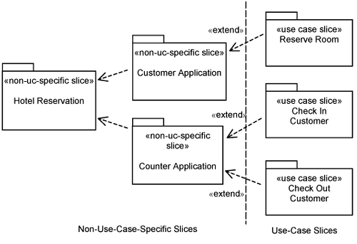
The convention is to depict the element structure (comprising layers, packages, and classes) vertically such that at the top you find application-specific layers and packages, and at the bottom you find application-independent ones (as per Figure 11-1). To emphasize the orthogonality of the use case structure, we depict the use case structure horizontally with the non-use-case-specific slices on the left and the use-case–specific slices on the right (see Figure 11-2). The arrows in Figure 11-2 show the dependencies between the use-case slices and non-use-case-specific slices.
Non-use-case-specific slices are derived by exploring the commonalities between use-case realizations. They normally have a close correspondence to the element structure, especially to the lower layers. After all, lower layers in the element structure and non-use-case-specific slices are for the purpose of grouping things that are shared—though shared from a different perspective. This is exemplified by the slices on the left of Figure 11-2. The Hotel Reservation slice adds the domain packages into the element structure. The slices Customer Application and Counter Application add classes to the corresponding packages in the element structure.
The use case slices in Figure 11-2 are derived directly from use cases in the use-case model. Thus, on the right of Figure 11-2, there are use-case slices for Reserve Room, Check In Customer, and Check Out Customer.
Note that the Customer Application and the Counter Application non-use-case-specific slices do not extend the Hotel Reservation non-use-case-specific slices. The former contains classes that depend on or makes use of classes contained in the latter. The former do not extend the latter. Hence, there is no «extend» relationship between them.
At the end of the day, the system you are building must execute on some target platform. You must incorporate some user interfaces. If you need to offer high processing capacity, you must distribute the processing across processing nodes. Distribution is platform-specific. You must provide persistent storage for information managed by your system. You might need to integrate with a legacy system. Thus, you see that platform specifics occur throughout the realization of a use case whether this is an application use case or an infrastructure use case.
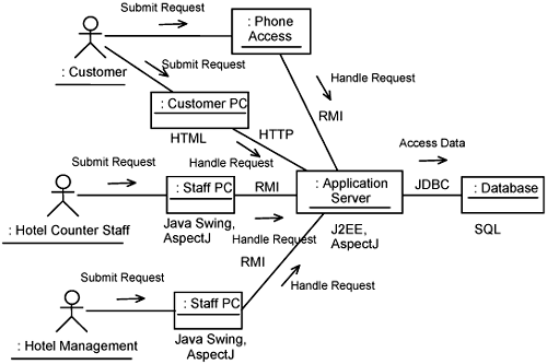
The platform specifics for a system are based on the deployment structure and process structure chosen by the architect. In this case, we assume that the architect has chosen a J2EE-based solution. Figure 11-3 depicts the deployment structure for the Hotel Management System. It is annotated with the architect’s choice of communication mechanisms, implementation languages, and technologies.
Figure 11-3 depicts actors so you can readily see how the deployment structure relates to the use-case model. The customer accesses the system through a phone or his own PC. The customer PC interacts with the application server over a wide area network over HTTP. The application server accesses that database to retrieve records, update records, and so on. Access to the application server is through Remote Method Invocation (RMI). Hotel counter staff and hotel management access the system through their PCs. Staff PCs uses Java Swing, which is a GUI framework for Java. For those nodes that use Java as a programming language, AspectJ is used as the composition technology.
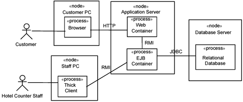
Zooming into each deployment structure, you find active elements (i.e., processes and threads) executing. This is depicted in Figure 11-4, which shows the customer PC running a browser, whereas the staff PC runs a thick client. The application server runs a Web container and an EJB container. The staff PC communicates using HTTP with the Web container, which in turn communicates with the EJB using RMI. The thick client communicates with the EJB container directly. The EJB container communicates with the relational database using Java Database Connectivity (JDBC).
Even with a chosen deployment and process structure, there are still many platform-specific implementation technologies to be chosen. You most definitely do not want to be tied down to a particular execution platform or even to a particular vendor. Platform-specific technologies evolve, and a new and better version becomes available regularly. It would be disastrous if you had to modify the design just to keep up with the changes in these technologies. Thus, you would like to keep platform specifics separate.
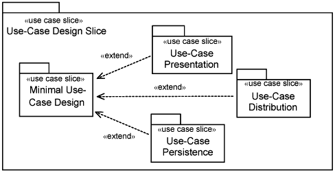
If you strip away the platform specifics from the design of a use case, what remains is a minimal use-case design. This minimal use-case design has the following characteristics:
It is executable and is implemented in a default programming language such as Java.
It is activated through a program interface. A separate program triggers the minimal use case. In this way, all concerns on user interface, presentation of information, and data input mechanisms is kept out of the minimal use-case design.
Concerns about distribution, interprocess communication, and platform-specific messaging are kept separate from it. So, the minimal use case design appears to run on a single node, a single process, and a single thread, when in fact it is running on the chosen platform described earlier.
Every piece of information it needs is assumed to be in memory. In this way, all persistency concerns are not present in the minimal design. Likewise, each action from the actor instance is an atomic action.
Everything else (user interface, distribution, etc.) is considered platform-specific and is designed separately and overlaid on top of this minimal use-case design.
Figure 11-5 shows a use-case design slice decomposed into the minimal use-case design slice plus several platform-specific slices for the use case. There is a platform-specific slice to modularize the user interface design for the use case, another platform-specific slice to modularize the distribution of the use case, and yet another to handle platform-specific persistency. There could be potentially other platform-specific slices, depending on what kinds of platform specifics you want to overlay on top of the minimal use-case design slice.
The benefits of separating the platform-specific parts from the minimal use-case design are many. First, the minimal use-case design is significantly simpler. Anyone who knows the designated programming language can develop it without knowing all the platform specifics. The minimal use case design is easy to design and develop, and you can produce an executable quickly. It is also much easier to test because it does not require any platform-specific test environment.
Establishing resilient architecture early in the project is critical. The goal is to make the system robust and reduce the impact of requirement changes and changes elsewhere in the system. It also make the system easier to understand. From an aspect orientation point of view, a resilient system makes your pointcuts easier to define because all the classes and responsibilities you need to extend are localized.
The way you establish the structure of models that describe the system is iterative. You start with some initial platform-independent structure. You then analyze the architecturally significant use cases one by one. As you do so, you add on and refine the existing structure and incorporate platform-specific elements onto the structure. After going through all the architecturally significant use cases, you will have established a fairly resilient architecture.
In the subsequent chapters, we explain how to handle different kinds of crosscutting concerns with different kinds of use cases. This will help you understand the general approach to aspect-oriented software development.

