A system needs to meet a set of nonfunctional requirements such as security, reliability, performance, and supportability. These are provided by a set of infrastructure use cases. Traditionally, the realization of application use cases tends to be tightly coupled with the infrastructure because the former makes direct calls to the infrastructure. As an implementation technique, you can use aspects and pointcuts to factor out the infrastructure. On top of that, you need a way to modularize infrastructure concerns. You achieve this with infrastructure use cases. It is common to find the same infrastructure use case being attached to different parts of the application. To improve reusability of infrastructure use cases, you model them as extensions to an application use-case pattern. You first define the pointcuts generically with reference to this application use-case pattern. Thereafter, you specialize and parameterize the pointcuts for the actual application use cases. This two-step approach keeps both the application and the infrastructure separate from one another.
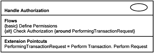
A resilient system attempts to separate the infrastructure from the application. This separation must begin with requirements and be preserved through analysis, design, and implementation. In Chapter 7, “Capturing Concerns with Use Cases,” we discussed the treatment of infrastructure use cases as extensions to application use cases. This makes the application independent of the infrastructure. At the same time, you want to minimize the dependency from the infrastructure to the application. So, you describe infrastructure use cases as extensions to some application use-case pattern. We have such a use-case pattern known as the 〈Perform Transaction〉 use case. As an example, in Figure 14-1, we show the Handle Authorization infrastructure use case as an extension of the 〈Perform Transaction〉 use case.
As can be seen in Figure 14-1, the application and the infrastructure are separated from a use-case-modeling perspective. Now we want to maintain that separation when we realize the system. We demonstrate briefly how this is achieved through the Handle Authorization as an example.
Infrastructure use cases may have basic flows, which means that actors can initiate them directly. For example, the Handle Authorization use case depicted in Figure 14-2 has basic flows for defining user permissions.
The infrastructure is an important part of a system, and much of the technical complexities in a system lie in the infrastructure. Therefore, you need to spend time analyzing its requirements and establish a resilient structure, as you did for application use cases. In the discussion to follow, we use analysis stereotypes—boundary, control, and entity—as the constructs to conduct analysis. We do not advocate jumping straight to the platform specifics when dealing with infrastructure (i.e., crossfunctional or nonfunctional) requirements. If you do so, you will be quickly swarmed by the platform specifics and lose sight of the requirements you have to meet. Instead, you ought to proceed from a platform-independent perspective. You will find the analysis stereotypes extremely useful to hide the implementation details. Furthermore, at this level of abstraction, it is easier for you to define a structure for the lower layers of the system. It is also easier for you to borrow from your past experience on the infrastructure (which could be on a different platform altogether).
Analyzing infrastructure use cases is similar to analyzing application use cases. The analysis of the Define Permissions use-case flow is simple, and we do not need to describe it further. The analysis of the Check Authorization extension flow, however, needs further discussion, which is the goal of this section. Unlike a normal extension use case in the application layer, which usually extends a single base use case, an infrastructure use case may extend or crosscut many application use cases. Thus, you analyze extension flows (e.g., Check Authorization in Figure 14-2) with reference to an application use-case pattern. As mentioned earlier, such a generic use case can be modeled through the reference 〈Perform Transaction〉 use case. The 〈Perform Transaction〉 use case serves as a template and a reference by which other application use cases are modeled and analyzed.
Let us identify the classes that participate in the realization of the Check Authorization extension flow. This will comprise the parameterized classes: 〈Boundary〉, 〈Control〉, and 〈Entity〉, which realize the 〈Perform Transaction〉 use-case pattern. These classes are shown on the left of Figure 14-3. We put these classes in brackets, 〈 〉, to indicate that they are parameters to the Handle Authorization use-case slice. We subsequently bind these parameters using pointcuts.
In addition, you need classes to provide the authorization capability. These classes are listed on the right-hand side of Figure 14-3. The Authorization Handler coordinates the interactions between classes that are involved in this use-case realization. The Access Control List class keeps track of which user is able to do what with the system. The Session class tracks the user actions from the time she logs in to the time she logouts.
You normally start the analysis of a use-case flow at the point when the use-case flow is triggered. For basic flows, the triggering event is typically the result of some actor initiation. For alternate flows, or for that matter, extension flows, the triggering point occurs at the point designated by the pointcut. Thus, the first step in analyzing an infrastructure use-case extension flow is to determine where the pointcut will be pointing to in the realization of the 〈Perform Transaction〉 use case.
The basic flow of the 〈Perform Transaction〉 use case is shown in Listing 14-1. It describes the pattern involving how an actor retrieves and displays some data on the form. Please note that Listing 14-1 describes only a general and simple case. There are, of course, many variations to this simple case, and you can describe them if necessary using alternate flows or extension flows in a separate infrastructure use case.
Example 14-1. 〈Perform Transaction〉 Use-Case: Basic Flow
The use case begins when an actor instance performs a transaction to access or manipulate the values of an entity instance. The system prompts the actor instance to identify the desired entity instance. The actor instance enters the values and submits his request. The system accesses the entity instance and displays its values. The use case terminates.
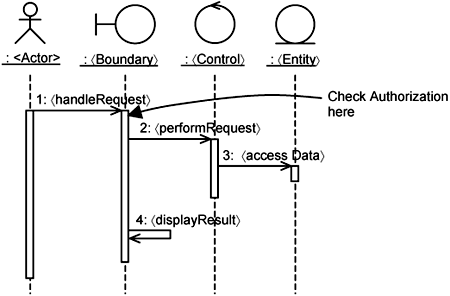
The realization of the 〈Perform Transaction〉 use case is shown in Figure 14-4. It contains actor instances and class instances, each parameterized with brackets. The interaction between the instances is described simply, as follows: the actor instance performs a request through a 〈Boundary〉 instance, which delegates the processing to a 〈Control〉 instance. This 〈Control〉 instance invokes some data-access operations on an 〈Entity〉 instance. The 〈Boundary〉 instance then displays the results.
You now identify the context for executing the authorization check. This is based on the Check Authorization extension flow in the Handle Authorization use case (Listing 14-2).
Example 14-2. Check Authorization Extension Flow
This extension flow occurs around the pointcut
PerformingTransactionRequest.
The system checks if the actor has sufficient authorization for the request to be performed. If the actor has sufficient authorization, the system proceeds with the request. Otherwise, an error is raised.
Extension Pointcut
PerformingTransactionRequest = 〈Perform Transaction〉.Perform
Request.
You now map the extension flow to analysis. This means you have an operation extension that is responsible to checkAuthorization. You also need to identify the structural and behavioral context whereby this operation extension executes—that is, you must map the extension pointcut in the extension flow to the pointcut in the operation extension.
You choose a class and responsibility (which will be refined into operations during design) where you can get information about the user or the session conveniently. Let’s assume that you have access to such information at the 〈Boundary〉 class. You execute the operation extension there—more specifically, within the 〈handleRequest〉 operation.
You now decide where within the 〈handleRequest〉 operation the checkAuthorization operation extension will execute and how it will execute (i.e., the behavioral context). This occurs when a call to the 〈performRequest〉 operation in the 〈Control〉 instance is made. Thus, you have a pointcut:
performingRequest = call (〈Control〉.〈performRequest〉 )
In addition, you want to gain control of the 〈performRequest〉 operation in the 〈Control〉 instance—control in the sense that the checkAuthorization operation extension will determine if 〈performRequest〉 can proceed. You achieve this using the around modifier, because if the checkAuthorization fails, the entire 〈performRequest〉 operation will be bypassed; that is, execution will go around the whole 〈performRequest〉 operation. If checkAuthorization passes, the whole 〈performRequest〉 operation will proceed.
You now have the complete operation extension declaration in analysis, which is formulated as follows:
〈handleRequest〉 { around (〈performingRequest〉) checkAuthorization}
Since the 〈Perform Transaction〉 use case is not an actual use case but a pattern or template, the pointcut 〈performingRequest〉 is also a parameter. You must bind the parameters to actual use-case realizations subsequently. We demonstrate that in Section 14.3.
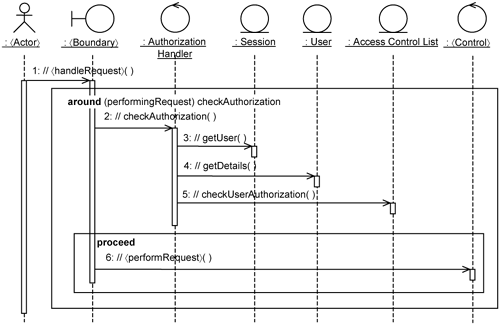
Now that we have identified where the checkAuthorization extension needs to be executed within the 〈Perform Transaction〉 use-case realization, we can describe the interaction between the participating class instances as shown in Figure 14-5. Figure 14-5 contains two frames. The first is labeled as follows:
around (〈performingRequest〉) checkAuthorizationIt represents the operation extension inserted into the 〈handleRequest〉 operation of the 〈Boundary〉 class. This operation extension gets the 〈Boundary〉 to check authorization through the AuthorizationHandler. The AuthorizationHandler instance gets the user from the Session instance. You can assume that the user details have been associated with the Session instance when the user logs in to the system. This is achieved through the realization of the Login basic flow of the Handle Authorization use case. Based on the user details (i.e., user Id, user role), it checks the user’s privileges through the Access Control List. If the user has the required authorization, the rest of the 〈handleRequest〉 proceeds. Otherwise, an error is raised.
Proceeding with the rest of the 〈handleRequest〉 in the 〈Boundary〉 is represented by the second frame. AOP provides a proceed keyword to achieve this.
The way you describe the interaction between the instances participating in an infrastructure use case is the same as that for a normal application use case. The usual practice applies. For example, an entity instance should not invoke a boundary instance subscribes to changes in the entity instance). In general, you should let a control instance do most of the coordinating work.
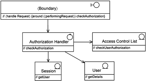
From the messages between the instances, you can identify the responsibilities of the participating classes. You can summarize the class responsibilities and the pointcut definitions in a class diagram, as shown in Figure 14-6.
Each box in Figure 14-6 represents a partial definition of classes relevant to the realization of the Check Authorization flow. You must explore the complete set of flows to find all responsibilities of each participating class. This takes place iteratively across the project life cycle. Note that the pointcut is not shown in the class diagram below. It is shown later when we define the aspect that contains the class extensions specific to the Handle Authorization use case.
Continuing with the Handle Authorization use case, you refine the model structure to keep the concerns about authorization separate from the application use cases it extends. This means refining the element structure and the use-case structure.
Consider if there are classes that are functionally related to each other. By functionally related, we mean that they are expected to evolve and change together. You put these classes in a service package. Since you are now dealing with the infrastructure, we call such packages infrastructure service packages.
Consider if there are reusable classes. If so, you can put them in a package in a lower layer. These packages support different infrastructure service packages, and we call them infrastructure support packages. Infrastructure services and infrastructure support form two layers in the infrastructure.
Frequently, infrastructure support packages are provided by the underlying platform in the form of some middleware. This means that you will seldom need to develop them. Instead, you will just make use of them through the infrastructure service packages. These packages are like the glue that binds the application to the underlying infrastructure.
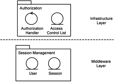
After making these considerations, you can package the infrastructure classes as shown in Figure 14-7.
The Authorization Handler and the Access Control List are for the sole purpose of handling authorization and are closely related. Hence, we put them in an Authorization infrastructure service package. The Session and User classes are used by other infrastructure services, such as auditing and profiling. Since they are reusable, we put them in an infrastructure support package.
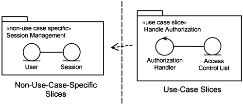
Now that you have determined where the classes that realize the Handle Authorization use case should reside in the element structure, you must determine how they are added. The Session Management classes are fundamental to several infrastructure services and are therefore added through a non-use-case-specific slice named Session Management, as depicted in Figure 14-8. The Authorization Handler and the Access Control List are added through the Handle Authorization use-case slice.
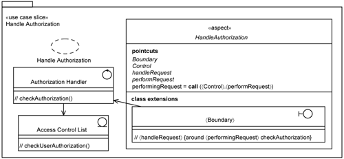
Let us take a closer look at the Handle Authorization use-case slice (see Figure 14-9). It comprises the classes and features that are specific to the realization of the Handle Authorization use case. It contains a collaboration (also named Handle Authorization) that describes the interaction between the participating classes. It contains the Authorization Handler and the Access Control List.
The Handle Authorization use-case slice also contains an extension of the 〈Boundary〉 class that it extends. This class extension is housed within an abstract aspect, HandleAuthorization (depicted in italics). It is abstract because the pointcuts, though identified, are not defined; that is, the pointcuts are named but no expression is spelled out.
The Handle Authorization use case has been analyzed with reference to a 〈Perform Transaction〉 use-case pattern. Thus, you find that a number of parameters are currently unbound. These parameters are Boundary, Control, and HandleRequest. Recall in Chapter 9, “Keeping Extensions Separate with Pointcuts,” we described two ways to express parameters:
Through the pointcut mechanism in AOP.
Through template parameters.
Both are possible, but in this case, we want to take advantage of the first method by using aspect-generalization capability. Thus, the parameters Boundary, Control, and HandleRequest are expressed as abstract (depicted through italics) in Figure 14-9. Accordingly, the HandleAuthorization aspect is also abstract. Thus, you have a prebuilt use-case slice waiting to be specialized and attached to an actual use-case slice. The next section demonstrates how you can specialize the HandleAuthorization aspect.
In the previous section, we demonstrated how you can analyze infrastructure use cases using Handle Authorization as an example. The result is a Handle Authorization use-case slice that contains an abstract HandleAuthorization aspect. You now have a generic authorization component that is being attached to a generic or fictitious 〈Perform Transaction〉 use case. The next step is to attach an authorization component into some concrete application use cases.
As an example, we demonstrate how you can attach the infrastructure use-case slice (e.g., the Handle Authorization use-case slice) to an actual application use case (e.g., Reserve Room use-case slice). We also recognize that there are alternatives to AOP during implementation. We demonstrate how an infrastructure use-case slice maps to object-oriented frameworks (e.g., J2EE). Specifically, we consider J2EE Servlet Filter as an alternative means to keep infrastructure separate.
We complete this discussion by demonstrating how you can componentize the infrastructure and integrate these infrastructure components with application components through aspects or object frameworks.
As an example, let’s assume that you want to apply the Handle Authorization use case to the customer package. Thus, you can specialize the abstract HandleAuthorization aspect in Figure 14-9 into a concrete CustomerApplicationAuthorization aspect.
Let’s look at how you can define the pointcut expressions for the CustomerApplicationAuthorization aspect. Suppose you want to subject all the boundary classes to authorization checks. You can define the Boundary pointcut as follows:
Boundary = customer.app.«boundary» *
We have just introduced in the pointcut value expression a matching criteria based on the stereotype: «boundary». Thus, customer.app.«boundary»* refers to all classes within the customer.app package that are of the stereotype «boundary» of any name. You can see that the matching criteria need not be restricted to element names. In general, you can use element names, stereotypes, and tag values. In fact, you can use any modeling mechanism that distinguishes one element from another.
Since most programming languages currently do not have constructs for stereotypes and tag values, the naming convention during implementation must have some prefix or suffix to indicate the kind of stereotype and tag values the element is mapped from.
In AspectJ, pointcut expressions can use the + character to refer to all the children of a particular class. You can define the Boundary pointcut as follows:
Boundary = Form+
This means that you are applying the aspect on all children of the Form class in the customer package. You can likewise define the pointcut to bind Control to all Handler classes as follows:
Control = Handler+
In this particular case, we do not restrict which package Control classes belong to. This is because Control classes might not be limited to the customer.app package. They may reside in the lower domain-specific layer as well as in the application-specific layer.
You can now summarize the pointcut expressions for the CustomerApplicationAuthorization aspect, as shown in Figure 14-10.
In 14-10, the responsibilities 〈handleRequest〉 and 〈performRequest〉 are bound to wildcards. This means that the authorization will be checked for every request that the actor initiates. In reality, you may want to impose restrictions on the kind of request you want to check. These restrictions will be project-specific.
AOP is but one technique for you to keep infrastructure use cases separate. Object-oriented frameworks such as J2EE provide an alternative solution. In J2EE, a servlet is a Java program that executes on a HTTP Web server. It handles requests from an HTTP client (e.g., a Web browser) and generates responses typically as HTML output. The J2EE servlet specification provides a filtering mechanism that allows you to implement crosscutting concerns such as authorization at predetermined points. A filter dynamically intercepts requests to a servlet and responses from a servlet. The filter can modify requests or responses or both. Typically, filters themselves do not create responses, but instead provide universal functions that can be “attached” to any type of servlet.
Simplistically, the operation of the filtering mechanism for J2EE servlets works as shown in Figure 14-11.
Instead of getting the servlet to process a request from an actor directly, the filtering mechanism passes the request through a series of filters before it reaches the servlet. The response from the servlet then passes through the same series of filters in the reverse direction. Each filter can act based on the request and even modify the request and response parameters. It can also prevent the request from flowing downstream and return the result immediately. As you can see, the filters are lined up like a chain, so in J2EE, they are collectively called a filter chain.
This servlet-filter mechanism is an example of the Composition Filters approach to separate concerns [Bergmans et al. 2001]. The servlet-filter mechanism can be used to implement the authorization use-case slice. In this case, you can map the abstract HandleAuthorization aspect we discussed earlier (see Figure 14-10) to an abstract filter. This abstract filter deals with user requests. In addition, you need a corresponding concrete filter to deal with authorization specific to the customer application as a counterpart to the CustomerApplicationAuthorization aspect (see Figure 14-10).
Figure 14-12 shows how this is achieved. The left-hand side shows two interfaces provided by the J2EE servlet library. Simplistically, the Filter interface defines a doFilter() that accepts a request and produces a request.
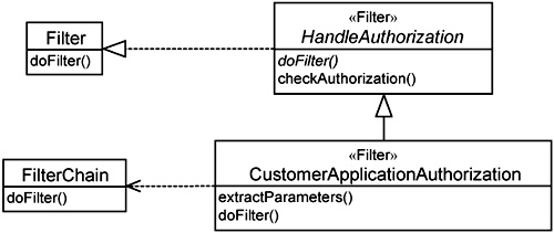
Figure 14-12. Classes participating in HandleAuthorization implemented using servlet-filter mechanism.
The FilterChain interface defines an operation with the same name, doFilter(). This operation gets the next filter in the filter chain to perform doFilter().
The right-hand side of Figure 14-12 shows the classes you will implement. They are both counterparts of the HandleAuthorization and CustomerApplicationAuthorization aspects respectively. The HandleAuthorization filter has two operations: doFilter() is abstract, and the checkAuthorization() operation performs the actual authorization checks. It accepts the names of the Boundary and Control classes and the use-case operation being initiated by the actor as input. Based on these three inputs, it determines if the actor has sufficient authorization.
The detailed sequence of events for the doFilter() operation in the CustomerApplicationAuthorization class is depicted in Figure 14-13. It first extracts parameters from the filter request. The request contains strings indicating which boundary class, which control class, and which action the actor is initiating. The CustomerApplicationAuthorization instance calls the checkAuthorization() operation defined in its parent. If authorization passes, it calls the next filter in the filter chain.
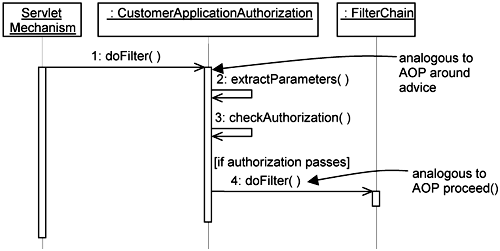
Figure 14-13. Interaction diagram for HandleAuthorization implemented using servlet-filter mechanism.
Thus, the HandleAuthorization filter provides generic authorization, and the CustomerApplicationAuthorization filter attaches it to actual application classes. This mirrors the approach we presented earlier using AOP. Specifically, the doFilter() operation is analogous to an around advice in AOP, and the doFilter() operation on the FilterChain is analogous to the proceed keyword in AOP.
What you see here are two ways for you to design and implement infrastructure use case. Let’s compare the solutions you can achieve AOP with servlet filters. Both are able to keep authorization concerns separate in an unintrusive manner. The servlet filter defines a fixed execution point (known as a join point in AOP) whereby additional behaviors can be executed, specifically by implementing the Filter interface and the doFilter() operation.
AOP is more general, and with powerful primitives to express join points, it can be used to extend different parts of the system with additional behaviors. Thus, AOP is more flexible. But flexibility must be supplemented with guidelines. You do not want the owner of different use cases to add authorization behaviors at different places without architectural control. The 〈Perform Transaction〉 use-case pattern gives you a reference to anchor the pointcuts for your infrastructure use cases.
Whichever way you choose, whether AOP or filters, you still go through the same steps of use-case specification, use-case analysis, and refinement of the element structure, which we discussed earlier in this chapter. When it comes to design and implementation, you choose the most appropriate technique. Consider if a fixed-point extension offered by servlet filters is sufficient. If not, choose AOP techniques to find a better extension point.
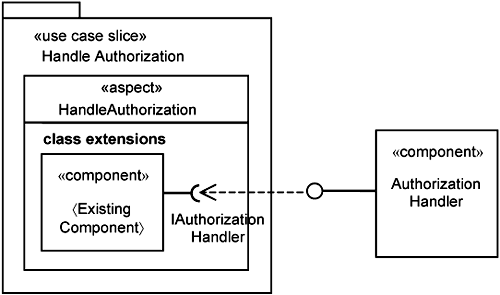
Handling authorization is a common capability needed by most systems, so it makes sense to develop a component for it. Your system should also provide the means for you to plug in this authorization component. This is achieved through the Handle Authorization use-case slice, which is depicted in Figure 14-14.
The Handle Authorization use-case slice has a HandleAuthorization aspect, which can extend existing components with a required interface, IAuthorizationHandler, whereby you can plug in a AuthorizationHandler component. We have shown two approaches to extending components: through AOP (specifically use-case slices) and through filters.
With the AOP approach, you can extend each component individually. With the filter approach, you extend many component at once, since all calls to these components go through the filter mechanism first. This filter mechanism can of course be introduced into the system through a use-case slice.
In general, there will be a number of infrastructure use cases for your system. Not only do you want to keep the infrastructure use cases separate from the application use cases, you want to keep infrastructure use cases separate from each other. In fact, you should keep concerns and use cases of all kinds separate from each other. So, if there are any changes in the use cases, such changes will have minimum impact on other use cases. If you can achieve that, you have a very resilient system.
The fact that infrastructure use cases are analyzed with reference to a 〈Perform Transaction〉 use-case pattern is useful. Through the 〈Perform Transaction〉 use case, you can easily consider how to overlay multiple infrastructure use cases simultaneously. They are, after all, extensions of the same 〈Perform Transaction〉 use case.
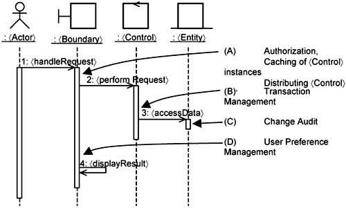
To make the discussion concrete, we consider the 〈Perform Transaction〉 use case being extended by Authorization, Caching, Distribution and Transaction Management, Change Audit, and User Preference Management. Figure 14-15 shows where they may be potentially executed within the 〈Perform Transaction〉 use-case realization.
In Figure 14-15, arrows indicate the execution points where some exemplary infrastructure use cases are added:
At execution point A, which occurs at the beginning of the
〈handleRequest〉responsibility, you can execute an authorization extension, which we discussed earlier. You can also execute extensions that provide the caching and distribution of〈Control〉instances here.At execution point B, which occurs before any
〈accessData〉, you can execute a transaction management extension. This helps provide atomic updates to datastore, handle concurrency issues, and so on.At execution point C, which occurs with the
〈accessData〉operation, you can execute the logging extension to save changes to a datastore.At execution point D, which occurs just before the
〈Boundary〉instance〈displayResult〉, you can execute an extension to track user inputs and to change the display according to his or her preferences.
We now explore the possible dependencies between the infrastructure use cases and discuss how to deal with them.
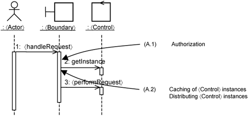
Sometimes, infrastructure use cases (specifically, their extension flows in use cases, which are translated to operation extensions) are attached to the same execution point. Execution point A is such an example. In such cases, you must determine whether they are indeed attached to the same execution point. Figure 14-15 is, after all, a relative high-level depiction of the interactions between instances. You need to zoom in further to uncover more detailed interactions. Thus, Figure 14-15 is expanded into Figure 14-16.
In Figure 14-16, the 〈handleRequest〉 operation has two steps:
A call to the
〈Control〉classifier togetInstance(); the purpose ofgetInstance()is to get an instance of the〈Control〉class.A call to the
〈Control〉instance to〈performRequest〉.
This refinement shows that the authorization extension is executed at a different execution point than in the other two infrastructure use cases. The authorization extension occurs at the beginning of the 〈handleRequest〉 operation, whereas caching and distribution extensions occur around the getInstance() operation.
The objective of caching is to reduce the need to create 〈Control〉 references every time a 〈Control〉 instance is needed. The objective of distribution is to hide the fact that the 〈Control〉 instance is in reality executing on a different processing node. Though they have distinct purposes, they execute around the getInstance() operation.
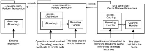
In conventional programming, you can indicate the order in which infrastructure use cases are attached by simply ordering your programming statements in the existing code. However, with aspect orientation, you are overlaying operation extensions on top of existing operations, so you must define how overlaying is conducted. For example, you might want the distribution to be overlaid first and caching of remote instances on top of that. In this case, you have distribution as an extension of the 〈Perform Transaction〉 use case and caching of remote references as an extension of distribution. In use-case modeling, this is modeled as shown in Figure 14-17.
Please note that extensions of extensions do not necessarily lead to having aspects of aspects or operation extensions of operation extensions (i.e., advices of advices). This is because operation extensions are meant to be small. They should delegate the actual work to other classes, and you subsequently overlay on top of these classes. This is illustrated in Figure 14-18.
On the left, you see the 〈Boundary〉 class that participates in the realization of the 〈Perform Transaction〉 use case. To the right of the 〈Boundary〉 class is a Handle Distribution slice. It has an aspect named Distribution, which contains a 〈Boundary〉 class extension. This contains an operation extension that replaces local calls with remote calls in the original 〈Boundary〉 class on the left. Now, the operation extension in the 〈Boundary〉 class extension does not create the remote instances. Instead, it delegates the responsibility to a class named RemotingHandler.
To the right of RemotingHandler, you see the Cache Remote References use-case slice. In the same manner as above, it has a Caching aspect that adds an operation extension into the RemotingHandler to cache remote instances. This is achieved using the CachingHandler class. Thus, you see that in this case, you can avoid overlaying aspects on top of aspects. The implementation is much easier to understand.
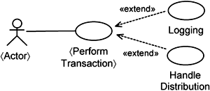
Sometimes, you do have extensions at the same exact point. For our example, we have a Logging extension use case and a Handle Distribution use case on the 〈Perform Transaction〉 use case, as depicted in Figure 14-19.
Let’s say both extensions occur at the same point. They need to be independent and there should be no ordering between them, otherwise, the design becomes complicated. The situation becomes worse when you want to parameterize pointcuts to cover a large number of classes and operations. Thus, you should have either extensions of extensions realized, as shown in Figure 14-18, or extensions where order is not important, as shown in Figure 14-19.
In addition to considering multiple infrastructure use cases on top of the 〈Perform Transaction〉 use case, you also need to consider the variations that may occur in the application layer. The interaction in Figure 14-15 considers only the basic flow of the 〈Perform Transaction〉 use case. The variations can be effectively modeled as alternate flows of this basic flow.
You must consider what are the acceptable behaviors of the infrastructure use cases to such variations and handle them accordingly. This may result in:
Identification of other infrastructure use cases.
Identification of additional alternate flows in existing infrastructure use cases.
Both will lead to identification of more operation extensions and pointcuts for the infrastructure use cases. To resolve potential conflicts, you need to consider multiple use-case slices and aspects at once, as we demonstrated in this chapter. The benefit you get with use-case modeling is that you can quickly get an overview of the possible conflicts and refactor them with a use-case diagram such as in Figure 14-17 and Figure 14-19.
In this chapter, we showed you how to keep the infrastructure separate from the application and how to keep each infrastructure services separate from each other. This prevents changes to one infrastructure service from propagating to another. Thus, resilience is achieved. You keep extensions separate by treating infrastructure use cases as extensions to application use cases. Use-case modeling gives you an added advantage—you have a high-level view of how you structure them effectively.
Central to our approach is the use of the 〈Perform Transaction〉 use-case pattern as a reference for analyzing infrastructure use cases. The result is a generic infrastructure use-case slice that you can specialize to attach to actual application use-case slices. The 〈Perform Transaction〉 use case also acts as a base on top of which you can consider the possible dependencies between infrastructure use cases. You can then either keep infrastructure use cases separate or merge them if appropriate.
AOP represents one way for you to keep infrastructure use cases separate. It is not the only technique. The filter approach is an example of another technique. In fact, AOSD is about systematically applying a host of techniques to solve the problem of separation of concerns and achieving better modularity. You apply AOP, you apply filters, you apply design patterns. Even object-oriented frameworks are techniques available to you.


