Use cases provide the means to model and separate crosscutting concerns effectively, but you must preserve the separation of concerns through design and implementation. This means that you have to collate the specifics of a use case during design in some modularity unit, which we call a use-case slice. Each use-case slice collates parts of classes, operations, and so forth, that are specific to a use case in a model. The task of composing these parts is left to some composition mechanism (provided by aspect technology). The developer no longer needs to perform this step, and from this perspective, he or she no longer faces tangling from other concerns. This makes his or her code much cleaner and easier to understand. We extend this concept even further—a use-case module that collates the specifics of a use case from all models and artifacts in a project into a single unit. This is advantageous because it is now much easier to manage system configurations, and parallel development is now simplified tremendously.
When you realize a use case, you identify the required classes and features (attributes, operations, and relationships) of these classes. Some of these classes and their features are specific to this use-case realization, while others are needed by other use-case realizations. In this section, we introduce the concept of a use-case slice. Each use-case slice keeps the specifics of a use-case realization in one model (e.g., the design model). Those generic and reusable parts are kept in non-use-case-specific slices. All these slices are then superimposed to form the entire design model.
Recall our home construction analogy in the preface. This analogy helps us understand what a use-case slice is. When an electrician wants to wire the house, he first describes his intent by drawing lines on a floor plan. The floor plan gives the locations and dimensions of walls, doorways, and so on. From this information, the electrician knows how much work needs to be done. If another specialist wishes to lay phone lines, she takes a floor plan and draws out where the phone lines will be laid. You can get each specialist to draw what he or she intends to do on an overlay (a transparency used on overhead projectors). You can easily sum up the work done by stacking up these overlays and projecting them on the screen. Of course, each overlay must be based on the same floor plan and the same scale.
So, use-case slices are analogous to overlays, and composition is simply stacking them on top of each other. The floor plan is analogous to what we call the element structure. A model (e.g., a design model) comprises a hierarchy of elements. You find packages containing classes, classes containing operations, and so on. This hierarchical organization is the element structure.
An element’s qualified name within the element structure is the path from the top-most element to the element itself. This means that you can uniquely identify a particular element in the model by looking at its fully qualified name. This qualified name is extremely important during composition because it is used by the composition mechanism to determine if elements on two separate use-case slices refer to the same element in the element structure.
Use-case slices are separate from the element structure. They are overlaid on top of the element structure and define its contents; that is, they define behaviors that extend the element structure. Use-case slices have dependencies among themselves that describe which use-case slice (or overlay) should be placed first, which should be next, and so on. This leads to another structure, which we call the use-case structure. It is a hierarchy of use-case slices. Thus, a model comprises two structures:
The element structure, which identifies elements.
The use-case structure, which defines the content within these elements.
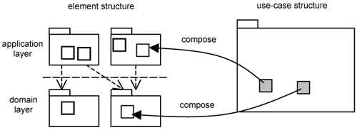
This composition is illustrated in Figure 4-1. On the left, you see the element structure organized hierarchically in terms of layers, packages, and classes. On the right, you see the use-case structure. For simplicity, we show only one use-case slice, which is stereotyped as «use-case slice». The use-case slice contains element extensions that will be composed (such as through an aspect weaver) into the model with reference to the element structure.
As can be seen in the figure, the element structure is just a means to identify where elements in the model reside. You treat the elements (i.e., classes) like empty boxes. Their contents (i.e., behavior) will be filled by use-case slices during composition.
Up until now, the use-case structure could not be kept separate from the element structure. A developer would have to collate all responsibilities on each class from different use cases and develop the class. This leads to tangling and scattering. But now, by keeping the use-case structure separate from the element structure, the separation of use cases can be preserved.
We earlier highlighted two specific cases that we have been unable to keep separate—peers and extensions. We demonstrate how this is solved through use-case slices.
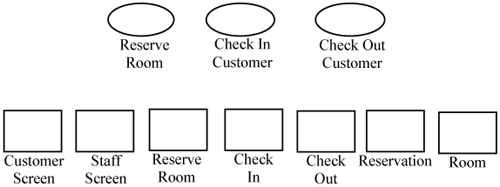
Let us begin with the realizations of peer use cases. Peer use cases are those that have no relationships between them. They are distinct and separate use cases, but their realizations overlap and they impose responsibilities on the same classes. The three use cases Reserve Room, Check In Customer, and Check Out Customer depicted in Figure 4-2 are peers. Their realizations impose a set of responsibilities on the classes listed in Figure 4-2.
After identifying classes, you must identify the features (i.e., attributes, operations, and relationships) of each class needed to realize the use cases. You do not sum up the features for each class from the various use-case realizations, since doing so would end the separation of use cases and result in tangling within classes.
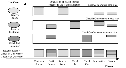
Instead, you collate the features of each class that are specific to a use-case slice. Thus, each use-case slice may not have complete classes. Instead, they have parts of classes, which we call class extensions. In essence, a class extension contains only the features of a class needed to realize a specific use case. The result is depicted in Figure 4-2. It shows three use-case slices containing extensions of classes identified in Figure 4-2.
In Figure 4-3, the horizontal axis shows the element structure that identifies the classes in the system. The vertical axis shows the use-case structure. It identifies the use cases being realized, each with a different shade. Each horizontal row depicts a use-case slice containing the extensions of classes needed to realize the use case for that row. Thus, we have the ReserveRoom use-case slice, the CheckInCustomer use-case slice, and the CheckOutCustomer use-case slice.
Each use-case slice contains partial class definitions (i.e., class extensions) specific to the use-case realization. If you want complete class definitions, all you need to do is merge all the use-case slices. In essence, the merging operation takes elements of the same name and merges them together. For example, the ReserveRoom use-case slice has a class extension named Room, and so do the CheckInCustomer and CheckOutCustomer use-case slices. Since the class extensions have the same name, they will be merged. The result is depicted in the bottom row of Figure 4-3. The resulting Room class is a composition of all the class extensions from the respective aspects as depicted by the different shades.
In UML today, the merge operation is modeled using the stereotyped «merge» dependency between packages. This merge operation can be implemented in AOP using intertype declarations. You can now keep the realizations and implementation of peer use cases separate from one another.
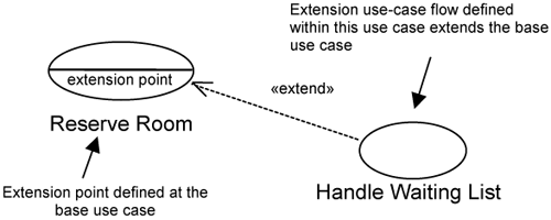
We now show how the realizations of extension use cases are kept separate. Let’s quickly recap extension use cases using our waiting list example in Chapter 2. Recall that we wanted to add a waiting list functionality (the extension) on top of the existing reserve Room functionality (the base). This is modeled through the extend relationship between two use cases, as depicted in Figure 4-4. The Handle Waiting List extension use case extends the Reserve Room base use case. The extension use case has a sequence of actions that must be inserted into the base use case at the extension point defined within the base use case. This sequence of actions is known as an extension use-case flow. It puts a customer on the waiting list. It is a separate concern from Reserve Room, but it is needed to provide the Handle Waiting List functionality and is, therefore, specified within the Handle Waiting List use case.
In UML today, extension points are just a means to give a label or a name to a point in the execution sequence of a use case. The extension use case references the extension point to indicate when the extension use-case flow will be inserted. AOP uses the concept of pointcuts to identify execution points during implementation.
The corresponding concept of extension points in AOP is known as join points. A join point is a point in the execution flow of a program with well-defined semantics (the execution of an operation, a call to an operation, the throwing of an exception, etc.). Pointcuts in AOP are a larger concept than extension points, as they are currently defined in UML today. In addition, pointcuts in AOP have the capacity to refer to multiple extension points (i.e., join points) that may be defined in multiple classes at once. This is advantageous especially for infrastructure mechanisms (authorization, logging, etc.) that cut across many classes. We show how pointcuts are modeled in use-case slices in Part III of this book.
An extension use-case flow is realized by an advice in AOP. An advice is the behavior to be executed at extension points designated by pointcuts. The equivalent of an AOP advice in use-case slices is what we term an operation extension. An operation extension is a modular extension to an existing operation to perform a behavior different from the operation’s main responsibility.
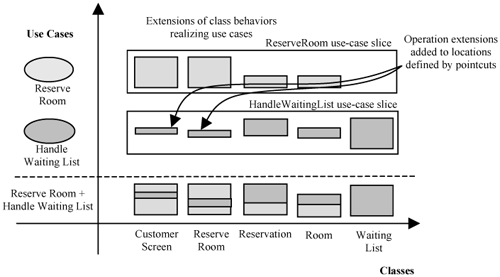
We can describe how we keep the realization of extension use cases separate as we did with peer use cases earlier. Figure 4-5 shows the composition of the realization of the Reserve Room and Handle Waiting List use cases. The horizontal and vertical axes represent the element structure and the use-case structure, respectively.
Each horizontal row in Figure 4-5 shows a use case and the class extensions (shown shaded) needed by its corresponding realization. Compared to the earlier example in Figure 4-3, we have an additional WaitingList class in the element structure. This class is required by the HandleWaitingList use-case realization but not by the ReserveRoom use-case realization. Hence, it does not appear in the ReserveRoom use-case slice.
In addition, the HandleWaitingList use-case slice has two operation extensions. These operation extensions (indicated by the arrows in Figure 4-5) are defined within the CustomerScreen and ReserveRoom class extensions, respectively. If you want the complete class definitions (with the complete operation behaviors), you need to merge the two use-case slices. The result is depicted in the bottom row of Figure 4-5. The merging works at a finer level of resolution compared to that discussed earlier regarding peer use-case realizations. This is because with peer use-case realizations, you merge complete operations by their names. With extension use-case realizations, however, you need to specify what the existing operation is doing when the operation extension must be inserted. This fine-grain merging or weaving is supported through pointcuts. Thus, with the advice and pointcut mechanism, you can keep the realization of extension use cases separate from the base.
We kept the above discussion simple by indicating that you compose peer use-case slices with intertype declarations and extension use-case slices with advices. In general, composition of both peer and extension use-case slices require both intertype declarations and advices.
Now that you can modularize extensions of classes needed by a use case in design using use-case slices, you can take a step further. You can modularize all elements and artifacts specific to a use case into a single module—we call this a use-case module. When we say all, we mean over all life-cycle models. Thus, a use-case module contains the use-case specification for the use case, the analysis of the use case, the design and implementation of the use case, the test associated with the use case, and all configuration and parameters needed by the use case. Just as you can compose extensions of classes and operations from multiple use cases to form the desired executable, you can likewise compose the extensions of other kinds of model elements and artifacts (analysis elements, design elements, implementation elements, etc.).
The ability to work with use-case modules independently greatly and positively impacts the way you conduct software development. Work on each use-case module can proceed separately and in parallel as separate projects. Of course, there is some architecture work to coordinate the names of elements, pointcuts, and so on.
Stakeholders and project managers benefit because the project team can attend to business concerns of the system early in the project. The project manager can postpone the selection of platform specifics (such as security, persistency, and distribution) and deal with them in a later iteration. In short, we now have more options to organize which part of the system we want to develop first. You can almost choose to deal with any concern in any iteration. We say almost because there will be some dependency between concerns, but being able to effectively separate concerns better than before allows greater freedom to choose which concerns to deal with first.
In addition, since most interesting concerns are modeled as use cases, the use-case model helps you identify relationships between concerns and decide how to plan iterations. You normally start with a set of core use cases that do not depend on anything else and gradually grow the system to incorporate use cases on top of this core.
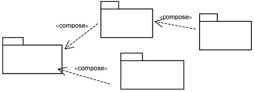
If you apply use-case modularity to the Hotel Management System, you might, for instance, start to build the use-case module for the Reserve Room use case (see Figure 4-6). In the next iteration, you can develop the use-case modules for Check In and Authorization separately and compose them onto the Reserve Room use-case module. The composition action is indicated by the «compose» relationship in Figure 4-6, which essentially means that you overlay a module onto another module. At a later stage, you might choose to develop and compose the use-case module for the Check Out use case. Or you might want to choose a different use case. If a use-case module needs to be modified, you simply replace it with a new one. The choice is really flexible, and all this is possible thanks to new modularity that is enabled by aspect orientation.
It is evident that keeping use cases separate all the way down gives tremendous benefit to the project team. Since everything about a use case is contained within a use-case module, systems developed this way are much easier to understand, maintain, and extend. But this does not mean that use-case modules can be developed totally independent of each other. There must be some architecture work involved. The architecture is not just about separation. It is also about composition. You need to analyze and evaluate runtime characteristics of the composed system as well. After all, the response time is the sum of all responses from all the use-case slices through which the execution path flows.

