
Chapter 2 Updating the Server
Rare is the system that remains static over its lifetime. Invariably, a server will be assigned to different tasks, moved from location to location, or either upgraded or replaced as more resources are required to perform its current duties. This chapter walks you through the various techniques required to maintain your systems throughout their life cycle.
The main focus of this chapter is to introduce techniques required to perform the following tasks:
![]() Navigate the two interfaces available for the YaST configuration tool
Navigate the two interfaces available for the YaST configuration tool
![]() Add and remove software components to your base server installation
Add and remove software components to your base server installation
![]() Manage critical disk space resources through the addition of additional hardware
Manage critical disk space resources through the addition of additional hardware
![]() Maintain the network interface
Maintain the network interface
Before we explore the intricacies of YaST, a brief explanation of the way SUSE maintains configuration settings is in order.
Maintaining Your System Configuration
SUSE LINUX Enterprise Server (SLES) maintains information about your system’s configuration in the directory /etc/sysconfig. The files and directories present in this location dictate the behavior of the various hardware and software components that make up your server.
When the time comes to reconfigure your server, the files in /etc/sysconfig have to be updated to reflect the change in resources. A proper understanding of the mechanisms involved in making such modification is necessary to allow you to quickly diagnose any difficulties that arise.
SuSEconfig
It is possible to maintain your system manually by editing files residing under /etc/sysconfig and then alerting the system’s services of the changes by running SuSEconfig. However, this approach is not recommended unless you have in-depth knowledge of the service you are maintaining and the syntax of its configuration files.
The same configuration files are often required for a number of services. Conversely, one service may depend on multiple configuration files in numerous distinct directories. Making manual changes to one service may have negative effects on others. If you choose to edit the configuration files, make sure to store backup copies first in case of an emergency.
The changes to the static setup files will not affect the functioning of the system until after their services have been restarted. The SUSEconfig utility is invoked to implement the changes.
WARNING
Manual editing of some files is required to gain access to certain advanced configuration features because they are not accessible using the GUI tools. For this reason, you may decide that you would like to maintain some configuration files manually.
It is important that you allow yourself a method for rolling back changes. Making a pre-edit snapshot, or backup copy, of the file you want to change is crucial. In the event of unexpected behavior, the offending configuration file can be quickly replaced without having to rely on the previous days’ backups. Depending on the significance of the change, the previous backup media might not be accessible!
Being paranoid is an integral part of system management. Having a quick restore point will save hours of frustration and downtime. Trading a little bit of disk space for peace of mind is a good investment at any time.
SUSEconfig is located in /sbin. This high-level utility invokes the necessary secondary scripts to implement configuration parameters defined in /etc/sysconfig. These scripts, located in the /sbin/conf directory, are named Suseconfig.subsystem-name. Each SuSEconfig script manages one of the subsystems currently installed on the server.
A drawback with SuSEconfig is that it is not the master of all the configuration files found in /etc/sysconfig. SuSEconfig does not handle a number of configuration files, notably the ones containing your machine’s IP address and volume information.
Limitations in the scope of the SuSEconfig utility, coupled with the intricate nature of modifying multiple files in multiple directories for a single change, make the manual reconfiguration of servers a daunting task. Though servers have been maintained this way for quite some time, a more consistent and efficient automated tool offered with SLES is YaST.
YaST (Yet another Setup Tool)
YaST, as its name implies, is a setup tool for configuring SUSE systems. This utility has been built to present a more intuitive GUI-based environment for maintaining system configuration files. YaST also organizes information drawn from multiple files in different directories into a simple, consistent presentation. This allows you to concentrate on the changes you are trying to make and removes the underlying complexities. Whenever possible, YaST leverages the SuSEconfig utility to manage subsystems.
The YaST configuration tool is accessible through two separate GUI interfaces. The Qt interface is present under the X Windows System, whereas the other uses ncurses and allows a GUI interface in a terminal environment. Both implementations allow you access to the full functionality of the application.
YAST INTERFACES
Both YaST interfaces can be invoked from a terminal session. In an X Windows System terminal session, you invoke the Qt version of YaST by typing yast2 at the command line. Navigation within yast2 is done with the mouse. In non-X terminal sessions, you invoke YaST by simply typing yast. The ncurses version of YaST is navigated using the arrow keys as well as Alt-letter combinations, where the letter required is highlighted within the keyword for each menu option.
You might wonder why both interfaces were created. The simple answer is that for a number of server environments, the X Windows System interface is simply not required. Keep in mind that it is imperative to run only the applications required to support a server’s tasking. Additional applications can potentially contain vulnerabilities that could compromise the environment.
Also, running these additional applications requires system resources. If the X Windows System interface is not used, the resources it and its associated routines consume would be better dedicated to the server’s applications.
On most servers, it is considered prudent not to install the X Windows System or run the server at runlevel 3. On such systems, the ncurses version of YaST allows you to quickly reconfigure the machine with minimal impact on system resources.
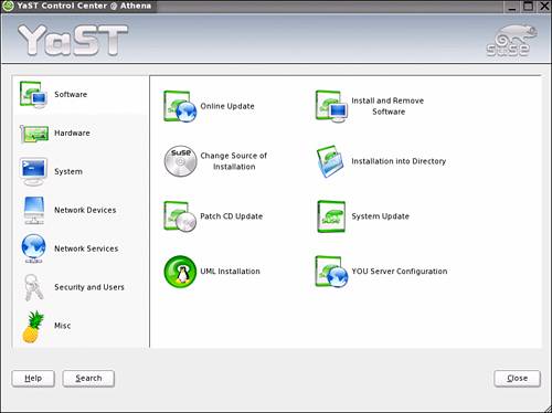
You can see the initial YaST menu for both interfaces in Figures 2.1 and 2.2. The main menu for the YaST tool subdivides maintenance into the following main categories:
![]() Software—This section allows you to control what modules are installed on your system, the location of the installation media, as well as how you keep the applications and services up to date. From this selection, you can configure User Mode Linux (UML) as well as your YaST Online Update Server.
Software—This section allows you to control what modules are installed on your system, the location of the installation media, as well as how you keep the applications and services up to date. From this selection, you can configure User Mode Linux (UML) as well as your YaST Online Update Server.
![]() Hardware—This section allows you to maintain the different hardware components of your system. Menu options found here cover your server’s controller cards for video, sound, and disk. You also can use this section to define peripheral devices such as printers and joysticks.
Hardware—This section allows you to maintain the different hardware components of your system. Menu options found here cover your server’s controller cards for video, sound, and disk. You also can use this section to define peripheral devices such as printers and joysticks.
![]() System—This section of YaST covers your system configuration. It allows you to fine-tune how your system will behave through startup, disk volume, and power management.
System—This section of YaST covers your system configuration. It allows you to fine-tune how your system will behave through startup, disk volume, and power management.
![]() Network Devices—This section defines how your server interacts with the outside world. Included in this submenu are server-network interfaces as well as service/appliance connections such as FAX and answering machines.
Network Devices—This section defines how your server interacts with the outside world. Included in this submenu are server-network interfaces as well as service/appliance connections such as FAX and answering machines.
![]() Network Services—In this section, you maintain the applications that define your server’s tasking. You should find configuration options that allow you to customize the services your machine offers. Included are the modules you installed in the Software menu option earlier in this list.
Network Services—In this section, you maintain the applications that define your server’s tasking. You should find configuration options that allow you to customize the services your machine offers. Included are the modules you installed in the Software menu option earlier in this list.
![]() Security and Users—This section allows you to define your password policies, users, groups, your server’s internal firewall settings, and the way your server will manage its certificates.
Security and Users—This section allows you to define your password policies, users, groups, your server’s internal firewall settings, and the way your server will manage its certificates.
![]() Misc—This catch-all option allows you to view your startup and systems logs in a GUI environment. You can also use this section to define your server as a source server for installations.
Misc—This catch-all option allows you to view your startup and systems logs in a GUI environment. You can also use this section to define your server as a source server for installations.
Figure 2.1. The ncurses YaST main menu.
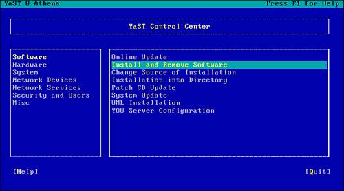
Figure 2.2. The X Windows System’s YaST main menu.
The YaST tool provides command-line shortcuts for accessing the configuration options of the various modules. As an example, you can access the firewall configuration screen by starting YaST, selecting the Security and Users menu, and then selecting the Firewall option. Alternatively, you can go directly to the firewall configuration routines by invoking YaST with the “firewall” command-line parameter. The man pages for yast2 discusses the -list option, which, when invoked, reveals a list of the shortcuts to the different submenu options. Though at first navigating from the main YaST screen will be more comfortable, quickly accessing what is required directly will become second nature.
NOTE
You can find the man page documents for the non-X terminal version of YaST under the yast2 man pages.
SuSEconfig and YaST are tools bundled with SLES that help you configure and maintain your server. Together, the utilities provide a consistent approach and reduce the chances of a forgotten step when multiple changes are required. Now that you have a basic understanding of the YaST tool, it is time to apply this knowledge to everyday system management.
Adding and Removing Packages
Proper maintenance of the different modules that reside on your system helps ensure the reliability of the services you offer. An important step in the configuration of a server is to ensure that only required packages are installed on a system. This has the dual benefit of minimizing resources consumed as well as reducing the possible exposure to exploits in unused packages that tend to be forgotten and therefore not adequately maintained.
How do you know what minimal subcomponents are required to support the main tasking of your server? As a first approximation, this is handled for you by the YaST utility. YaST and the underlying subsystems maintain a list of interdependencies between different packages. If an attempt is made to install or remove a component that is required by a module you need, YaST will warn you.
Installing a Package
The process of adding and removing packages using YaST is fairly simple. As an example, the following walks through the creation of a Domain Name Services (DNS) server. The first step is to build an SLES server and then install the DNS software. Configuring the DNS service is somewhat more complicated and will be covered in Chapter 8, “Network Services.”
Continuing with the desire to run only applications that are absolutely necessary, install a server with SLES and choose to install a minimum system. This installs SLES, YaST, and a number of other utilities that make the system easier to administer. To convert this base system into a DNS server, you must add the DNS server software (Bind).
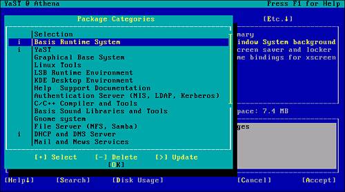
Because the newly installed system is running a base install of SLES, the X Windows System is not available. Sign onto the machine using the root account and start YaST by typing yast at the command line. Figure 2.1 shows the ncurses main menu for the YaST tool. You navigate through the tool by using the tab and arrow keys, and when available, highlighted characters represent Alt-keystroke shortcuts. In Figure 2.1, the Install and Remove Software option has been selected.
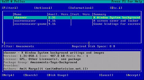
Pressing Enter at this stage brings up the Install and Remove submenu. By default, the selection screen is filtered by RPM groups. Because the leftmost column for these items is blank in Figure 2.3, you know that they are not installed on this system. If an item is already installed on one of your servers, a lowercase i will appear on the left side.
Figure 2.3. YaST installed software filtered by RPM group.
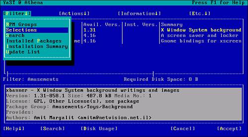
To find the packages already installed on this system, change the filtering option. You can change the filter to show the packages by Selection group by pressing Alt-F and choosing Selections from the drop-down menu, as in Figure 2.4.
Figure 2.4. Changing the Filter setting to present items by choosing Selections.
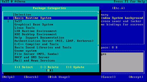
After you choose Selections and press Enter, a window appears showing the package groups currently installed (see Figure 2.5). As you can see from the figure, only the base SLES system and YaST are installed on this system.
Figure 2.5. Installed components for a minimum configuration of SLES.
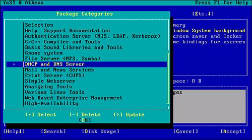
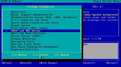
To install the DNS components required, use the arrow keys to scroll down to the appropriate option and press the plus sign (+) or spacebar to select the package (see Figure 2.6). You can then tab over to the OK button or press Alt-O to continue.
Figure 2.6. The DHCP and DNS Server option is selected for installation.
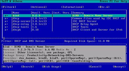
You are then presented with the items contained in the package, as shown in Figure 2.7. If required, it is possible to scroll through these items and remove those not needed. In the current example, simply accept the whole package, select Accept (Alt-A), and continue the installation.
Figure 2.7. YaST installation package subcomponent listing.
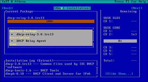
From this stage on, you are prompted for the appropriate media required for the packages selected (see Figure 2.8). If the media is not readily available or if you decide to stop at this point, you can abort the installation by pressing Alt+R. If you do this, the requested changes will not be committed to the current configuration.
Figure 2.8. YaST prompt for the appropriate installation media.
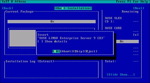
Figure 2.9 shows the progress information of the installation. As each subcomponent is installed, the size, description, and files are displayed.
Figure 2.9. YaST installation progress screen.
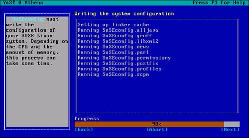
After all the required components are copied to the server, the appropriate changes are made to the configurations files. As explained earlier, YaST delegates these tasks to the SuSEconfig tool. As each subsystem is affected, YaST logs SuSEconfig’s progress, as you can see in Figure 2.10.
Figure 2.10. YaST delegates configuration changes to SuSEconfig.
You have now successfully installed the DHCP and DNS package on the server. Before these services can be used, they must be configured. These tasks will be explained in Chapter 8. We will now investigate how unwanted applications can be removed.
Removing a Package or Subcomponents
The steps required to remove components of the server are similar to those used to install them. In the previous example, you installed the software required for creating a DNS server. At the same time you installed the DNS software, you also installed a DHCP server environment. Due to their interoperability, it is not uncommon to host these applications on the same server. However, since you expect to place this DNS server so that it is accessible from the Internet at large, it would not be prudent to host the DHCP environment on the same server.
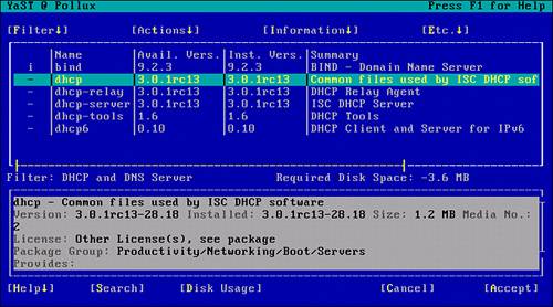
To remove the DHCP components, start YaST and navigate to the Install and Remove Software submenu. Change the filtering option to Selections (as you did during the install phase). In addition to the software listed in Figure 2.5, you now have the DHCP and DNS server package installed, as indicated by the letter I in the left column (see Figure 2.11).
Figure 2.11. Verification that the DHCP and DNS server packages are installed.
To remove the DHCP components, mark the package for update. Highlighting the DHCP and DNS menu option allows you to type a greater-than sign (>) or press the spacebar and select the Update function (see Figure 2.12).
Figure 2.12. The Update option is selected for the DHCP and DNS Server package.
Selecting OK from this screen reveals the list of subcomponents making up the package. This same screen was presented during the install (refer to Figure 2.7). In this case, however, you can select any of the subcomponents for removal. This can be done by entering a hyphen (-) next to the package.
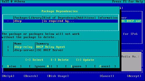
The question of which one to remove first is handled by YaST itself. As components are selected for removal, YaST checks for any dependencies and presents an appropriate warning if necessary. In Figure 2.13, the DHCP common components were chosen first for removal. After you select them, YaST presents a list of the dependent components. As you can see, dhcp-relay and dhcp-server require that the common components be present. By canceling this step and choosing the other dependent packages, you can ensure a clean uninstall.
Figure 2.13. Component removal dependency warning.
After all the appropriate DHCP components have been marked for removal (see Figure 2.14), you can select the Accept option. YaST then proceeds to remove the identified software and invokes SuSEconfig to manage the changes in the system configuration. At this stage, you should now have a minimum system configuration hosting a single network server process: DNS. We will discuss the configuration of DNS in Chapter 8.
Figure 2.14. Identification of components to be removed.
You have seen how YaST can simplify the process of adding and removing application packages on a system. When a system environment is properly configured for its tasking, few changes will be made.
As a system matures and the user community’s use of a machine increases, it is not uncommon for a system to run low on resources. The following section examines how you can add devices to a system to solve some of these issues.
Adding and Removing Hardware
The acquisition stage of a new server should include preliminary growth estimates. Capacity planning is an ongoing process and can usually monitor long-term resource consumption. Eventually, either through aging or through the creation of unexpected projects, servers become resource bound.
When possible, a new server will be purchased, with significantly larger capacity, and the functionality transferred to the new machine. In many cases, however, budget or, more typically, time constraints make this impossible.
The most common resource problem is disk space. As users become accustomed to a system or service, they tend to use it more. They copy their local workstation files to the server for proper backups and disaster recovery purposes. In some cases, an individual or department significantly increases its website with new and improved features. Either way, as system manager, you will be required to increase the system’s capacity.
The following section examines how additional disk space can be added to a system and targeted to a specific solution. It is understood that additional disk space will have backup and disaster recovery implications. These topics will be covered in Chapter 10, “Data Backup and Disaster Recovery.”
Preparations
The most common hardware added to a system is disk space. Other devices you might want to add to your system usually come with vendor-specific instructions for SLES and will not be covered here. Many are peripherals such as scanners, webcams, and audio gear that are not typically incorporated into servers.
For the purpose of this section, we will discuss the concept of a disk as a single physical unit of storage. We will ignore the underlying complexities of how the unit of storage is generated. The “disk” could be simply a single IDE spindle of fixed capacity, or it could be a partition of a larger RAID array managed at the firmware level. In the current discussion, we will treat these as identical in terms of how they are presented to the operating system.
In smaller servers such as a DNS or small web server, it is sometimes simpler to use many of the default install options for SLES. One of the implications of such an installation is that the Logical Volume Manager (LVM) software is not used to configure the environment. LVM allows for the dynamic addition of disk capacity and targets the new disk to specific volume sets on a live system. Though very powerful, such configurations can get very complex and will not be addressed in this section. Additional information on LVM can be found as a series of whitepapers on the SUSE website (http://www.suse.com/en/whitepapers/lvm/lvm1.html).
Before you add a disk device to a system, it is important to know where you are going to target the device. When you’re building a system, it is good practice to separate, on different devices or partitions, various portions of the directory structure. If, at any point, your / partition becomes 100% used, your system will not be able to operate.
Segregation of the major branches of the / directory help mitigate accidental consumption of critical disk space. Typically, the / level directory on your SLES server contains the entries in the following listing:
Athena:~ # ls /
. bin dev home lost+found mnt proc sbin sys usr
.. boot etc lib media opt root srv tmp var
Athena:~ #
When you are building a server (see Chapter 1, “Installing SUSE LINUX Enterprise Server”), you have the opportunity of allocating these directories to different locations. On a simple one-disk device system, the default install splits the volume into a swap and a / partition. A more robust approach would be to further partition the single volume into distinct areas to contain the more volatile directory structures. On servers that allow end-user content, placing the /home (user files) and /srv (web content) directories on their own device will balance disk consumption across multiple volumes. If individual devices are not available, placing /home and /srv in separate partitions is still a good idea. The segregation will prevent consumption on one partition from impacting the other. Though you can minimize the risks of a disk-full event through quota management, making the system failsafe is simply the smart thing to do.
Adding a Disk
In our example, a disk will be added to the web server Athena. The current web server will be asked to store a large number of corporate documents instead of the original contact information pages it was originally designed for. A suggested methodology could be as follows:
![]() A secondary disk is purchased.
A secondary disk is purchased.
![]() A valid full backup of your system must be performed.
A valid full backup of your system must be performed.
![]() The disk must be physically added to the machine.
The disk must be physically added to the machine.
![]() A valid partition table must be created on the disk.
A valid partition table must be created on the disk.
![]() The partition(s) must be formatted.
The partition(s) must be formatted.
![]() The formatted partitions must be made live.
The formatted partitions must be made live.
![]() Data must be transferred to the new disk space.
Data must be transferred to the new disk space.
![]() Reboot and sanity checks are performed.
Reboot and sanity checks are performed.
![]() User access is restored.
User access is restored.
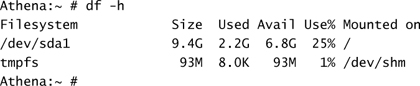
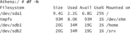
The backup of the system is important because a number of steps in this process could lead to significant data loss or an unbootable system. The physical installation of the disk hardware is machine and interface dependent and will not be covered here. Before the system is shut down, it is important to know the configuration of the disk(s) currently in use on the server. You can accomplish this by using the df command or by looking at the /etc/fstab file:
Or
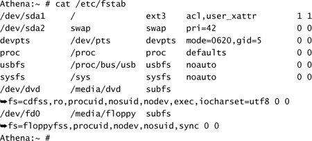
From these listings, you can see that there appears to be only one SCSI disk in the system (sda), and it is split into two partitions—namely, / and a swap partition. When the new disk is added, it is given a unique SCSI ID, in this case, 1, and will appear as the second SCSI disk in the system, sdb. Had we used an IDE-based system, the disks would appear as hda and hdb, respectively.
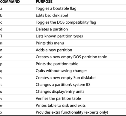
The first procedure is to decide on the low-level configuration of the disk. A partition table contains information on how the disk is subdivided. The simplest way to create a partition table is to use the fdisk utility. You invoke this tool at the command line by using the fdisk verb, followed by the target device name, as shown in Listing 2.1. It is crucial to ensure that you point this utility to the proper device. Failure to do so can result in the corruption of the partition table on an existing device. Detailed information on this utility can be found in the man pages. Once this verb is invoked, the menu m command can be used within fdisk to list the set of internal commands. The possible values available at this time are shown in Table 2.1.
Table 2.1. The fdisk Internal Command Set
WARNING
A properly configured and intact partition table is mandatory for a system to function. It is best to be overly paranoid at this stage and triple-check what you are doing. A mistake here can make your server a boat anchor and set you back a considerable amount of time. Ensure that you have a proper disaster recovery plan and have valid backups before going any further.
The following will create a proper partition table for the new disk being added:
Step 1: Look at the existing partition table.
It is not expected that a new disk will contain a valid partition table. If it does, it may be an indication that you have pointed the utility at the wrong volume or you may be using a disk containing data that could be accidentally destroyed. At the console prompt, type fdisk followed by the name of the new volume (sdb):
Athena:~ # fdisk /dev/sdb
Device contains neither a valid DOS partition table, nor Sun,
SGI or OSF disklabel Building a new DOS disklabel.
Changes will remain in memory only, until you decide to write
them. After that, of course, the previous content
won’t be recoverable.
The number of cylinders for this disk is set to 5221.
There is nothing wrong with that, but this is larger than
1024, and could in certain setups cause problems with:
1) software that runs at boot time (e.g., old versions of LILO)
2) booting and partitioning software from other OSs
(e.g., DOS FDISK, OS/2 FDISK)
Warning: invalid flag 0x0000 of partition table 4 will be corrected by w(rite)
Command (m for help):
Print out a copy of the current partition table for this disk:
Command (m for help): p
Disk /dev/sdb: 42.9 GB, 42949672960 bytes
255 heads, 63 sectors/track, 5221 cylinders
Units = cylinders of 16065 * 512 = 8225280 bytes
Device Boot Start End Blocks Id System
Command (m for help):
The print command reveals a device with no preexisting partition table. You can now proceed and subdivide the disk. In this case, a partition will be created to contain the user’s home directories (/home) and another partition to hold the root directory for the web content folders (/svr). For this purpose, subdivide the disk in two roughly equal halves.
Step 2: Create the partitions.
Use the n verb in fdisk to create a new primary partition. It is essential to create proper Linux-specific entries in the partition table and define the partition types. Failure to do so may generate a scenario in which the disk thinks a partition is vfat but the formatting of the structure is ext3. This will cause confusion for the kernel and possibly data loss.
NOTE
The original specification for partition tables allowed a single device to contain up to four partitions. In some instances, such as restricting access to structures, more than four partitions are desirable.
Extended partitions allow for the creation of additional partitions, within a pre-existing partition. When created, the last primary partition can be subdivided into a number of subunits. Each subpartition can then be presented to the operating system and recognized as a real partition.
Adding extra layers of complexity should be discouraged. Large-capacity drives are relatively inexpensive. It is recommended that additional partitions be provided by additional devices instead of using extended partitions.
The software indicates the geometry of the disk. In this case, split it roughly in half:
Command (m for help): n
Command action
e extended
p primary partition (1-4)
p
Partition number (1-4): 1
First cylinder (1-5221, default 1): 1
Last cylinder or +size or +sizeM or +sizeK (1-5221, default 5221): 2600
Command (m for help): n
Command action
e extended
p primary partition (1-4)
p
Partition number (1-4): 2
First cylinder (2601-5221, default 2601):
Using default value 2601
Last cylinder or +size or +sizeM or +sizeK (2601-5221, default 5221): Using default value 5221
Command (m for help):
It is always a good idea to double-check the configuration. This way, you can verify that the type designation for each partition is correct. The partitions are being added to the system to contain standard Linux files. Hence, a type ID of 83 (Linux) is correct. Had you been adding RAM to the system and were required to change the amount of available swap space, you would need to use the type command to change the partition type ID to 82 (Linux Swap). A list of the available partition types can be generated by using the l command shown in Table 2.1.
Though it is possible to place a filesystem of one flavor into a partition marked as a different partition type, doing so is not recommended. By creating the appropriate type of partition, you can verify the nature of a partition before it is mounted into a live system. Mounting a partition with an inappropriate filesystem type will result in data loss and corruption. This is especially true if the mount forces a filesystem check and discrepancies in formatting are interpreted as corruption.
Step 3: Confirm the selections.
Print out the current in-memory version of the partition table before committing the changes to the physical device:
Command (m for help): p

Command (m for help):
Now that you have the geometry of the disk as you want it, you need to write the information back to the disk.
Step 4: Commit the new partition information.
The in-memory configuration of the partition table is applied to the physical device through the w (write) command:
Command (m for help): w
The partition table has been altered!
Calling ioctl() to re-read partition table.
Syncing disks.
Athena:~ #
The last procedure that is required before the disk can be brought online for content is to prepare the partitions for the operating system. To do this, you must configure the partition to obey certain rules governing file structures and the way files are accessed and written. You perform this task by creating a file system on the disk. In the Windows and DOS world, this is known as “formatting.”
Step 5: Make a file system for the /home directory structure.
For this step, use the mkfs command. A number of different file systems are available for SLES; they can be found in the man pages. Choosing the correct one for your situation depends on individual corporate policy. For the sake of this example, use ext3.
A good practice is to apply a label to the device partition as you apply the file system. This approach has several benefits. In this case, it could be used to confirm that you allocated the appropriate partition to the intended target before restoring any data.
It is also possible to define a number of additional characteristics for your filesystem. One important consideration is the number of files you expect the partition to contain. Each physical file on the disk is referenced through a structure called an inode. When a filesystem is created, the number of inodes created is based on typical average file size and the size of the partition. If, in your situation, you know that there will be a significant number of very small files, you may need to force a specific inode count. More information on specifying the number of inodes can be found in the man pages for your specific filesystem.
Athena:~ # mkfs.ext3 -L HOME -v /dev/sdb1
mke2fs 1.34 (25-Jul-2003)
Filesystem label=HOME
OS type: Linux
Block size=4096 (log=2)
Fragment size=4096 (log=2)
2611200 inodes, 5221117 blocks
261055 blocks (5.00%) reserved for the super user
First data block=0
160 block groups
32768 blocks per group, 32768 fragments per group
16320 inodes per group
Superblock backups stored on blocks:
32768, 98304, 163840, 229376, 294912, 819200, 884736, 1605632, 2654208,
4096000
Writing inode tables: done
Creating journal (8192 blocks): done
Writing superblocks and filesystem accounting information: done
This filesystem will be automatically checked every 39 mounts or
180 days, whichever comes first. Use tune2fs -c or -i to override.
Athena:~ #
Step 6: Make a file system for the /srv directory structure.
Athena:~ # mkfs.ext3 -L WEB -v /dev/sdb2
mke2fs 1.34 (25-Jul-2003)
Filesystem label=WEB
OS type: Linux
Block size=4096 (log=2)
Fragment size=4096 (log=2)
2632672 inodes, 5263295 blocks
263164 blocks (5.00%) reserved for the super user
First data block=0
161 block groups
32768 blocks per group, 32768 fragments per group
16352 inodes per group
Superblock backups stored on blocks:
32768, 98304, 163840, 229376, 294912, 819200, 884736, 1605632, 2654208,
4096000
Writing inode tables: done
Creating journal (8192 blocks): done
Writing superblocks and filesystem accounting information: done
This filesystem will be automatically checked every 29 mounts or
180 days, whichever comes first. Use tune2fs -c or -i to override.
Athena:~ #
The final processes required to incorporate the new device and partitions into the server demand a significant amount of attention to detail. They also require a significant amount of scheduled downtime. To minimize the service outage, you can perform a number of steps before you take down the system.
First, you can create temporary mount points for the new partitions. They are renamed /home and /srv while the system is in single user mode. In addition, you can prepare a new version of fstab to mount the new partitions on their proper mount points. This way, you can test the fstab file while the system is in single user mode and not have any surprises when the system reboots.
Step 7: Create temporary mount points and check permissions.
Athena:~ #
Athena:~ # cd /
Athena:~ #
Athena:/ # mkdir /new_home
Athena:~ #
Athena:/ # mkdir /new_srv
Athena:~ #
Athena:~ #
Athena:/ # ls -ld *home* *srv*
drwxr-xr-x 7 root root 4096 Jan 20 08:23 home
drwxr-xr-x 2 root root 4096 Jan 20 10:40 new_home
drwxr-xr-x 2 root root 4096 Jan 20 10:40 new_srv
drwxr-xr-x 4 root root 4096 Jan 5 04:42 srv
Athena:/ #
The permissions shown here are correct for files in the root of the filesystem. Users will need read access to the directories. Write access will be granted into subdirectories and below. For the /home structures, users will have write access to their $HOME directory. In the /srv structures, users will be granted access based on the websites they maintain.
Step 8: Clone and add appropriate lines to /etc/fstab.
Clone the fstab file using the cp (copy) command:
Athena:/ # cp /etc/fstab /etc/new_fstab
Add the new device partitions, their target mount points, their filesystem types, and some default attributes to the new_fstab file. You can do this in any text editor, such as vi.
![]()
Step 9: Move to single user mode.
The next step requires that you remove all user access to the file system. This step prevents loss of data in the case of users actively changing content on the server during the switchover. It also has the added benefit of releasing the files used by the web services in the /srv structure. The simplest method for removing all but console access is to bring the system down to single user mode by changing the current runlevel.
Runlevels are covered in more detail in the next chapter. In the current context, a multiuser server is typically at runlevel 3 or runlevel 5 if the X Windows System is active. In single user mode, runlevel 1, the system will have only a minimum number of services running and no interactive sessions other than console access.
For maintenance purposes, the server needs to be transitioned to runlevel 1. You can achieve this by using the init command:
Athena:/ # init 1
NOTE
Bringing the machine down to single user mode disables all network services on the server. You need physical access to the console environment to continue on from this point.
You can also query the current runlevel of a server by using the runlevel command. The who -r command indicates the current runlevel as well as the previous state.
As an additional precaution, remove the server’s network cable from the NIC. If the machine has multiple NICs, ensure that they are labeled and associated with the appropriate card before you remove them. When you are ready to bring your machine back online, you will want to have a few moments for a sanity check on the work performed.
USER MANAGEMENT
You can rest assured that the user community, especially in the case of an Internet-facing web server, will be waiting to pounce on services, even within the downtime window. Any difficulties encountered during the rebuild will generate distracting phone calls from irate users. It is a good idea to take an extra few minutes to check everything first before you reconnect the server to the real world.
Step 10: Switch directories.
This step must be completed in a systematic fashion to ensure that no information is lost and with a minimum amount of downtime. When the system is in single user mode, you must reenter the root password at the console prompt. When you are logged on, you are ready to do the following:
a. Rename the current directories to a backup version and move the prepared mount points to the appropriate names:
Athena:/ # cd /
Athena:/ # mv /home /old_home
Athena:/ # mv /srv /old_srv
Athena:/ # mv /new_home /home
Athena:/ # mv /new_srv /srv
b. Back up the active fstab and move the new one into position:
Athena:/ # mv /etc/fstab /etc/old_fstab
Athena:/ # mv /etc/new_fstab /etc/fstab
c. Mount the new disk partitions and attach them to the mount points. For this, you use the mount command with the -a parameter. This forces all partitions in /etc/fstab to be mounted. This emulates the state of the mount points after a clean reboot. The mount command used here should be the following:
Athena:/ # mount -a
d. Check to see everything is mounted properly:

Notice the addition of the /home and /srv entries as individual entities and that they both represent 20GB of disk space each.
Step 11:Move the data.
Move the data from the old_ directories to the new disk space:
Athena:/ # cd /old_home
Athena:/home # tar cf - * | ( cd /home ; tar xfp -)
Athena:/ # cd /old_srv
Athena:/home # tar cf - * | ( cd /srv ; tar xfp -)
You have completed the migration of the data from a directory structure to individual mount points associated with the original names. You are now ready to reboot.
Step 12: Reboot and perform sanity checks.
All the work has been completed at this stage. You now need to confirm the behavior of the system after a restart. This step validates that you did not perform a manual task that is not reflected in the system’s normal startup procedures. It also provides a clean shutdown and reinstates the machine to its operational runlevel.
At the console prompt, type reboot:
Athena:/ # reboot
After your system has rebooted, ensure that the new versions of /srv and /home reflect the new configuration. Because they are now mount points instead of traditional subdirectories of /, a df command should show a value for the amount of available disk space for each mount point. An additional quick check would be to test services that depend on the contents that were migrated:
In one of the preceding steps, you removed the network cables from the server. In some instances, the network environment will not initialize properly without live network cables connected to each NIC. To test, you may need to connect to a test network or simply to a laptop with a crossover cable. This should provide the appropriate signals for the card to initialize properly. You may have to restart the network services before continuing with testing. You accomplish this by rebooting the server or, more gently, by issuing the following command:
Athena:/ # /etc/init.d/network restart
In the case of Athena being a web server, checking the default server web page as well as accessing a few user public_html directories should suffice. This would verify that the Apache service found both environments and that the permissions associated with the locations are correct. Secondary checks should include testing the users’ publishing access to the server through FTP or Samba shares. At this point, you can place the machine back in service. Users should be able to connect to their environment, and all service should be running.
Changing Network Configuration
There are several reasons why you might need to change the network configuration of your server: Your company has changed ISPs, and the server is moving from your intranet to the Internet are possible scenarios.
One of the more frequent reasons is that you have built your server in a test environment behind a firewall. Servers are typically built from original distribution CDs that, over time, become outdated. This has the drawback of generating a first cut of the machine that could present several critical vulnerabilities to the network.
It is essential to mitigate the exposures before the machine can be compromised. As we will see in Chapter 12, “Intrusion Detection,” detecting breaches on a server requires having a proper uncompromised image of the system environment. If the machine is exploited before the snapshot has been taken, you may never expose the threat. Building servers behind a paranoid NAT-capable firewall provides additional protection while the system is vulnerable.
Network Parameters
Typically, a machine relies on four main items to enable it to have conversations on a network: a TCP/IP address, subnet mask, routing address, and name server information. Additional information such as the network domain name and domain search order facilitate name resolution but are not essential locally within the server.
In the workstation world, much of this information is provided by DHCP. Servers are usually configured with static information to provide more control over their access and their behavior. In many cases, servers accept connections on specific ports, have a conversation, and close the port. Servers typically do not initiate conversations.
Communications within a subnet depend on a machine’s address residing within a common address space defined by a mapping of the TCP/IP subnet and the associated subnet mask. If the matching bit patterns are compatible and machines are on a common network segment, conversations are possible. As an example, machines present behind a NAT firewall are often given a network subnet in the 192.168.x.0 with a network mask of 255.255.255.0, where the NAT device is usually 192.168.x.1. Servers and workstations behind the device are able to communicate with each other using bare TCP/IP addresses without the need to define a gateway address or a name server.
A default gateway, or routing node address, is required only if the machine in question requires access to other machines outside the current network subnet. This is true for answering to conversations initiated outside the current subnet as well. Though a packet can reach a server from the other side of the routing node, the return packets require a hand-off address if the outbound target TCP/IP address is not within the server’s own subnet space.
Domain name, domain name search order, and DNS server definitions are all related to the way machines resolve human-legible addresses back into network addresses. They provide the opportunity of managing outbound conversations.
Using YaST to Manage the Network Configuration
YaST provides a graphical method for modifying network settings. When changes are made, YaST ensures the necessary updates are made to the appropriate files throughout the system. You can invoke the X Windows System version by clicking on the YaST icon in the menu system or by invoking yast2 from the command line. You can also use the LAN shortcut with either yast or yast2 to go directly to the network setup menu.
DEMILITARIZED ZONES (DMZS)
A DMZ is a network that is surrounded on all sides by firewalls. This prevents any traffic from reaching the machines within the DMZ unless they are specifically allowed.
Permissions for TCP/IP conversations to traverse the firewalls are called firewall rules. These rules require that the source and target TCP/IP addresses, the protocols, and ports be specified for each allowed conversation.
Typically, a firewall is placed between a hostile network (usually the Internet) and Internet-facing machines such a mail, DNS, and web servers. Traffic within the DMZ is controlled with the local server firewall configuration.
The DMZ machines are in turn considered hostile hosts and are further separated from a company’s network by yet another series of firewalls. This back-end firewall controls what, if any, protocols are allowed to access the production network environment. Often web servers require access to a production database. This database server should be in a separate DMZ to further protect its content.
In short, a DMZ is an implementation of a layered defense. The more layers of properly configured protection you have, the better you are protected.
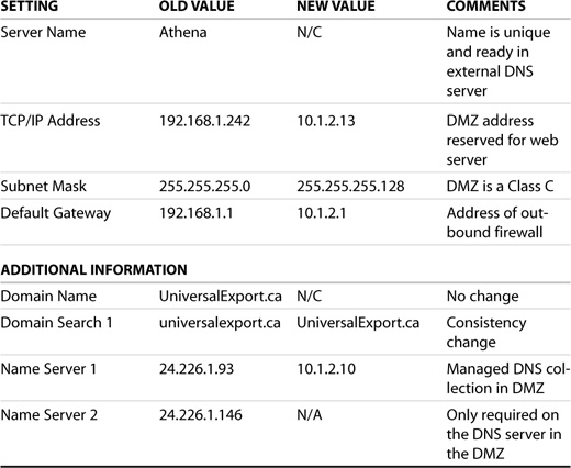
Before proceeding, you need to know what you are changing, why you are changing it, and the new values for each parameter. Table 2.2 shows a typical network configuration change form.
Table 2.2. Athena Network Configuration Worksheet
The current configuration screen for a server is shown in Figure 2.15. The upper portion of the window shows that there are no unconfigured network cards. The lower portion shows the network cards that have been previously configured and available for changing.
Figure 2.15. Initial LAN configuration screen in YaST.
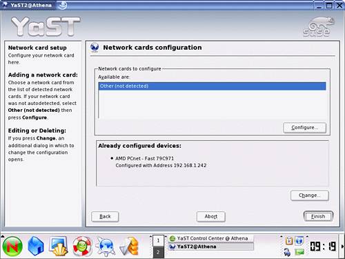
Clicking the Change button brings up an intermediary window showing the network cards resident within the machine. In the case of servers with a single NIC, the required card is already highlighted, and you can select Edit to continue with the reconfiguration. If your server has additional interfaces, select the one you want to change; then select the Edit button.
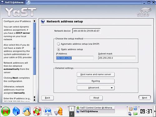
You are presented with a window similar to that shown in Figure 2.16. The basic TCP/IP information is there for you to edit. At this stage, you can replace the configured IP address with the server’s new permanent address. Ensure that the appropriate subnet mask is also configured.
Figure 2.16. YaST network configuration window.
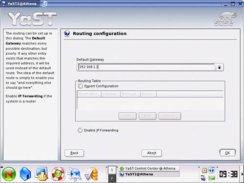
Selecting the Routing button presents you with the window shown in Figure 2.17. At this stage, complex routing is not required, and you can simply update the unique address for the current default gateway and replace it with the DMZ firewall address as per Table 2.2. The firewall will filter outbound packets to ensure that they are of the appropriate type over known and allowed protocols. Select OK to accept the change and return to the network configuration window.
Figure 2.17. YaST Default Gateway configuration screen.
The final step in the reconfiguration is to define the Domain Name Services accessible from this machine. In some configurations, it is acceptable to have servers able to resolve names Internetwide. In most circumstances, having tight control over name resolution can quickly help you identify an improper configuration, an unidentified requirement or, more importantly, suspicious traffic that might indicate a compromised server.
By pointing name resolution to a single DNS server that does not look beyond itself for name resolution, you have better control over the resulting conversations. In the case of the sample web server, it responds to conversations directly by IP address through ports initiated by requests outside the firewall. The restrictive DNS configuration in the DMZ will prevent any unexpected server-generated conversations from name-resolving hosts and potentially exposing data externally. You can achieve the same effect through a local hosts file and not specifying a DNS server. The current approach, however, allows for consistency within the DMZ and a single location to maintain for updates.
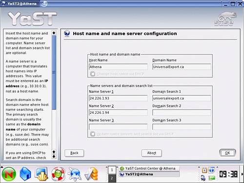
You can incorporate the changes identified in Table 2.2 by making the appropriate modification to the window presented by clicking the Host Name button. You can see an example of the configuration window in Figure 2.18. After you have completed modifications, click OK.
Figure 2.18. Host name and name server configuration.
You can apply the combined changes to the system by selecting the Next button on the Network Configuration screen and the Finish button on the resulting network Card Configuration window.
YaST then applies the updates to the appropriate files across the server. YaST will then automatically restart your network services to incorporate the change. You should then be in a position to test access to the server from the new network as well as the name resolution restrictions incorporated in the design.
Summary
Updating servers can be quite a complex task. It is, however, mandatory in order to maintain a secure and robust environment. This chapter touched on a number of the more common configuration tasks. We explored examples of
![]() Navigating the two interfaces available for the YaST tool
Navigating the two interfaces available for the YaST tool
![]() Adding and removing software modules
Adding and removing software modules
![]() Adding additional storage resources
Adding additional storage resources
![]() Maintaining the network interface
Maintaining the network interface
SUSE LINUX provides the YaST tool that can be leveraged to make server configuration tasks easier and consistent across an enterprise. The YaST utility is provided in both an X Windows System and ncurses interface, allowing the use of this tool on even the most minimal of configurations. In the following chapters, YaST will be the tool of choice used to maintain the various services available on SUSE.
This chapter also explored the various steps required to add additional storage capacity to a server. In doing so, we covered a number of topics ranging from disk partitions, filesystems, mount points, and permissions. In moving data from old directories to the new mount points, we have, in essence, covered methods for backing up data and preserving directory structures and permissions.
One of the most important concepts introduced in this chapter revolves around the network connectivity of servers. We introduced the concept of a secure environment for servers to prevent compromises as we build them. We touched on the importance of keeping systems offline as we are maintaining them. The concept of a DMZ was introduced as a standard practice for securing environments exposed to potentially hostile networks.