This chapter covers the following topics:
This chapter covers the basics of video encoding and decoding and describes most of the algorithms used by standard video codecs. In addition to the encode/decode process, this chapter describes the preprocessing and post-processing used by most endpoints. Left out of this chapter is the Real-time Transport Protocol (RTP) packetization process, which is covered in Chapter 4, “Media Control and Transport.”
When evaluating the efficiency of a video codec, there is one primary criterion: the quality at a given bit rate. Most video conferencing endpoints negotiate a maximum channel bit rate before connecting a call, and the endpoints must limit the short-term one-way average bit rate to a level below this negotiated channel bit rate. A higher-efficiency codec can provide a higher-quality decoded video stream at the negotiated bit rate. Quality can be directly measured in two ways:
By visually inspecting the decoded video
By using a formula that mathematically compares the decoded video to the original video sequence
Visually inspecting the output of a decoder is a perceptually qualitative process and is generally useful only for side-by-side comparisons between different codecs. The quality level from a subjective standpoint typically ranges from “sub-VHS quality” at the low end to “DVD quality” at the high end. It is important to note that this perceptual quality incorporates the size of the image, the frame rate, and the spatial quality of the video. Business-oriented video conferencing endpoints can achieve VHS quality at 384 kbps, with 352×288 resolution and 30 frames per second (FPS). DVD quality generally requires a higher resolution of 640×480 at a frame rate of 30 FPS and no significant loss of video spatial quality. DVDs use the MPEG-2 codec and are limited to a bit rate of 10 Mbps, whereas VHS tapes encode video in an analog format.
A more objective measure of codec performance is the peak signal-to-noise ratio (PSNR). It is a measure of how much a decoded image with pixel values PO(x,y) deviates from the original image PI(x,y). The PSNR is determined by first calculating the mean squared error (MSE) between the two images:
Then, the PSNR is the log ratio of the largest possible pixel value to the MSE, measured in dB:
Although this formula is an objective calculation, it does not necessarily correlate to the quality of an image as perceived by the human visual system. Nonetheless, it is useful as a tool to compare different codecs.
To minimize the end-to-end delay of the video streams, video codecs used for video conferencing must operate in a mode that supports low delay. As a result, these codecs might not be able to take advantage of extended features or special coding methods commonly used when compressing material for one-way viewing, such as the encoding used for DVDs. Three of these features that are not available to video conferencing codecs include B-frames, multipass coding, and offline coding.
B-frames allow a codec to compress a frame using information from a frame in the past and a frame in the future. To compress a B-frame, the encoder must first process the future referenced frame, which requires the encoder to delay the encoding of the B-frame by at least one frame. Because of the one-frame delay, most codecs for video conferencing do not implement B-frames.
Multipass coding is the process of encoding a stream multiple times in succession. After performing the first pass, the encoder analyzes the result and determines how the encoding process can be altered to create the same quality encoded video at a lower bit rate. A multipass codec typically re-encodes a bitstream at least once, and possibly twice. Obviously, this sort of multipass processing is not possible with a codec used for video conferencing.
Offline coding is simply the process of encoding a video sequence in non-real time using computationally intensive offline hardware to achieve a lower bit rate with higher quality. Offline coding can provide a significant boost to codec efficiency, particularly for the more complex codecs such as H.264. However, this method is not available for video conferencing endpoints.
When evaluating a codec to use in a video conferencing product, it is important to observe the quality of a decoded bitstream that was encoded without any of the prior methods. When using encoded/decoded test video sequences for evaluation, make sure that those test sequences were created as follows:
Without B-frames
Without multipass coding
In real time rather than offline
When two endpoints establish a video connection, they must negotiate a common supported format. This format includes the codec algorithm and parameters of that algorithm, such as frame rate and bit rate.
Codec specifications generally define a wide breadth of features that can be used to encode a video sequence. Some of the more complex features might require additional resources, such as CPU power and memory. In addition, more CPU power is needed when decoding video with higher frame rates, image sizes, and bit rates.
Therefore, to facilitate decoders with fewer available resources, the codec specifications often define profiles and levels:
Profiles define a limited subset of features that will be used by the encoder. Fewer features in the bitstream will reduce the resources needed on the decoder, and the decoder complexity. As an example, some codec profiles prohibit B-frames, which normally require additional frame buffer memory and CPU processing.
Levels define limitations on parameter ranges, such as image size, frame rate, and bit rate.
Two endpoints in a video conference negotiate a maximum video bit rate before connecting. Video codecs can generate bitstreams ranging from 64 kbps to 8 Mbps and more. Higher bit rates consume more network bandwidth but provide greater video quality and frame rate. A bit rate of 384 kbps is considered “business quality” for conferencing systems. However, as high-definition TV (HDTV) video conferencing becomes more prevalent, the definition of business quality might evolve to mandate HDTV resolution, and higher bit rates approaching 4 Mbps.
After the conference participants choose a video bandwidth, the endpoints choose a nominal frame rate, which is also negotiated between the two sides during call setup. For desktop PC systems with limited CPU power, the nominal frame rate is often 15 FPS, whereas higher-end standalone video conferencing systems can generally support nominal frame rates of 30 FPS. However, during the call, the actual frame rate might change over time, because the encoder must constantly trade off between bit rate, frame rate, and quality. When the video camera on an endpoint captures a high degree of motion, the encoder can maintain the same frame rate and quality by increasing the bit rate. However, because the endpoints have predetermined the maximum allowable bit rate, the encoder must instead keep the bit rate constant and lower the frame rate or quality.
Video codecs generally support a standard-size video frame format called Common Intermediate Format (CIF). The CIF format is 352×288, and other standard sizes include variations of the CIF format, shown in Table 3-1. In addition to CIF, the two other common sizes are Quarter-CIF (QCIF, 176×144) and 4xCIF (4CIF, 704×576). For all CIF variations, each pixel has an aspect ratio (width to height) of 12:11. The codec standards often refer to pixels as pels and may define a pel aspect ratio. For the CIF size of 352×288, the overall aspect ratio of the entire frame is 4:3. The total aspect ratio of a Sub-Quarter CIF (SQCIF) frame is 16:11.
Chapter 7, “Lip Synchronization in Video Conferencing,” describes the formats for standard-definition (SD) and high-definition (HD) video formats. Some high-end video conferencing systems, such as telepresence endpoints, support HD video cameras. These cameras provide video images with a higher resolution than the traditional SD formats (NTSC/PAL/SECAM) allow. SD and HD differ in several aspects:
Aspect ratio—. Aspect ratio refers to the ratio of width to height of the video frame. SD typically has a 4:3 aspect ratio, whereas HD has a 16:9 aspect ratio.
Resolution—. HD cameras provide a video signal with a resolution as high as 1920×1080 pixels, whereas the maximum resolution of an NTSC SD signal is 704×480.
Interlaced or progressive—. HD cameras may provide video signals that are either interlaced or progressive. When specifying the resolution or frame rate of an HD camera, it is common to add a p or an i at the end of the specification to denote interlaced or progressive. For instance, the format 720p60 corresponds to a video signal with a size of 1280×720 pixels, progressively encoded at 60 FPS. The format 1080i50 is 1920×1080 pixels, interlaced, with 50 fields (or 25 frames) per second. Most often, the frame rate is left out of the notation, in which case it is assumed to be either 50 or 60. Also, a description of an HD signal may specify a frame rate without a resolution. For instance, 24p means 24 progressive frames per second, and 25i means 25 interlaced frames per second.
Much like interlaced processing, support for the higher resolution of HD encoding is limited to certain codecs, and often to specific profiles and levels within each codec.
The color and brightness information for pixels can be represented in one of several data formats. The two common formats are RGB and YCbCr. The RGB format represents each pixel using values for the red (R), green (G), and blue (B) additive color components. The YCbCr format represents each pixel using the brightness value (Y), along with color difference values (Cb and Cr), which together define the saturation and hue (color) of the pixel. The brightness values comprise the luminance channel, and the color difference values comprise the two chrominance channels. The chrominance channels are often referred to as chroma channels.
The video codecs discussed in this chapter process images in the YCbCr color format and therefore rely on the video-capture hardware to provide frame buffers with YCbCr data. If the capture hardware provides video data in RGB format, the encoder must convert the RGB frames into YCbCr before beginning the encoder process. This process is called colorspace conversion.
Video encoders process data in YCbCr format because this format partitions the most important visual information in the Y channel, with less-important information in the Cb and Cr channels. The human visual system is more sensitive to degradation in the luminance channel (Y) and is less sensitive to degradation in the chrominance channels. Therefore, the data pathways in the encoder can apply high compression to the Cr and Cb channels and still maintain good perceptual quality. Encoders apply lower levels of compression to the Y channel to preserve more visible detail. Codecs process YCbCr data that consists of 8 bits in each channel, but some codecs offer enhanced modes that support higher bit depths.
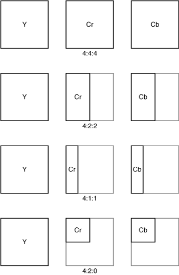
The first operation of the encoder is to reduce the resolution of the Cr and Cb channels before encoding, a process known as chroma decimation. Figure 3-1 shows different formats for chroma decimation.
The original, full-resolution frame of source video from the camera is represented in a format called 4:4:4. Each 4 represents a full-resolution channel, and 4:4:4 corresponds to full resolution of the Y, Cb, and Cr channels. 4:2:2 represents full resolution in the Y channel, with half the resolution in the horizontal direction for Cb and Cr. 4:1:1 represents a video image with a quarter of the resolution in the horizontal direction for Cb and Cr, with full resolution for Y. The codecs discussed in this chapter use a format known as 4:2:0, which departs from the usual nomenclature and represents an image with half the resolution in both horizontal and vertical directions for Cb and Cr, with full resolution for Y.
Whereas the 4:2:0 chroma decimation from 4:4:4 to 4:2:0 provides immediate reduction in the source bit rate without a significant degradation in quality, in two instances it is beneficial to retain higher chroma resolution (4:4:4 or 4:2:2):
The encoder should retain 4:4:4 or 4:2:2 resolution if the video stream will undergo further processing at a professional studio. Studio processing demands the highest resolution for chroma channels.
The original 4:4:4 resolution should be retained if the video signal will be used later for chroma keying. Chroma keying is a special effect that replaces a specific color in the video sequence with a different background video signal. A typical chroma key video production places a green screen behind an actor and then later replaces the green color with a different background video. The chroma key replacement operation provides the best results if the chroma channels are available at the highest resolution possible, to perform the pixel-by-pixel replacement in areas with a highly complex pattern of foreground and background pixels, such as areas of fine wispy foreground hair.
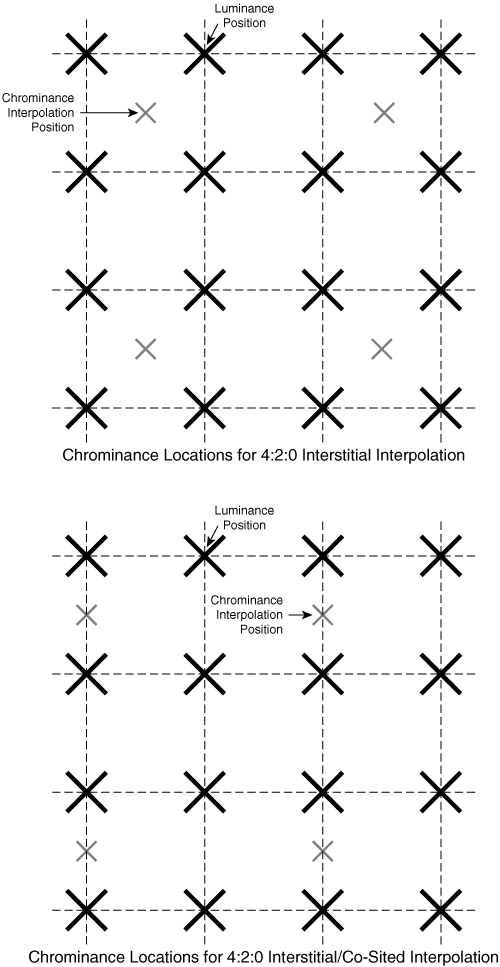
To downsample from 4:4:4 to 4:2:0, the encoder creates reduced-resolution channels for Cb and Cr by interpolating values of Cb and Cr at new locations, relative to the original full-resolution Cb and Cr channels. Codecs for video conferencing use one of two variations of this interpolation, as shown in Figure 3-2.
In the first format, called 4:2:0 interstitial, the interpolation positions are centered at locations that are halfway between two adjacent full-resolution pixels, both horizontally and vertically. In the second format, called 4:2:0 interstitial/co-sited, the interpolation locations are halfway between two pixels vertically and are aligned with original pixel locations horizontally. Table 3-2 shows the 4:2:0 variations used by the standard video conferencing codecs.
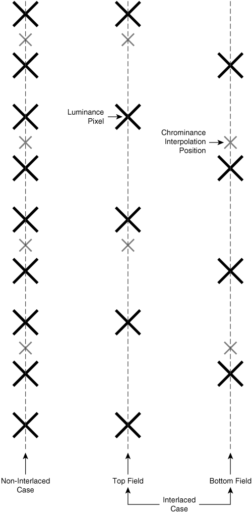
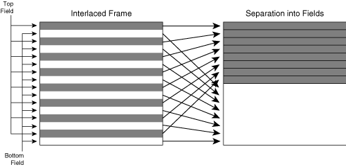
In addition, codecs must use a special variation of 4:2:0 when field coding interlaced video data. Figure 3-3 shows this variation.
For each individual field in an interlaced image, the encoder offsets the location of the chroma interpolation point up or down vertically, depending on whether the field is the top field or the bottom field. As a result, the chroma sampling positions are spatially uniform, both within each field and within the entire two-field frame.
Video coding involves four major steps: preprocessing, encoding, decoding, and post-processing. At the heart of the encoder is a feedback loop that predicts the next frame of video and then transmits the difference between this prediction and the actual frame. Because the encoder uses a recently decoded frame to generate a prediction, the encoder has a decoder embedded within the feedback loop.
Before an image is handed to the encoder for compression, most video conference endpoints apply a preprocessor to reduce video noise and to remove information that goes undetected by the human visual system.
Noise consists of high-frequency spatial information, which can significantly increase the pixel data content, and therefore increase the number of bits needed to represent the image. One of the simpler methods of noise reduction uses an infinite impulse response (IIR) temporal filter, as shown in Figure 3-4.
In this scenario, the preprocessor creates a new output frame by adding together two weighted frames. The first weighted frame is the current input frame multiplied by 0.95. The second weighted frame is the previous output of the preprocessor multiplied by 0.05. This process effectively blurs the image slightly in the temporal direction, reducing background noise. When participants use a noisy video source, such as a webcam, the endpoints can apply a stronger temporal filter by increasing the percentage of the previous frame used in each iteration.
A second function of a preprocessor is to remove information that is generally not perceived by the human visual system. As a result, the encoding algorithm produces a smaller bitstream with less information, but without loss of detail. Preprocessing operations often take advantage of the fact that the human visual system perceives less spatial resolution in areas of the image that contain a high degree of motion. To remove this “unseen” information, the preprocessor can use a spatiotemporal filter to blur an area of the image spatially at locations of high motion. The preprocessor performs this operation on a pixel-by-pixel basis by calculating the difference in value between a pixel in the current frame and the corresponding pixel in the previous frame. If this difference is greater than a threshold value, this pixel is deemed to be in an area of high motion, and the preprocessor can apply blurring to that pixel in the current frame, typically using a spatial low-pass filter.
Even though preprocessing is almost always used by video conferencing endpoints, the decoder is unaware of the process. Because codec specifications describe only how a decoder interprets the bitstream, preprocessing is not within the scope of the standards and therefore is never mentioned in codec specifications. However, to achieve high quality, endpoints generally must implement one or more of these preprocessing steps.
The codecs in this chapter divide the image into 4×4 or 8×8 pixel areas called blocks and then encode each of these blocks one at a time. The decoding process is lossy, meaning that the decoded image deviates slightly from the original image. After the decoding process, the resulting pixel values deviate from the original pixel values somewhat smoothly within each block. However, the pixel deviations might not match up at the boundaries between two adjacent blocks. Such a mismatch in pixel deviations at a boundary causes a visible discontinuity between adjacent blocks, a phenomenon known as block artifacting.
To combat block artifacts, decoders can implement deblocking filters, which detect these block border discontinuities and then modify the border pixels to reduce the perceptual impact of the block artifacts. Deblocking filters can range in complexity from simple to extremely complicated:
At the simple end of the spectrum, a deblocking filter can simply calculate the difference between two pixels at the border of a block. If the difference is above a preset threshold, the post-processor can apply a blurring operation to the pixels on each side of the border.
More complicated deblocking filters attempt to discern whether the discontinuity is due to a block artifact or due to the edge of a real object in the scene. In addition, if the deviations at the boundary are great, the blurring filter can modify pixels at the border and pixels one position farther away from the border pixels.
Unlike preprocessing, encoder specifications usually specify the method of post-processing, because the encoder and decoder use the output of the post-processor to encode/decode the next frame. Because the encoder and decoder must remain in lockstep, they must each use an identical reference frame with identical post-processing.
Video codecs may apply intracoding or intercoding. An intraframe, also called an I-frame, is a frame that is coded using only information from the current frame; an intracoded frame does not depend on data from other frames. In contrast, an interframe may depend on information from other frames in the video sequence.
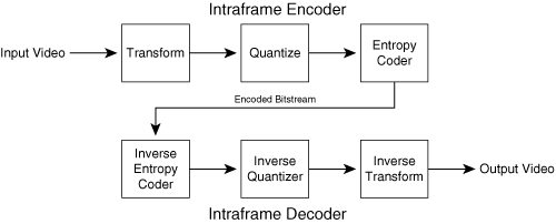
Figure 3-5 shows an overview of intra-image encoding and decoding. The intra coding model consists of three main processes applied to each frame: transform processing, quantization, and entropy coding. Figure 3-5 also shows the corresponding decoder. The decoder provides the corresponding inverse processes to undo the steps in the encoder to recover the original video frame.
Each frame of video data at the input to the encoder is considered to be in the spatial domain, where each pixel occupies an (X, Y) location in the original video frame. The transform process in Figure 3-5 converts a video image from the original spatial domain into the frequency domain. The frequency domain representation expresses the image in terms of the two-dimensional frequencies present in the original image. Table 3-3 lists the transform algorithms used by various codecs.
The encoder divides the image into 8×8 or 4×4 blocks and then applies the transform to each block. The output of each transform is an array of the same size as the input block.
There are two types of transforms:
Discrete cosine transform (DCT)
H.264 integer transform
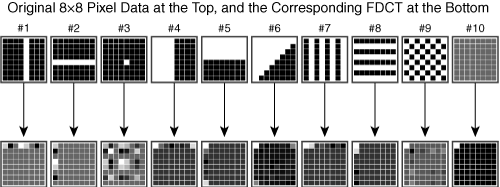
The DCT requires a high degree of internal computational precision, whereas the integer transform consists of simpler mathematical operations that use shifts and additions, which require less precision. The DCT and integer transforms differ mathematically, but they provide the similar function of decomposing the spatial domain into the frequency domain; this direction is referred to as the forward DCT, or FDCT. The inverse DCT (IDCT) performs the reverse transformation, converting frequency-domain values to the spatial domain. Figure 3-6 shows the 8×8 FDCT applied to several original pixel blocks.
The output DCT values are typically in the range [–2048, 2047]. In Figure 3-6, therefore, the outputs of the DCT are shown normalized so that the lowest value is shown as black and the highest value as white. Image patterns 4, 5, and 6 contain less frequency information, because those patterns consist of a single edge. The DCT can represent these patterns with only a few large-magnitude DCT output values.
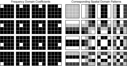
Each position in the transform output array actually corresponds to a pattern of pixels. For the 4×4 transform, the original 4×4 pixel block in the spatial domain can be thought of as a weighted sum of 16 different 4×4 pixel image patterns, each corresponding to a different two-dimensional frequency pattern. Each of these patterns is called a basis function. At the output of the transform, each value in the 4×4 array corresponds to one of these image patterns, and the value itself provides the weighting value applied to the corresponding pattern. Therefore, the values in the output array of the transform are referred to as coefficients. Figure 3-7 shows the frequency pattern corresponding to each coefficient position in the 4×4 transform output array.
The set of blocks on the left shows each possible coefficient location in the transform output array, and the set of blocks on the right shows the corresponding pixel pattern for each coefficient weighting value. In Figure 3-7, all the basis functions have been normalized so that the lowest-valued pixel in each basis function displays as black, and the highest-valued pixel in each basis function displays as white.
The coefficients correspond to frequency patterns as follows:
Coefficients near the upper-left corner of the transform output array correspond to low-frequency patterns; these are patterns that vary slowly over the span of the original input block. In addition, the coefficient at the upper-left corner is referred to as the DC coefficient because it represents the amount of zero-frequency information in the block. This zero-frequency information is just a representation of the average value of all pixels in the block. The notation DC refers loosely to the concept of direct current, which yields a constant voltage. The remaining coefficients are called AC coefficients because they correspond to varying frequency patterns. The notation AC refers loosely to the concept of alternating current, which yields a constantly changing voltage.
Coefficient values near the lower left correspond to frequency patterns containing high vertical frequencies (such as a series of horizontal edges).
Coefficient values near the upper right correspond to frequency patterns containing high horizontal frequencies (such as a series of vertical edges).
Coefficient values near the lower right correspond to frequency patterns containing high horizontal and vertical frequencies (such as a checkerboard pattern or a pattern of diagonal lines).
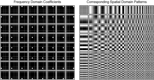
Figure 3-8 shows the basis functions for the 8×8 DCT.
An 8×8 DCT is more efficient when representing large, low-frequency areas, because it needs only a few values from the upper-left corner to represent a larger 8×8 area of slowly varying pixel values. However, the H.264 codec achieves good efficiency with a 4×4 transform.
The transformation from spatial domain to frequency domain facilitates image compression in two ways:
Images encoded in the frequency domain can be encoded with fewer bits. The reason is because typical images consist of mainly low-frequency information, which can be represented with a small number of values from the upper left of the DCT output array. Typical images have little or no high-frequency information, which means that the output of the transform will have values near the lower-right corner that are either small or zero. As described in the section “Entropy Coding,” the number of bits needed to describe this sort of skewed data distribution is less than the number of bits needed to describe the original image in the spatial domain. All codecs in this chapter use this feature.
In the frequency domain, the human visual system is more sensitive to the low-frequency information, represented by values near the upper-left corner of the transform, and is less sensitive to the high-frequency information, represented by the coefficients in the lower right of the transform. Therefore, the encoder can reduce the precision of coefficients representing the high-frequency information without severely affecting the perceived quality of the encoded video. As a result, all codecs represent the lowest-frequency coefficient (the DC coefficient) with a high degree of precision. In addition, the H.264 and the MPEG-4 Part 2 codecs progressively reduce the precision, and therefore the information content, of the coefficients representing the higher frequencies.
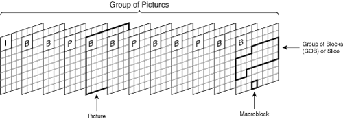
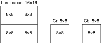
All codecs divide the original image into macroblocks (MB), each of which contains a 16×16 pixel area. The encoder further divides the MBs into 4×4 or 8×8 blocks and then transforms the pixels into frequency domain coefficients. Because the codecs use 4:2:0 chrominance decimation, the pixel area of the Cb and Cr components in an MB will be 8×8 rather than 16×16.
The processing unit in Figure 3-5 that performs the quantization step is the quantizer. Quantization is the process of reducing the precision of the frequency domain coefficients. In the simplest form, the encoder quantizes each coefficient by simply dividing it by a fixed value and then rounding the result to the nearest integer. For instance, the H.261 specification quantizes the DC coefficient by dividing it by 8. By reducing the precision of coefficients, less information is needed to represent the frequency domain values, and therefore the bit rate of the encoded stream is lower. However, because the quantization process removes precision, some information from the original image is lost. Therefore, this process reduces the quality of the encoded image. As a result, codec schemes that use quantization are considered lossy codecs, because the quantization process removes information that cannot be recovered.
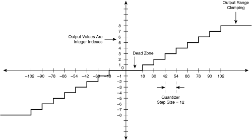
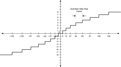
Quantization is performed using an input-output transfer function. Figure 3-9 shows an example.
The transfer function demonstrates several aspects of quantization. The transfer function is always a stairstep, and the fewer the steps, the coarser the quantization. The range of each step on the input (x) axis is called the quantization step size. In Figure 3-9, the quantization step size is 12, which means that each step maps 12 different input values to the same output value. The output values are integer indexes, known as quantization levels.
In the intraframe pipeline, the quantizer operates on output transform coefficients, which may consist of signed numbers. The one exception is the scenario in which the DCT operates on original pixel values; in this case, the DC coefficient represents the average value of all pixels in the original image block and therefore is always positive. However, the quantization transfer function must accommodate both positive and negative values of DCT coefficients.
One characteristic of the DCT is that most codecs define the precision of the coefficient values to be 4 bits more than the precision of the input values. In the case of an intra coded 8×8 DCT block, the original pixels have 8 bits of precision, corresponding to values in the range [0, 255]. The DCT output values have 12 bits of precision, corresponding to values in the range [–2048, 2047]. This level of output precision is necessary to allow the IDCT to recover the original pixels to a value within ±1. Therefore, 12 bits of precision allows encoders to start with the “maximum” level of information content in the frequency domain and then reduce the precision as needed to achieve compression. Because the raw coefficients from the transform function have higher precision than the original image pixels, the quantizer must accommodate this wider range of input values.
Transfer functions generally apply clipping, a process that limits the output of the function to a maximum value. In Figure 3-9, the quantization process clips input values greater than or equal to 102 to an index of 8.
The transfer function might or might not apply a dead zone. Figure 3-9 shows a transfer function with a dead zone, which clamps input values in the vicinity of 0 to 0. This dead zone attempts to eliminate low-level background noise; if a coefficient is close to 0, it is assumed to be background noise and gets clamped to 0.
In some cases, the transfer function can have nonuniform step sizes, as shown in Figure 3-10.
In this approach, the degree of coarseness is proportional to the magnitude of the input value. The principle is that larger input values may be able to suffer a proportionately higher amount of quantization without causing an increase in relative distortion. None of the codecs in this chapter uses nonuniform step sizes; however, the G.711 audio codecs outlined in Chapter 4 uses this method.
Quantization of the transform coefficients may consist of two methods:
Constant quantization—. In constant quantization, the encoder uses the same quantization step size constant for each coefficient in the 4×4 or 8×8 pixel area.
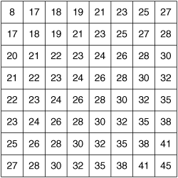
Matrix quantization—. In contrast, matrix quantization applies a different quantization step size to different coefficients. Typically, the matrix quantization process applies a larger step size to higher-frequency coefficients located near the lower right of the transform, because the human visual system is less sensitive to these frequency patterns. Codecs that use matrix quantization generally assign a single quantization level to a block and then use a matrix of numbers to scale the quantization level to the final step size used for each coefficient. Figure 3-11 shows such a matrix of scale factors applied to 8×8 blocks. H.264 and MPEG-4 Part 2 are video conferencing codecs that use matrix quantization.
In most codecs, the bitstream does not specify a step size directly; instead, the bitstream contains a quantization value, often denoted by the variable Q. The encoder and decoder then use this Q value to derive the final quantization step size. A high Q value results in a larger step size and more compression.
The final stage of the generalized encoder is entropy coding, as shown in Figure 3-5. Entropy coding is a lossless codec scheme that seeks to reduce the bit rate by eliminating redundancy in the bitstream. Entropy coding generally operates on a string of one-dimensional data, which means that each two-dimensional quantized coefficient array must be converted into a one-dimensional string.
The entropy of a bitstream is defined as the lowest theoretical average number of bits per symbol needed to represent the information in the bitstream. It also corresponds to the theoretical minimum number of bits per symbol that an ideal entropy coder can achieve. If the bitstream contains n symbols, and the probability of each symbol is P(n), the entropy of the bitstream is calculated using the Shannon entropy formula:
The entropy of a symbol sequence roughly indicates of how well an entropy coder will be able to compress the sequence. Sequences that have lower entropy can be coded using fewer bits per input value. Sequences that have lower entropy are those with a more highly skewed probability distribution, with some input values occurring much more frequently than other values. Such is the case for DTC coefficients, which have probability distributions skewed toward lower values.
Entropy coding generally falls into three categories: run-length coding, variable-length coding, and arithmetic coding.
The simplest form of entropy coding is run-length coding, which achieves compression for streams containing a pattern in which a value in the stream is often repeated several times in a row. When a single value is repeated, it is more efficient for the encoder to specify the value of the repeated number and then specify the number of times the value repeats. A 1-D sequence of quantized DCT coefficients often contains long runs of zeros for the high-frequency coefficients, allowing a run-length coder to achieve a high degree of lossless compression. When the run-length coder specifically codes the number of zeros between nonzero values, this coding scheme is often called a zero-run-length coder.
The decoder expands each run and length pair from the encoder into the original uncompressed string of values.
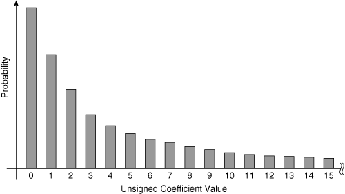
Another form of entropy coding is variable-length coding (VLC). VLC lowers the number of bits needed to code a sequence of numbers if the sequence of numbers has a nonuniform statistical distribution. Figure 3-12 shows a sample statistical distribution for the magnitudes of AC coefficients.
Figure 3-12 shows only the magnitude of the AC coefficient values, because most codecs encode the sign of each AC coefficient separately from the magnitude. The statistical probability distribution is highly skewed, with a much higher probability of encountering lower-valued coefficients.
For these data profiles with skewed probabilities, VLC attempts to represent the high-probability values with shorter bit sequences and the lower-probability values with longer bit sequences. Table 3-4 shows one possible VLC table that can be used in H.264 for AC coefficients. It is a standard table called the Exp-Golomb-coded syntax.
Table 3-4, consisting of input values and output VLC bit sequences, is referred to as a VLC code table. After the encoder constructs the code table, it uses the table to look up the variable-length bitstream of each input value. Instead of using a mathematical algorithm, this process uses a mapping method to map a set of input values into a set of variable-length strings. Therefore, the values in the input set are often referred to as indexes, or symbols, and many of the codec specifications refer to input symbols, rather than input values. Codecs also refer to the VLC table as the symbol code table.
Because the 0 value has the highest probability, it is represented using a single bit, with a bit string of 1. The input symbol 1 is represented using 3 bits, with a bit string of 010. The idea is to use a VLC table that minimizes the average number of bits per symbol, averaged over the entire bitstream, which is calculated using the following formula:
average number of bits per input value =
probability of symbol #1 * number of bits in the VLC code for symbol #1 +

probability of symbol #2 * number of bits in the VLC code for symbol #2 +
probability of symbol #3 * number of bits in the VLC code for symbol #3 +
. . .
probability of symbol #n * number of bits in the VLC code for symbol #n
The resulting value is in units of average bits per symbol. The VLC process consists of two phases:
The encoder creates a VLC table that provides the lowest average bits per input value for the input sequence. Most codecs use precalculated, fixed VLC tables, which are based on typical probability distributions encountered in DCT coefficients of natural images.
The encoder converts the input values to the variable-length values by looking up the bit sequences in the code table.
To work, the VLC table must exhibit one property: No VLC entry in the code table is permitted to be a prefix of any other entry.
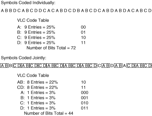
An input stream with a more highly skewed probability distribution can take advantage of a VLC table that results in a VLC output stream with a lower number of average bits per pixel. However, it is possible to modify the input stream to further skew the probability distribution before VLC coding. The encoder performs this modification by coding input symbols jointly. Two or more symbols are coded jointly if they have a higher probability of appearing together, rather than separately. As an example, Figure 3-13 shows an input symbol string with four symbols: A, B, C, and D.
When considering each symbol individually, the probability distribution is flat, meaning that each symbol on average appears 25 percent of the time. The VLC code table for this distribution would contain codes of the same length, which means that simple VLC coding of these four symbols would not reduce the number of bits per value. However, in this symbol stream, the A symbol is often followed by the B symbol, and the C symbol is often followed by the D symbol. In this case, an improved VLC code table would code the A and B symbols jointly and the C and D symbols jointly by adding two new entries to the VLC code table. When an A symbol is followed by a B symbol in the data stream, this pair is coded with a single variable-length code, and similarly for a C symbol followed by a D symbol. The new input symbol set has a highly skewed probability distribution and can benefit from a VLC.
H.26x codecs achieve a VLC coding with a lower average number of bits per pixel by first applying run-length coding of the AC coefficients and then coding the run and length values jointly. Statistically, certain combinations of run and length occur together with high frequency, further skewing the probability distribution and thus improving the performance of VLC coding.
The VLC decoder uses the code table to perform the mapping operation in reverse. At each stage of the VLC decoding process, the decoder finds the VLC code in the code table that matches the bits that appear next in the bitstream from the encoder.
One of the disadvantages of VLC is that it usually cannot achieve an average number of bits/pixel that is as low as the theoretical entropy of a bitstream.
As you can see in Figure 3-13, with symbols coded individually, the theoretical entropy is 2 bits per pixel, and the VLC table achieves this average number of bits per symbol. When the same stream is coded jointly, the theoretical entropy is 1.92 bits per symbol, but the VLC table achieves an average bit rate of 2.2 bits per symbol. The reason the VLC cannot achieve the theoretical entropy is because the bit length of each symbol is restricted to an integer number of bits per symbol. In general, VLC coding generates an output bitstream with an average number of bits per symbol that is often 5 percent to 10 percent greater than the theoretical entropy. One way to effectively achieve a fractional number of bits per symbol is to use arithmetic coding rather than VLC coding.
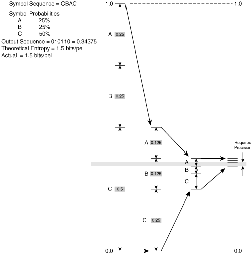
Given an input symbol set, arithmetic coding is an entropy coding mechanism capable of achieving an average number of bits per pixel equal to the entropy of the bitstream by effectively coding each symbol using a noninteger number of bits per pixel. The idea of entropy coding is to convert the entire sequence of input symbols into a single floating-point number. This number is constrained to have a value within a preset range. One sample range is the span between 0.0 and 1.0. The only requirement for this floating-point number is that it must have enough digits of precision to represent the symbol sequence; the longer the symbol sequence, the more digits of precision that are required.
The arithmetic coder follows a series of steps to derive the value of this floating-point number. To set up the encoding process, the encoder establishes a working range by setting the upper level of the range to 1.0 and the lower level of the range to 0.0. As the encoder processes the symbols, it uses an algorithm that causes the upper level to reduce over time and the lower level to increase over time. As a result, the working range narrows after each symbol is coded. After all the symbols have been coded, the encoder calculates a floating-point number with enough precision to fall within the final working range. This floating-point number represents the entire coded bitstream. Figure 3-14 shows the steps needed to determine the final working range.
Figure 3-14 illustrates the method used to code the input stream, which in this example consists of three unique symbols. The process involves three main steps:
Divide the working range into spans, as shown in Figure 3-14. Given N possible unique symbols in the bitstream, there will be N spans in the working range, and each span has a distance proportional to the symbol probability. This type of arithmetic coder is often referred to as an N-arry arithmetic coder because there are N spans, corresponding to N unique symbols in the input stream. If a symbol has a probability of .1, its corresponding range will be equal to 10 percent of the working range. In this example, the input symbols A, B, and C each have probabilities .25, .25, and .5. It does not matter in what order the spans appear within the working range.
The encoder reads a symbol from the input stream and finds the corresponding span in the working range. This span becomes the new working range and defines the new upper level and lower level of the range.
Return to Step 1 and repeat, using the new smaller working range, subdivided into spans.
When the final working range is determined, the encoder must calculate a binary floating-point number with enough precision to place the number entirely within the working range. In Figure 3-14, this final binary number is .010110, equal to a decimal value of 0.34375. The final binary number is selected such that it will still fall within the working range after it is extended by an infinite number of 1s. In other words, if the binary number .010110 were extended to .010110111111111 ..., this extended number would still fall within the working range.
The decoder derives the original symbol stream from the floating-point number using steps similar to the encoding process. The decoder starts with the same initial working range of 0.0 to 1.0 and then determines the span in which the floating-point number falls to decode the first symbol. The decoder then iteratively narrows the working range and repeats the process.
In practice, an arithmetic coder can create an output stream with an average number of bits per symbol equal to the theoretical entropy of the input stream. As a result, arithmetic coding generates an encoded stream with a bit rate that is typically 5 percent to 10 percent less than a VLC encoded bitstream.
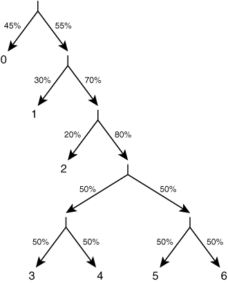
The arithmetic coder described in the preceding section, with N spans, is called an N-arry arithmetic coder. Another type of entropy coder is the binary arithmetic coder. In this case, there are only two spans in the working range, representing a binary decision. Each symbol is encoded as a sequence of binary decisions, where each decision narrows the working range. Figure 3-15 shows an example of a binary decision tree used to code symbols using a binary arithmetic coder.
The first decision is whether the symbol is 0 or not 0. For this decision, the spans in the arithmetic coder are sized to reflect the probabilities for this decision. After this decision, the second stage of the decision tree determines whether the symbol is 1 or not 1. For this second decision, the encoder uses a different set of spans, which reflect the probabilities for this decision point. At each binary decision point, the encoder swaps in a new set of spans optimized for the probabilities for that decision point. Of course, the decoder must also use the same set of spans at the same decision points to remain in lockstep with the encoder.
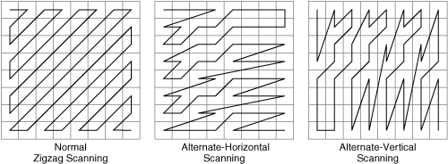
Entropy coding operates on one-dimensional data only, which means that the encoder-side processor must convert the two-dimensional array of quantized DCT coefficients into a one-dimensional array. This conversion process uses one of several DCT scanning patterns. Figure 3-16 shows some sample patterns for the 8×8 DCT.
The purpose of the DCT scanning pattern is to create a one-dimensional array that maximizes the efficiency of the entropy coder. Maximum efficiency is generally obtained by scanning the largest magnitude coefficient values first and the smallest magnitude coefficient values last. This distribution provides two benefits:
It skews the probability distribution of possible values for each coefficient, which lowers the theoretical entropy, resulting in fewer bits per value.
It allows the entropy coder to better estimate the actual probability distribution of possible values for each coefficient, which allows the encoder to optimize the method of entropy coding.
Encoders can specify different scanning patterns to optimize the performance of the entropy coder. The encoder can signal the best scanning pattern either explicitly, or implicitly as a function of previously decoded pixels. The selection of the scanning pattern depends on the frequency content in that block:
An 8×8 block with no bias toward horizontal or vertical frequencies should use normal zigzag scanning, because most of the nonzero coefficients will be biased in the upper left quadrant of the DCT.
An 8×8 block with somewhat greater horizontal frequency content (for instance, many vertical lines) should use alternate-horizontal scanning, because most of the nonzero coefficients will be biased in the top half of the DCT.
An 8×8 block with somewhat greater vertical frequency content (for instance, many horizontal lines) should use alternate-vertical scanning, because most of the nonzero coefficients will be biased in the left half of the DCT.
Most of the stages in a codec can make use of adaptive coding. Adaptive coding optimizes the performance of a codec by varying the codec algorithm parameters during the encoding process. One common example is adaptive VLC coding, which switches among different VLC symbol code tables from moment to moment in response to changes in the probability distribution of the input data stream. However, with any adaptive scheme, the decoder must be able to figure out how the parameters have changed to remain in lockstep with the encoder. The encoder uses one of two methods to communicate the parameters in use:
Explicitly signaling the algorithm parameters in the bitstream. The encoder can inject side information into the bitstream to communicate the most suitable set of parameters to use for an encoding process. The downside of this process is that the side information increases the bit rate of the encoded stream. As an example, codecs explicitly transmit the value of the DCT quantization step size.
Implicit parameter selection based on past decoded information. This process is often referred to as content-adaptive processing. In this scenario, information that has already been decoded by the decoder (and also observed by the encoder) is used to determine future codec parameters. Both the encoder and decoder must use the same information and the same content-based analysis to calculate the codec algorithm parameters.
The benefit of this method is that no additional side information needs to be transmitted to signal the parameter selection. The downside is that this previously decoded information might not correctly predict the best set of codec parameters to use. One example of content-adaptive coding is from H.263, MPEG-4 Part 2, and H.264. All three codecs have a mode to determine the zigzag DCT scanning pattern for a block, based on whether the block is expected to be dominated by strong vertical or horizontal frequencies. This determination is made by observing the frequency content of previously decoded neighboring blocks.
One type of content-adaptive processing is a content-adaptive VLC processor. In this case, the VLC table changes over time in response to the statistical properties of recently decoded information. One example is the content-adaptive VLC (CAVLC) in H.264, which defines several VLC tables for coding the quantized DCT coefficients.
The selected table is a function of parameters from two previously decoded blocks: the block located to the left of the current block, and the block located above the current block. The content-adaptive algorithm uses several parameters from those blocks, including the number of nonzero DCT coefficients, the type of MB (P, B, and so on), and whether the block used a special intra prediction mode. The decoder mirrors these adaptive algorithms and selects the same VLC table as the encoder on a block-by-block basis to stay in lockstep with the encoder.
Whereas a content-adaptive VLC coder chooses from among several pre-fixed VLC tables, a content-adaptive arithmetic coder incrementally modifies its own span lengths as a function of the statistics of recently decoded information. The goal is to change the span lengths so that they are proportional to the probabilities of the symbols in the input stream. In the case of a binary arithmetic coder, the adaptive coder attempts to make the span lengths proportional to the estimated probabilities of each binary decision.
A common feature of adaptive arithmetic coders is a state machine that attempts to “learn” about the statistical distribution of input symbols over time to make the best guess for the span lengths. Much like the adaptive VLC, both the encoder and the decoder must use the exact same algorithm to determine span lengths so that they both remain in lockstep. One example is the content-adaptive binary arithmetic coder (CABAC) in the H.264 codec.
The previous discussion covered the coding steps taken for intraframes. As discussed in the section “Encoder and Decoder Overview,” intraframes are coded using information only from the current frame, and not from other frames in the video sequence. However, other than Motion-JPEG, codecs for video conferencing use a hybrid approach consisting of spatial coding techniques discussed previously, along with temporal compression that takes advantage of frame-to-frame correlation in the time domain. The encoder describes this interframe correlation using motion vectors, which provide an approximation of how objects move from one frame to another.
The next sections discuss the interframe coding process, which uses a feedback loop along with motion estimation to take advantage of frame-to-frame correlation.
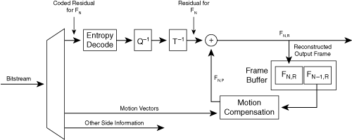
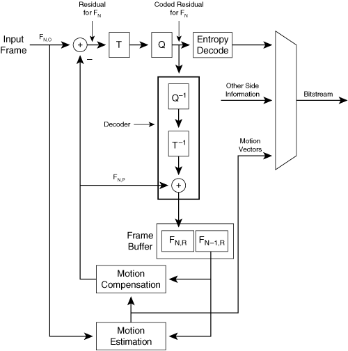
When analyzing a hybrid codec, it is easier to start by analyzing the decoder rather than the encoder, because the encoder has a decoder embedded within it. Figure 3-17 shows the block diagram for the hybrid decoder.
The encoder creates a bitstream for the decoder by starting with an original image, with frame number N, denoted by FN,O. Because this frame is the original input to the encoder, it is not shown in the decoder diagram of Figure 3-17. For this image, the output of the encoder consists of two chunks of information in the bitstream: motion vectors and coded image information. The encoder forwards this information to the decoder; it is the input on the left side of Figure 3-17.
The motion vectors describe how the decoder should manipulate the previously decoded image to become an approximation of the current original image FN,O. The previously decoded image is referred to as the reference frame, denoted by FN–1,R, and the approximation for the current frame FN,O is called the predicted frame, denoted as FN,P.
To create the motion vectors, the encoder divides the original image N into blocks of size 4×4, 8×8, or 16×16 (depending on the codec) and then calculates a motion vector for each block. The motion vector points to a pixel area in the previously decoded reference image FN–1,R that most closely resembles the block in the original image FN,O.
On the receiver side, the decoder creates FN,P by starting with a blank image and then dividing it into an array of blocks, just like in the encoder. For each block in FN,P, the decoder uses the motion vector for that block to extract the corresponding area from the previously decoded reference frame FN–1,R. This process is called motion compensation.
However, this predicted frame FN,P is usually a crude approximation of the original frame FN,O, because motion vectors can describe only simple translational motion of blocks of pixels. Motion vectors cannot describe nonuniform movement of objects in the image or handle cases where overlapping objects move in such a way as to reveal or obscure each other. To enhance this crude predicted frame FN,P, the encoder also creates the same FN,P and then sends the difference between the predicted frame FN,P and the original frame FN,O. This difference is called the residual. The encoder then performs spatial coding on this residual, using the usual sequence of DCT/quantization/entropy coding, to create the coded residual. The final bitstream created by the encoder consists of the coded residual multiplexed with the motion vectors.
The decoder decodes the coded residual for frame FN and then adds it to the predicted frame FN,P to create the fully decoded image. The resulting decoded frame is called the reconstructed image. The two image buffers in the frame buffer hold both the currently decoded image FN,R and the previously reconstructed image FN–1,R. After the decoder finishes creating FN,R, this frame is then used as the reference frame for the next image, FN+1.
Note one important thing about this spatiotemporal coding process: The encoder and decoder must create the exact same predicted frame FN,P to remain in lockstep. The decoder creates the predicted frame by manipulating the previous decoded frame FN–1,R, which is reconstructed after a lossy encode/decode process. Because FN–1,R is the result of a lossy reconstruction, the encoder must also use the same lossy decoding reconstruction process to derive the same FN–1,R. Therefore, the encoder must have a decoder within it to reconstruct the same decoded frame that is reconstructed at the decoder. The encoder then applies the motion vectors to FN–1,R, in the same manner as the decoder to derive the predicted frame FN–P If the codec specifies a deblocking filter, the motion compensation is applied after the deblocking filter. As a result, the deblocking filter is inside the feedback loop. When used in this manner, the deblocking filter can reduce the bit rate of the stream slightly, in addition to lowering the perceptual degradation of block artifacts.
An interframe predicted using motion vectors that point to a previous frame is referred to as a P-frame, short for predicted frame. However, for some video codecs, a P-frame is not restricted to using the most recent frame in the video sequence. The P-frame may instead refer to one of several frames that have appeared in the recent past. For example, the H.264 codec may include motion vectors that refer to one of several previous frames, and the motion vector must also include an index to designate which frame is used.
Even if a frame is considered a P-frame, it may contain MBs that are intracoded. If the video contains a lot of motion, the motion compensation for that block might not result in pixels that resemble the corresponding pixels in the original image. In this case, the encoder may decide to code a block or MB as an intrablock by applying the transform/quantize/entropy coding pipeline directly to original image pixels.
Figure 3-18 shows the data flow of the corresponding hybrid encoder.
When encoding frame FN,O, the first step is performed by the motion estimation unit, which calculates the motion vectors that transform the previously reconstructed image FN–1,R into the current predicted image FN,P. However, the motion estimation unit does not directly create the predicted image FN,P. Instead, the motion estimation unit sends these motion vectors to the motion compensation unit, which applies the motion vectors to previously decoded frame FN–1,R to create the predicted frame FN,P. The motion compensation units in the encoder and decoder are identical. The encoder subtracts the predicted frame FN,P from the original frame FN,O, generating residual image data. If the images have a precision of 8 bits per pixel, each pixel, in both the original frame and the reconstructed frame, can range from 0 to 255. As a result, the residual values at the output of the subtraction unit have a possible range of [–255, 255]. The encoder applies the DCT transform to this residual image, followed by quantization and entropy coding, to create a coded residual.
To complete the loop, the encoder must perform the same steps as the decoder by decoding image N to create FN,R, which is used to create the prediction FN+1,P for the next encoded frame. To perform this reconstruction, the encoder contains a decoder, as shown in Figure 3-18. This embedded decoder performs inverse quantization and IDCT on the coded residual and then adds the resulting decoded residual to the predicted frame FN,P to obtain the reconstructed image FN,R.
However, the embedded decoder needs to perform only the lossy steps of the decoder process, which includes inverse quantization and IDCT. Because the entropy coding is lossless, the embedded decoder can begin with data that emerges from the output of the quantizer and still obtain the same reconstructed image FN,R as in the decoder. Note that any processing block that is inside the encoder loop must be duplicated exactly in the decoder loop so that both encoder and decoder remain in lockstep.
The operation of the decoder is not affected by operations that happen outside of the encoder loop, and therefore these operations are considered outside the scope of the codec standards. The most significant example of a processing step outside the encoder loop is the motion estimator. The method by which the encoder performs motion estimation is not specified in any of the codec standards; the standards leave the method of motion vector selection up to the encoder.
The example in Figure 3-18 made the assumption that all blocks in the interframe are intercoded with motion vectors. However, video codecs typically define interframes to consist of both intercoded blocks and intracoded blocks. The encoder makes this determination on an MB basis, which means that the encoder must also send this per-MB decision as side information inside the bitstream. For each block, the encoder finds the motion vector that provides the best match between adjacent frames; if this best motion vector results in a large residual, however, the encoder may instead code the block as an intrablock, which means the encoder and decoder will not use the feedback loop for that block. When encoding an intrablock, the encoder applies the DCT to original image pixels, which have a range of [0, 255], rather than to the residual values, which have a range of [–255, 255].
The prediction-based hybrid codec relies on the fact that the encoder and decoder use the exact same predicted frame. Because the predicted frame is generated from the reconstructed frame, the reconstructed frame FN,R in the encoder should be identical to the reconstructed frame FN,R in the decoder. If the two reconstructed frames deviate, the deviations accumulate with each pass of the feedback loop, and the encoder and decoder drift away from each other over time.
To ensure that the reconstructed frames in the encoder and decoder are the same, the lossy decoding process in the encoder (inverse quantization followed by IDCT) should ideally be mathematically identical to the same process in the decoder. The inverse quantization step is a simple, well-defined process that uses integer math; therefore, this step is naturally identical in the encoder and decoder. However, the same is not always true for the inverse 8×8 DCT. Even when using 32-bit floating-point math, different implementations of the IDCT may result in pixel residuals (for an interblock) that have slight deviations. Codec specifications take these deviations into account in two ways:
Codecs typically specify the maximum deviation tolerance for the IDCT. Each pixel output of the IDCT is typically allowed to deviate from the exact theoretical output by no more than a single brightness level out of 255. In addition, codec specifications often limit the sum total deviation of all pixels in the 8×8 block.
To prevent these small deviations from accumulating over time, the H.261 and H.263 codecs recommend that each block should be transmitted as an intrablock, with no dependency on the predictor loop, on average once every 132 times the block is coded. This suggestion is referred to as an informative recommendation because it is a suggested best practice and is therefore technically outside the scope of the codec standard.
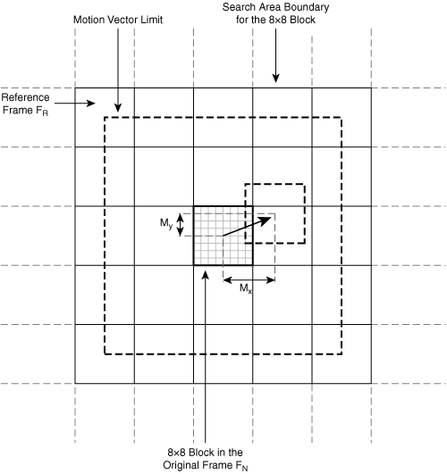
Figure 3-19 shows the motion estimation process on the encoder, which is by far the most CPU-intensive step in the encoder/decoder system.
For each block in the original image FN, the encoder searches the reference frame FR in the same vicinity to find a reference block most highly correlated to the original. In this example, the block size is 8×8, and the encoder limits the motion vector to a range of ±16 pixels for both X and Y components.
For each block in the original image, the encoder compares candidate motion vectors within the possible motion vector range. For each possible motion vector, the encoder determines the level of correlation between the original block and the candidate reference block by calculating the error between the two blocks. Encoders use different measurements to calculate the error, but a common formula is the sum of absolute differences. In this formula, the encoder computes the absolute difference between corresponding pixels and then adds the results to create the error:
For the encoder to determine the error for a single candidate motion vector using this formula on 8×8 blocks, the encoder must perform 64 subtraction operations followed by 64 additions. In this example, where motion vectors can have integer values in the range [–16, +15], there are a total of 32×32 = 1024 possible candidate motion vectors, including the (0,0) motion vector. For the encoder to find the best motion vector, it must calculate the correlation error for all 1024 candidate motion vectors and then use the one with the minimum error value. This process requires (64+64)×1024 = 131,072 calculations per 8×8 block in the original image. For a CIF video sequence with a format of 352×288 / 15 FPS, the number of calculations for motion estimation alone using this technique will be 131,072 calculations × 1584 blocks per frame × 15 frames per second = 3.1 billion calculations per second.
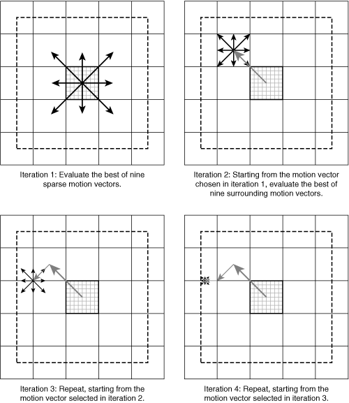
To reduce the computational load of the motion estimation process, the encoder may test only a subset of candidate motion vectors per block. In addition, the encoder can adopt an iterative approach, as shown in Figure 3-20.
The encoder first tests a sparse set of motion vectors within the search range and uses the vector with the lowest error to narrow the search area for the following iteration. The encoder repeats this process until the last iteration, when the encoder compares candidate motion vectors that point to one of nine offsets in a 3×3 pixel area.
However, special-purpose signal processors can provide an exhaustive motion search for each block in the original image without resorting to this iterative technique. High-end, standalone, room-based systems usually have these special processors; this difference accounts for the higher quality and lower bit rates of room-based video conferencing endpoints compared to PC-based desktop endpoints. The need for high-computation motion estimation in the encoder is also the reason that some PC-based endpoints use dedicated external hardware for the encoding process but use PC-based software for the decoding process.
One important thing to understand about motion vectors is that they point in the opposite direction of the data transfer. In Figure 3-19, the motion vectors chosen by the motion estimation unit point from the current original image FN to the previous reconstructed image. However, in actuality, the motion compensation unit forms the predicted image by moving data in the opposite direction, from the tip of the arrowhead (in previous reference frame FN–1,R) back to the tail (in the current predicted frame FN,P). Therefore, a motion vector points to the source rather than to the destination.
The motion estimation process is applied only to the luminance channel: These luminance vectors are divided by a factor of 2 to obtain the motion vectors used for the chrominance channels, which have half the resolution in the 4:2:0 color format.
Different codecs use different variations of motion estimation. Higher-performance codecs allow motion vectors with more precision, down to 1/4 pixel. To further improve the accuracy of a reconstructed image, some codecs offer an advanced mode that varies the actual motion vector over the span of an 8×8 block, described later in section “Overlapped Block Motion Compensation.” In addition, codecs can specify that a frame should be motion- compensated based on multiple motion vectors, each pointing to a separate reference frame.
In the motion estimation unit, pixels in the reference frame are considered to be color values located at integer X and Y locations. Motion vectors with single-pixel accuracy will map integer-aligned pixels in the reference frame to integer-aligned pixel locations in the original image frame.
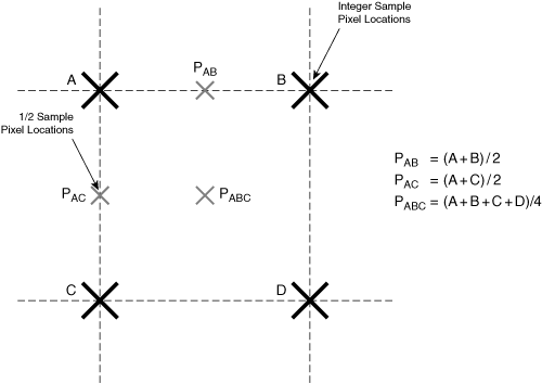
However, some codecs allow motion vectors to have an accuracy of 1/2 pixel or 1/4 pixel (also known as 1/2 pel or 1/4 pel), described later in the section “Overlapped Block Motion Compensation”. In these cases, each motion vector can point to a source location in the reference frame that represents an array of pixels offset by a fractional pixel distance from the integer-located reference pixels. The decoder must interpolate these in-between pixel values. Figure 3-21 shows the method of interpolating 1/2 pel locations based on a simple two-dimensional bilinear filter.
However, 1/4 pel interpolation used in H.264 typically requires an interpolation filter with higher accuracy to effectively make use of the finer 1/4 resolution.
When the motion estimator searches for a motion vector with 1/2 or 1/4 pel accuracy, the encoder first chooses the best motion vector down to single-pel accuracy and then proceeds to find the best 1/2 or 1/4 pel accurate motion vector in close proximity to that integer-pel vector. To find the best 1/2 pel motion vector, the encoder first scales up the candidate area of the reference frame by a factor of 2 in the X and Y direction using the interpolation filter. The encoder then calculates the correlation error for the eight possible surrounding 1/2 pel (x,y) motion vector offsets and chooses the motion vector that results in the lowest error.
Video codecs define the maximum range of motion vectors. The basic modes of operation for the codecs covered in this chapter use a range of approximately +/– 15 pixels for X and Y motion vector components, but some codecs offer modes that permit the X and Y components to be more than double this basic range.
Another convention of video codecs has to do with restricted and unrestricted motion vectors. A restricted motion vector is a motion vector that must only refer to pixels entirely within the boundaries of the reference frame. However, some codecs have optional modes that allow unrestricted motion vectors, which can refer to regions outside the picture boundaries. For these outer regions, the encoder and decoder fill in the missing pixels by creating a pixel value using the closest edge pixel in the frame.
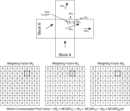
One advanced motion compensation technique is overlapped block motion compensation (OBMC), illustrated in Figure 3-22.
OBMC allows the motion vector to vary on a per-pixel basis over the span of the block. Each pixel is motion-compensated using motion vectors from the current block and motion vectors from surrounding blocks. The possible surrounding blocks that may provide the additional motion vectors are the four blocks that are horizontally or vertically adjacent, as shown in Figure 3-22. The compensation unit uses motion vectors from two of these four blocks, determined on a per-pixel basis, according to the position of the pixel in the current block: For each pixel, the motion compensator uses the closest horizontally adjacent block and the closest vertically adjacent block. Therefore, the motion compensator uses a different set of motion vectors for pixels in each quadrant of the current block.
In Figure 3-22, the candidate pixel is closest to the top and right sides of the current block, so the compensator uses motion vectors from the adjacent blocks directly above and to the right of the current block. Based on each motion vector, the decoder first calculates three motion-compensated pixel values. Then the motion-compensation algorithm applies a weighting value to each motion-compensated predicted pixel. The weighting value for each motion vector is a function of the pixel location in the current block and is given by weighting matrices. Figure 3-22 shows the matrices for MPEG-4 Part 2. The weighted prediction values are summed to calculate the final predicted pixel value.
For some codecs, interframes are not restricted to contain only P-frames. Another type of interframe is the B-frame, which uses two frames for prediction. The B-frame references a frame that occurs in the past and a frame that occurs in the future. The term B-frame is short for between-frame.
Figure 3-23 shows a sequence of I-, P-, and B-frames.
The arrows in Figure 3-23 show the dependencies between frames. The dependency of a frame can be determined by observing the arrows that point to the frame. The source of each arrow represents a dependency. Each P-frame depends on a previous P- or I-frame. Each B-frame depends on the nearest surrounding I- or P-frame.
When encoding a B-frame, the encoder sends two motion vectors for each block. The motion vector that points to a previous reference frame is called the forward motion vector because this motion vector extrapolates motion forward in time. The motion vector that points to a future reference frame is called the backward motion vector because this motion vector extrapolates motion backward in time.
The encoder and decoder predict each block in a B-frame by extracting the pixel areas referenced by the two motion vectors and then averaging those pixel areas to create the block for the predicted frame FN,P. Even though B-frames require additional side information in the bitstream for the extra motion vectors, compressed B-frames are often much smaller than I- or P-frames.
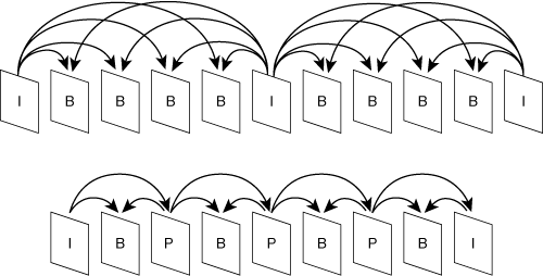
The encoding/decoding of a B-frame is a noncausal process, because the B-frame cannot be processed until after a future frame is processed. To make the decoding process easier, the encoder reorders frames in the encoded bitstream so that the backward-referenced frame appears before the B-frame, as shown in Figure 3-24.
Any frame dependencies required by a B-frame appear in the bitstream before the B-frame. The resulting sequence of frames is called the bitstream order, transmission order, or decoding order. After decoding, the decoder must reorder the frames to match the original video sequence, and this final order is called the display order, temporal order, or picture number order.
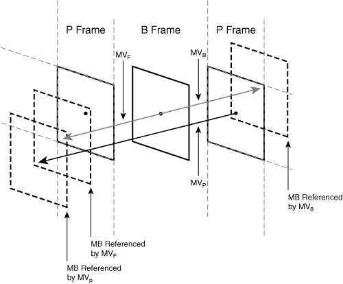
One additional B-frame mode is called direct mode. In this mode, the encoder does not include the usual forward and backward motion vectors with the B-frame. Instead, the B-frame derives its forward and backward motion vectors from the motion vector used by the corresponding block of image data in the next frame.
Figure 3-25 shows the derivation. When a frame is coded with this mode, the corresponding block of data in the next frame must have a motion vector associated with it, even though it may be an intrablock. Therefore, the B-frame direct mode is one example in which an intrablock must still have a motion vector.
If objects travel at a constant rate, in a straight line, from the previous reference frame to the next P-frame, the decoder can simply use bilinear interpolation to estimate the motion vectors that apply to the B-frame. However, if the motion deviates from a straight line, or deviates from a constant speed during this time span, the encoder may also send a small delta vector that compensates for this deviation. The decoder adds the delta vector to each interpolated motion vector to arrive at the final motion vectors. Most video conferencing codecs that support B-frames have a direct mode, but not all of them include a delta vector correction.
Figure 3-26 shows other possible I-, P-, and B-frame patterns. Patterns of I-, P-, and B-frames are often referred to as IPB patterns. Specific patterns are often expressed using a notation that strings together single letter frame types. The first example in Figure 3-26 has an IPB pattern of IBBBB. The second example has an IPB pattern of IBPBPBPB.
In all sequences, P-frames depend on I-frames or other P-frames, and B-frames depend on P- or I-frames. A disadvantage of using P-frames is that if an I-frame or P-frame is corrupted due to channel errors or packet loss, the error propagates through the frame sequence until the sequence reaches an I-frame.
There is one universal requirement for sequences of I-, P-, and B-frames: No frame may depend on a B-frame as a reference. As a result, a corrupted or lost B-frame will not cause an error to ripple through the sequence. Viewed from another perspective, either the encoder or decoder may discard B-frames to reduce the frame rate, without causing errors in other frames. For example, the encoder may discard B-frames to keep the bitstream from exceeding a predetermined maximum channel bit rate.
Alternatively, the decoder can drop B-frames if it has insufficient CPU power to provide the full frame rate. The capability to gracefully scale down the frame rate in this manner is called temporal scalability. An equivalent way of describing this scalability is to say that B-frames are not retained inside the predictor loop of the encoder and are therefore not needed to predict other frames. Because B-frames are not in the feedback loop, post-processing of those B-frames using a deblocking filter is technically out of scope in the codec specifications, even though the deblocking filter is in scope for I- and P-frames.
B-frames pose a significant problem for video conferencing because they add latency to the video bitstream. A sequence consisting of IBBPBBPBBPBBI requires the encoder to add a delay of two frames to its pipeline, because the encoding of the B-frames must be delayed until the next P or I frame is encoded. Typically, this video delay adds an unacceptable latency to the one-way path between two video conferencing endpoints.
The section “Predictor Loop” explained the predictor loop for a hybrid codec, in which the output of the encoder is a coded residual image based on a motion-compensated predicted frame. This prediction loop forms the outer loop of a hybrid coder. However, this paradigm of coding a residual can be extended to other parts of the codec algorithm and is not limited to motion-compensated prediction of pixel areas. Most codecs use smaller prediction loops in various parts of the bitstream. Like the hybrid coder prediction loop, the encoder and decoder may form a prediction based on information accessible to the decoder. Therefore, the prediction can be based on the following:
Information in previously decoded frames.
Information in the current frame that has already been decoded. Because the encoder usually processes MBs in raster-scan order, the previously decoded image information consists of image data to the left of or above the current MB.
However, unlike the outer loop of a hybrid coder, some of these inner loops use only lossless entropy coding to code the residual.
The most common predictor loop specified by video codecs is the coding of motion vectors for a block. In this case, the codec creates a predictor by extracting the motion vectors of surrounding previously decoded blocks in the same frame and then takes the average value of these motion vectors as the predictor for the current MB. The encoder then creates a residual by subtracting the prediction from the actual value of the motion vector. The encoder then codes this residual losslessly. Similar to the outer loop of the hybrid coder, both the encoder and decoder must use the same algorithm to calculate an identical predictor. For motion vectors, this predictor often uses an average of three motion vectors, relative to the current block or MB:
The motion vector from the block to the left of the current block
The motion vector from the block above the current block
The motion vector from the block to the left of and above the current block
However, in a case like this that uses multiple input values, the predictor algorithm may specify either an average of the values or a median of the values. The median is defined as the middle value. The advantage of using a median value is that it tends to reject outward-lying values, which may result from either noise or anomalous corner case conditions.
However, encoders use variations on these prediction algorithms when surrounding information is not available, which may happen in several scenarios:
8×8 blocks located at the left edge of the frame do not have a neighboring block to the left.
8×8 blocks located at the top edge of the frame do not have a neighboring block above.
Information in neighboring blocks might not be available. For instance, a neighboring intrablock has no motion vectors; therefore, the prediction algorithm cannot make use of motion vectors from this neighboring block.
In these cases, encoders specify variations of the prediction algorithm to handle these cases. For example, if a neighboring block is either nonexistent or without a motion vector, a prediction algorithm may instead use a motion vector prediction of zero.
As an example of another predictor loop, some codecs predict DCT coefficients for blocks that are intracoded. This process is applied after the DCT, and the DC coefficient is often treated differently from the AC coefficients. Because the DC coefficient represents the block’s average value, it is often predicted by averaging the DC coefficients of three adjacent blocks: the block to the left, the block above, and the block to the above left.
Some AC coefficients can also be predicted, but only if the encoder and decoder can detect that the block will have strong vertical frequencies or strong horizontal frequencies. The prediction algorithm can determine whether the block is likely to have strong horizontal or vertical frequencies by observing the frequency content of adjacent blocks, resulting in two scenarios:
If the block to the left has strong vertical frequencies, corresponding to strong horizontal edges, these edges are likely to continue into the current block that is being decoded. These strong horizontal edges are represented by large values for AC coefficients in the first column of the current DCT, and these values are likely to be the same as corresponding DCT values in the block to the left. Therefore, in this scenario, the prediction for the first column of AC coefficients will be the corresponding column of AC coefficients in the block to the left. The remainder of the AC coefficients are coded separately.
If the block above has strong horizontal frequencies, corresponding to strong vertical edges, these edges are likely to continue into the current block that is being decoded. These strong vertical edges are represented by large values for AC coefficients in the first row of the current DCT, and these values are likely to be the same as corresponding DCT values in the block above. Therefore, in this scenario, the prediction for the first row of AC coefficients will be the corresponding row of AC coefficients in the block above. The remainder of the AC coefficients are coded separately.
After using this prediction, the residual is entropy-coded.
H.264 has a mode that predicts an intrablock in the spatial domain (before DCT coding) by observing motion vectors from neighboring blocks. Based on these motion vectors and the spatial pixel content of these neighboring blocks, the H.264 algorithm attempts to predict how pixel values from surrounding blocks have entered the current block. After using this prediction, the residual is DCT coded like a typical interblock.
The predictor algorithm can also define circumstances in which a prediction should not be used, in cases where previously decoded data indicates that no good predictor is available. For this case, the predictor specifies a nominal prediction value, such as zero; a zero predictor value is the same as using no prediction. However, nominal prediction values may be nonzero. For example, when an intrablock is coded without using predictions from surrounding blocks, the predictor for the DC coefficient of the intrablock typically uses a value that is the midpoint of its possible range. That is because the DC coefficient represents the average value of all pixels in the original block, and a predictor value equal to the halfway point minimizes the average residual error.
If the network drops bitstream packets, decoders may have difficulty resuming the decoding process for several reasons:
Bitstream parameters may change incrementally from one MB to another. One example is the quantization level: Most codecs allow the bitstream to change the quantization level by a delta amount between MBs. If the network drops a packet, the decoder will not have access to the previous incremental changes in the quantization level and will not be able to determine the current quantization level.
Bitstream prediction loops may depend on other previously decoded parts of the bitstream. If a packet drops, data in this packet cannot be used as part of the prediction loop in the future.
Video codecs provide error resiliency using several methods:
Explicit error correction, such as forward error correction (FEC)
Unique start codes
Reversible VLCs
Data dependency isolation
Redundant slices
Data prioritization
The following sections describe each.
Forward error correction (FEC) is a process that uses extra bits to detect and correct for errors in the bitstream. When using FEC, the bitstream is first segmented into packets, and then the FEC process is applied to each packet.
Start codes in the bitstream demarcate boundaries between major segments of the bitstream. Each type of start code is assigned a pattern that must not be used by any other bitstream syntax element. If a decoder encounters an error in the bitstream and is unable to determine the alignment of coded parameters, the decoder scans the bitstream until it finds the next start code, and then it resumes parsing the bitstream. In this approach, the decoder cannot use the bitstream between the location of the bit error and the next start code unless the bitstream uses a reversible VLC, discussed next.
Reversible VLCs permit a decoder to parse a bitstream by scanning the bitstream in either a forward or reverse direction. To make use of a reversible VLC, the decoder first decodes the bitstream in the forward direction. If the decoder encounters an error, it scans forward in the bitstream until it finds the next start code, and then the decoder scans backward from the start code and parses the bitstream in reverse, using reversible VLC codes, until it again encounters the bitstream error. Therefore, a reversible VLC allows the decoder to parse as much of the uncorrupted bitstream as possible in the presence of an error.
Table 3-5 shows an example of a reversible VLC table. The value of s codes the sign of the number. In a normal VLC table, no VLC entry is permitted to be a prefix of any other entry. A reversible VLC adds one additional requirement: For the purposes of backward scanning, no VLC entry is permitted to be a suffix of any other entry.
However, a reversible VLC table will not provide error resiliency for packets discarded by the network because of bit errors.
Data dependency isolation attempts to minimize the dependencies between segments of the bitstream. Typically, a codec defines a bitstream hierarchy. At the top of the hierarchy is a frame of video. This video frame consists of groups of blocks (GOB) or slices. Each GOB/slice consists of a series of MBs, each of which represents a 16 × 16 pixel array.
Senders usually packetize video bitstream so that each RTP packet contains bitstream from a single GOB/slice. As a result, if an RTP packet is lost on the network, the data loss is confined to a single GOB/slice. To provide error resilience in the presence of packet drop, each GOB/slice should not depend on any other GOB/slice in the frame. This requirement means that all predictor loops in the codec should restrict their prediction algorithms to use information that is within the current GOB/slice only. Motion vectors are often predicted as a function of the motion vectors in surrounding MBs. To provide data dependency isolation, this prediction method should use motion vectors only from blocks in the same GOB/slice. Many codecs offer a mode to provide this data dependency isolation between GOBs/slices.
Codecs may send redundant slices, which often have a smaller size and lower quality. The decoder may use these redundant slices in place of corrupted slices.
Codecs may provide ways to classify the bitstream by levels of importance and then apply a different quality of service to the different levels:
At the MB level, the encoder can classify some MBs in the image to be more important: These MBs generally contain movement and must be decoded correctly to provide good quality at the decoder. One way to provide a higher level of quality for these MBs is to arrange them into one or more slices and then send these slices over the network with a higher quality of service. In H.264, flexible MB ordering (FMO) allows each slice to contain an arbitrary collection of MBs in a frame, allowing the encoder to collect the most important MBs into a single slice.
Encoders typically use Arbitrary Slice Ordering (ASO) with FMO. ASO allows slices to be sent in an arbitrary order.
The encoder may use slice classification. In this mode, the encoder defines different slice classifications. Slice-based classifications include header information, non-B-frame information, and B-frame information. The encoder may send each type of slice with a different quality of service.
The encoder may use data partitioning. Data partitioning reorganizes the data in each slice of the bitstream so that common values are grouped. This approach uses a reversible VLC, and the final arrangement allows better error recovery. H.263 defines the following data partitioning per slice:
First, the encoder sends the MB headers.
Then, the encoder sends all motion vectors, in the form of coded differences.
Then, the encoder sends DCT coefficients.
Scalable codecs offer a way to achieve progressive refinement for a video bitstream. A scalable bitstream is composed of a base layer accompanied by one or more enhancement layers. The base layer provides a base level of quality, and each enhancement layer provides incremental information that adds to the quality of the base layer. These codecs are also called layered codecs because they provide layers of enhancement. A video conferencing system can use scalable codecs in several ways:
Capacity limitations at the encoder—. If the encoder lacks the CPU resources to encode all layers, it can selectively suspend coding for some enhancement layers.
Bandwidth limitations at the encoder—. If the instantaneous bandwidth capacity at the network interface of the encoder drops, the encoder can selectively suspend coding for some enhancement layers.
Bit rate control at the encoder—. If the camera captures a high degree of motion, the resulting bit rate of the encoded stream might spike and threaten to exceed the prenegotiated channel bandwidth. To compensate for this sudden increase, the encoder can selectively suspend coding for some enhancement layers.
WAN bandwidth limitations—. If a video stream must pass from a LAN to a WAN, the WAN might not have sufficient bandwidth to accommodate all layers of the scalable bitstream. In this case, either the encoder or a gateway at the LAN/WAN interface can prune selected enhancement layers from the bitstream as the bitstream passes from the LAN to the WAN. The method of pruning depends on the form of the bitstream:
The encoder may issue a single stream onto the network containing the multiplex of all enhancement layers.
The encoder may issue separate streams onto the network, one for each enhancement layer.
Video conferencing systems may then use one of two pruning methods:
A smart gateway between the LAN and the WAN can selectively drop enhancement layers, whether the layers are encoded into a single multiplexed bitstream or into individual streams.
The encoder can send the enhancement layers on different multicast addresses, and decoders in the WAN can subscribe to a subset of enhancement layers. For this scenario, the encoder must issue enhancement layers in separate network streams. For an enhancement layer to cross the LAN/WAN boundary, at least one endpoint in the WAN must subscribe to the enhancement layer.
Video conferencing systems can leverage scalable codecs to link endpoints with different CPU/bandwidth capacities. A scenario that illustrates the benefits of scalability is a video conference with high-resolution, LAN-based video endpoints and low-resolution, mobile phone-based endpoints. The encoder issues a single set of layers. The high-resolution endpoint can use all the enhancement layers, whereas the mobile endpoint can use only the base layer. Intermediate endpoints can use the base layer plus a subset of the enhancement layers.
Without a scalable codec, an encoder must use one of two methods to accommodate endpoints with different CPU/bandwidth capacities:
The encoder could create separate streams, each optimized for an endpoint with a different CPU/bandwidth capacity. This method consumes additional bandwidth for each type of endpoint that joins the conversation, and consumes extra CPU power on the encoder.
The encoder could create a single stream that would accommodate the endpoint with the lowest CPU/bandwidth capacity, thereby sacrificing quality for the high-end endpoints.
For a scalable codec, it is highly desirable for the resulting set of encoded layers to have a total bit rate that does not significantly exceed the bit rate of a corresponding nonlayered stream that produces the same quality as the layered stream with all layers decoded. Past incarnations of scalable codecs have failed to achieve this goal, which is why scalable video has not become widely adopted. However, scalability without an increase in bit rate is now a possibility, using the scalable extension to the H.264 codec, called H.264-SVC, which implements a special form of motion-compensated temporal filtering.
Scalable codecs typically offer three types of scalability:
SNR scalability uses a base layer, providing a lower level of image quality. Each enhancement layer acts much like the residual difference image of a hybrid codec and represents a “correction layer” that is added to the base layer. The addition of each enhancement layer reduces the error between the decoded image and the original image, thus increasing the SNR and the quality.
Spatial scalability uses a base layer consisting of a smaller-size image sequence. The enhancement layers add information to increase the image resolution. There is little difference between spatial scalability and SNR scalability. Encoders commonly use two types of methods for spatial scalability:
Pyramid coding
Sub-band filtering
Pyramid coding is similar to SNR coding. First, the decoder increases the size of the base image by applying a scale factor to the image. Then the decoder uses the enhancement layer as a coded residual, which improves the SNR of the scaled base image. In the pyramid coding scheme, each enhancement layer is a residual image with a higher resolution than the preceding layer. As a result, this method generally increases the number of pixels that the encoder must process. In a typical example, the encoder may create a base layer image with a size half the width and height of the original image and then generate an enhancement layer equal in size to the original image. In this case, the encoder must process 1.25 times the number of pixels in the original image.
Sub-band filtering is also known as wavelet filtering. In this method, the encoder transforms each image into sub-bands representing different spatial frequencies, as shown in Figure 3-27.
The sub-bands consist of four separate images, each of which represents a different frequency sub-band of the original image. The key aspect of this transformation is that each sub-band image occupies 1/4 the area of the original image, which means that the total size of all sub-bands is equal to the size of the original image. Therefore, unlike pyramid coding, the sub-band coding method does not increase the number of pixels that must be encoded.
Similar to DCT analysis, the location of each sub-band corresponds to the type of frequencies contained in that sub-band. Using the typical convention, the sub-band in the lower left corresponds to low frequencies and is the base layer. This image is simply a scaled-down version of the original image. The remaining sub-bands describe spatial frequencies that are predominantly horizontal (the upper-left sub-band), predominantly vertical (the lower-right sub-band), and both horizontal and vertical (the upper-right sub-band). These three high-frequency sub-bands are typically grouped into a single enhancement layer. This process of transforming an image into sub-bands is called analysis and is performed using filters called analysis filters.
The decoder may decide to use only the base layer, which is just a scaled-down version of the original image. Alternatively, the decoder may use the base and enhancement layers to reconstruct the full resolution image. This reconstruction process on the decoder is called synthesis and is performed using synthesis filters.
The encoder can apply analysis filters recursively on the low-frequency sub-band, creating a new set of enhancement layers, as shown in Figure 3-28.
Each sub-band is denoted using a notation that uses L to represent a low-frequency component and H to represent a high-frequency component. In the case where the original image is decomposed into four sub-bands:
The first symbol represents the horizontal frequencies. Low horizontal frequencies correspond to smoothly varying pixel values in the horizontal direction. High horizontal frequencies correspond to vertical edges.
The second symbol represents vertical frequencies. Low vertical frequencies correspond to smoothly varying pixel values in the vertical direction. High vertical frequencies correspond to horizontal edges.
In the first decomposition into four quadrants, the upper-left sub-band is denoted LH and represents low-frequency horizontal information and high-frequency vertical information. The LL quadrant can be further decomposed in a recursive manner. The notation extends to the decomposition of this quadrant and uses three symbols. The first symbol is always L, to denote that the recursive sub-bands are derived from a low-frequency sub-band.
In this two-stage decomposition, the base layer is represented by LLL. The first enhancement layer is represented by LLH, LHL, and LHH. The second enhancement layer is represented by LH, HL, and HH.
In a bitstream with temporal scalability, the base layer represents a lower frame rate sequence, and the enhancement layer adds information to increase the frame rate. Two methods are commonly used for spatial scalability: B-frames and temporal sub-band filtering.
B-frames offer temporal scalability, because they can be discarded by either the encoder or the decoder. As described previously, no frame in a bitstream relies on information in B-frames, which means that either the encoder or decoder may drop B-frames without impacting the remaining frames:
The encoder may discard B-frames to keep the bitstream from exceeding a predetermined maximum channel bit rate.
The decoder can drop B-frames if it has insufficient CPU power to provide the full frame rate.
However, B-frames impose a minimum delay of at least one frame in the encoder, because the future P- or I-frame must be processed before the B-frame can be processed. Because video conferencing systems attempt to minimize delays, B-frame scalability might not be viable for low-delay conferencing applications.
Temporal sub-band filtering, also known as temporal wavelet filtering, is a process that transforms a sequence of input frames into two different sequences: a sequence of frames representing the low-frequency temporal information, and a sequence of frames representing the high-frequency temporal information, as shown in Figure 3-29.
Temporal sub-band filtering provides a key benefit: The total number of frames after the transformation remains the same. The low-frequency temporal frames constitute the base layer, and the high-frequency temporal frames constitute an enhancement layer. The base layer has a frame rate that is half the frame rate of the original sequence. If the decoder decides to use only the base layer, this base layer has a frame rate that is half the original frame rate. Just like the spatial sub-band method, the process that converts the original frames into frequency bands is called analysis and uses filters called analysis filters.
The decoder can use both the base layer and the enhancement layer to reconstruct the original sequence of frames at the full frame rate. This reconstruction process on the decoder is called synthesis and uses synthesis filters. A new standard for scalable coding, H.264-SVC uses this method of temporal sub-band filtering along with a method to motion-compensate the sub-bands. The resulting method is by far the most promising approach to scalable coding.
Figure 3-29 shows that the analysis filters operate by taking a pair of frames as input and generating a pair of temporal sub-band frames as output. Therefore, analysis filters impose a minimum delay of at least one frame in the encoder. Because video conferencing systems attempt to minimize delays, temporal sub-band scalability might not be viable for low-delay applications.
The encoder can apply analysis filters recursively on the low-frequency sub-band, creating a new set of enhancement layers, as shown in Figure 3-30.
This example shows a base layer and three enhancement layers, as described in Table 3-6. The abbreviations assigned to each frame correspond to the order in which analysis filters are applied:
The first letter indicates the filter band applied in the first round of analysis filters.
The second letter indicates the filter band applied in the second round of analysis filters.
Each round of analysis filters separates the original frequency spectrum into two halves: the lower frequencies and the higher frequencies.
In this example, the base layer consists of the two LL frames, at 1/4 the original frame rate.
Video bitstreams can make use of both temporal scalability and spatial/SNR scalability, as shown in Figure 3-31.
In this example, the base bitstream consists of a low-frame-rate, small-size image sequence. Enhancement layer 1 increases the frame rate by adding B-frames. Enhancement layer 2 adds spatial resolution with pyramid-coded residual information.
H.264 added two new types of frames: the SI-frame (switching I) and the SP-frame (switching P), which are used for seamless switching between bitstreams and for random-access capability. Figure 3-32 shows the placement of SP-frames for stream switching.
SP-frames are similar to P-frames in that they encode the difference between two frames. At time t, SP-frame A and B decode to the exact same image. Therefore, the decoder can switch from stream 1 to stream 2 seamlessly at time t. Figure 3-33 shows the use of SI-frames. Similar to I-frames, SI-frames encode an image without depending on other frames. In this figure, whereas I-frames occur infrequently, SI-frames occur more often, allowing a decoder to synchronize to the bitstream faster or to perform fast forward or fast reverse. The result of decoding frame A is identical to the result of decoding frame B. SI-frames are somewhat smaller than I-frames because SI-frames attempt to encode a frame that has already been processed by a lossy encode/decode.
Based on the codec fundamentals discussed in the first part of this chapter, this section looks into the specifics of standard codecs. This section covers aspects common to codec specifications. Appendix A, “Video Codec Standards,” delves into the details of four video codecs: H.261, H.263, H.264, and MPEG-4 Part 2. Most of the codecs share the same specification format: The codecs define a bitstream hierarchy, a method of spatial and temporal compression, and optional features. H.261 is an older legacy codec used only to provide a primitive level of interoperability; however, it is useful to compare this design with the more advanced codecs.
Most codecs organize the bitstream into a hierarchy, as shown in Figure 3-34.
At the top of the hierarchy is a group of pictures (GOP). A GOP often consists of a fixed pattern of I-, P-, or B-frames. One level down in the hierarchy is a picture, consisting of an intra- or interframe. One level further down within this frame is a group of MBs; codecs may refer to this group as either a slice or a GOB. Different codecs provide different levels of flexibility when assigning MBs to GOBs or slices. In the simplest case, H.261 divides each frame into an array of fixed-size rectangular slices, each containing a fixed number of MBs. In contrast, H.264 has a mode called flexible MB ordering (FMO), which allows an arbitrary assignment of MBs to slices.
Codecs typically use start codes to define the start of a picture or slice/GOB. Immediately after the start code, each level of the hierarchy may have a header, which establishes parameter values for the upcoming hierarchy layer:
The picture start code (PSC) signals the start of a picture and may also signal the start of a GOB.
The slice start code or GOB start code signals the start of a slice or GOB.
For all codecs in this chapter, an MB consists of a 16×16 array of luminance values and two 8×8 arrays of chrominance values in 4:2:0 format, shown in Figure 3-35.
Different codecs may further subdivide the MB in different ways. The H.261 and H.264 codecs show two ends of the spectrum:
For motion estimation, H.261 applies a motion vector to the entire 16×16 MB. In contrast, H.264 allows a MB to be subdivided in several ways. At the finest level of subdivision, H.264 can divide the 16×16 MB into an array of 4×4 pixel blocks and apply a motion vector to each 4×4 block separately.
In the transformation process, the H.261 codec divides the MB into 8×8 blocks and applies an 8×8 DCT to each block. In contrast, H.264 can tile the MB into 4×4 or 8×8 pixel areas, and then transform each area with a 4×4 or 8×8 transform.
When coding interlaced video, codecs may switch between frame-based coding and field-based coding on an MB basis, a process called adaptive frame/field coding. Different codecs may use different MB formats for field coding versus frame coding. Figure 3-36 shows the field coding format for MPEG-4 Part 2.
In the case of MPEG-4 Part 2, the top half of each MB contains the top field, and the bottom half of each MB contains the bottom field. In contrast, H.264 codes two fields using an MB pair, where each MB in the pair represents one of the fields.
Several codecs support high-definition (HD) video. These codecs include Windows media 9, H.264 baseline profile (level 3.1 or level 4.0 and above), and H.264 Hi profile. H.264 baseline profile does not allow field (interlaced) encoding but does allow frame (progressive) encoding. HD endpoints can still support H.264 baseline profile to encode interlaced video, but this method requires the endpoint to combine the top and bottom field into a single merged frame. H.264 main and Hi profiles support frame encoding, and field coding at higher levels. True HD endpoints need special cameras to support high resolutions. These endpoints are usually used for point-to-point video calls and not for multipoint conferencing.
All codecs, whether simple or complex, use three fundamental processes in the encoder: transformation, followed by quantization, followed by entropy coding. In addition, encoders use prediction loops to encode the difference between predicted values and actual values. All the encoders discussed in this chapter apply a prediction loop at the image level by predicting an image and creating a residual, which is the difference between the prediction and the actual image. This residual then goes through the three-stage pipeline of transformation, quantization, and entropy coding.
In addition to using a predictor loop at the image level, advanced codecs use smaller, inner predictor loops at various stages of the codec pipeline. These inner loops make use of content-adaptive predictions, which are based on image data previously decoded. More advanced codecs also define highly developed post-processing algorithms, such as deblocking filters.
As future video conferencing endpoints adopt more advanced processors with greater CPU speeds, most video endpoints will migrate to the H.264 codec. Because the H.264 codec offers a high degree of flexibility, video conferencing manufacturers will be able to differentiate their products by adding more intelligence to the encoder to make the best use of the H.264 syntax without brute-force processor methods. Future video conferencing products that need layered compression may evolve to use H.264-SVC, a scalable, layered codec that uses motion-compensated temporal filtering (MCTF) to provide an efficient way of providing a layered solution to video compression.
ITU-T Recommendation H.264 / ISO/IEC 14496-10. March 2005. Advanced video coding for generic audiovisual services.
ITU-T Recommendation H.261. March 1993. Video Codec for Audiovisual Services at p x 64 kbits.
ITU-T Recommendation H.263. January 2005. Video coding for low bit rate communication.
MPEG-4 Part 2: ISO/IEC 14496-2: Coding of audio-visual objects - Part 2, Visual, Third Edition. May 2004.

