This chapter covers the following topics:
Endpoints and conferencing systems in an IP network send voice and video packets via Real-time Transport Protocol (RTP). RTP has a companion protocol called RTP Control Protocol (RTCP), which provides information about the RTP streams related to packet statistics, reception quality, network delays, and synchronization. This chapter addresses the following topics:
Basics of RTP and RTCP and their usage in conferencing systems
Different RTP devices used in the conferencing architectures
RTP packetization formats and details for H.263 and H.264 video codecs and I-frame detections for H.263 and H.264 codecs
Stream loss detection
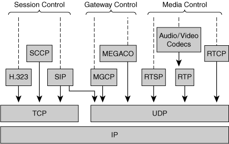
The Audio/Video Transport (AVT) working group of the Internet Engineering Task Force (IETF) developed RTP in 1996 and adopted it as a standard in RFC 1889. Subsequently, the IETF added more refinements to the protocol and republished it as RFC 3550. Always refer to the later RFC for the most current information on RTP. Figure 4-1 shows the relevance of RTP to other protocols used in IP collaboration systems.
Senders transmit RTP and RTCP packets over UDP, and the endpoints on both sides of the connection negotiate the UDP ports and IP address through the signaling protocols (H.323, Session Initiation Protocol [SIP], or Signaling Connection Control Protocol [SCCP]). The initiator of the connection provides its receive RTP port number and the IP address in the offer (or open logical channel request), and the other endpoint provides its receive RTP port number and IP address in the answer (or open logical channel response), thus establishing two-way packet communication.
Each media stream (audio, video, or data) requires a separate RTP connection on a separate UDP port. There is one minor exception to this rule: if an endpoint must send Dual Tone Multiple Frequency (DTMF) digits using the DTMF RTP payload as defined in RFC 2833. In this case, the same RTP connection can be used to send both DTMF digits and voice packets. Each RTP connection between an endpoint and a conference server is identified by
RTP receive port number of the endpoint
IP address of the endpoint
RTP receive port number of the conference server
IP address of the conference server
RTP destination ports on the receiver are always selected with even numbers. The next higher odd port number is used to carry the RTCP traffic for the associated RTP port. The latest revision of the RTP standard, RFC 3550, allows the RTP implementation to use nonadjacent port numbers for RTP and RTCP.
RTP does not provide guaranteed delivery of packets or have a mechanism to handle out-of-order packets. The RTP implementation must address these issues using RTP sequence numbers. The RTP standard comes with a companion profile that defines how each field in the RTP packets must be used. However, only one profile is of concern for the discussions in this chapter—the RTP Profile for Audio and Video Conferences with Minimal Control, first defined in RFC 1890, and later revised as RFC 3551.
Each RTP packet has three major elements:
Fixed header
Optional header extension
The media payload itself, consisting of an optional payload header, followed by the codec payload
The following subsections describes these elements. “RTP Header” describes various control fields present in the header of the RTP packet. The RTP header includes the fixed header and the optional header extension. The media payload header and the payload itself follow the RTP header.
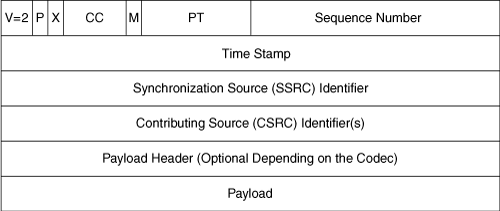
As stated in RFC 3550, the RTP header has a 12-octet mandatory part followed by an optional header extension. The header has the format illustrated in Figure 4-2.
The following sections describe the octets in the RTP header shown in Figure 4-2.
The fields in this first octet of the RTP header are described as follows:
Version (V): 2 bits—. This field identifies the version of RTP. The Version field is set to a value of 2 in most RTP implementations to denote the RTP profile defined in RFC 3551.
Padding (P): 1 bit—. If the padding bit is set, the packet contains one or more additional padding octets at the end, which are not part of the payload. The last octet of the padding contains a count of how many padding octets should be ignored, including itself. Some encryption algorithms with fixed block sizes might need padding to carry several RTP packets in a lower-layer protocol data unit.
Extension (X): 1 bit—. If the extension bit is set, exactly one header extension must follow the fixed header.
Contributing Source (CSRC) count (CC): 4 bits—. The CSRC count contains the number of CSRC identifiers that follow the fixed header. CSRC is explained in much more detail later in this chapter in the section “Contributing Source Identifiers.”
Marker (M):1 bit—. The interpretation of the marker is defined by the RTP profile in use. The M bit is intended to allow significant events such as frame boundaries to be marked in the packet stream. The M bit is helpful in video streams because it allows the endpoint to know that it has received the last packet of the frame so that it may display the full image. Without the M bit, the receiver would need to wait for one additional packet to detect a change to a new frame number.
RFC 3550 defines payload type as a 7-bit field that identifies the codec type and sample rate of media carried in the packet. When the endpoint or conference server receives an RTP packet, it uses the payload type to determine how to interpret the payload. The numeric value of the payload type may be predefined (called static payload types in the range of 0 to 96) or can be dynamically assigned during the capability negotiation between the conference server and the endpoint. There is one important distinction: For the static payload types, the clock rate is specified in the payload format. When using SIP signaling with dynamic payload types, the clock rate should be defined in the appropriate attribute line of the Session Description Protocol (SDP) offer. For example, G.711µ-Law uses a static payload type of 0, and the clock rate is defined in RFC 3551. H.264 is a dynamic payload type, and the clock rate is 90 kHz, which is specified in the SDP as follows:
m = video rtp port number RTP/AVP 97
a = rtpmap:97 H.264/90000
The sequence number is a two-octet field that identifies the order in which RTP packets were transmitted. The sequence number allows the receiver to detect packets that were dropped on the network and allows the receiver to handle out-of-order packets. The sender increments the sequence number by 1 for each RTP packet it sends. As defined in RFC 3550, the endpoint or conference server should choose the initial value of the sequence number at random, rather than starting from 0, to prevent known-value encryption attacks.
The time stamp is a 32-bit integer that increments at the media-dependent rate. As stated in RFC 3550, the time stamp reflects the sampling instance of the first octet of the media data in the RTP packet. As with sequence numbers, senders should choose a random value for the time stamp of the first packet, rather than starting at 0. The time stamp will also wrap around to 0 if it exceeds its maximum 32-bit value. The sender must transmit packets according to the real-time rate of the media, which means that if the sender issues packets with a fixed number of media samples, the delay between RTP packet transmissions should also be fixed. Table 4-1 shows audio sampling rates and their packet sizes.
Table 4-1. Sampling Rate and Time Stamps
Sampling Rate | Packet Size in RTP Time-Stamp Units |
|---|---|
Audio 10 milliseconds (ms) G.711 at 8000 Hz | 80 |
Audio 20 ms G.711 at 8000 Hz | 160 |
Audio 30 ms G.711 at 8000 Hz | 240 |
Video 30 frames per second at 90,000 Hz | 3000 (1130 * 90,000) |
Video 25 frames per second at 90,000 Hz | 3600 (1/25 * 90,000) |
In the case of MPEG bitstreams, which transmit frames out of order, the sender may transmit the RTP packets with out-of-order time stamps, but the sequence numbers will still increase. The receiver must reconstruct the data and play out the media accordingly based on the RTP time stamps. Also, note that a frame of video bitstream may be fragmented across multiple packets, which means that each packet will have the same RTP time stamp, but the sequence numbers will increase.
RTP packetization for audio codecs uses an RTP time-stamp clock that is the same as the sample clock, which means that the sampling clock increases by 1 for each sample. As a result, RTP time stamps for audio are essentially sample indexes. For example, an endpoint uses an audio codec with an 8000-Hz sample rate and an H.261 video codec. Because the sample rate of the audio stream is 8000 Hz, the RTP time stamp uses a sample clock of 8000 samples/second. If an audio stream packet has a size of 20 ms, the number of samples in that packet is 160, and therefore, the size of the packet is 160 RTP time-stamp units. H.261 uses an RTP sample clock of 90 kHz, which means a 29.97 FPS. An H.261 video stream will have a duration between frames of 33.37 ms, and the RTP time-stamp duration will equal 33.37 ms * 90,000 samples/second = 3003 RTP time-stamp units. The sender must assign RTP time stamps based on the absolute position in the source stream, which means that the RTP time-stamp sequence must account for packets not sent because of silence suppression at the sender.
The SSRC is a 32-bit field that serves as a unique identifier for an instance of an RTP stream. The originator of the RTP connection should choose this value at random. No two RTP streams within the same RTP session can have the same SSRC value. If the endpoint or the conference server changes the source IP address, the RTP packet stream must change to use a new SSRC value.
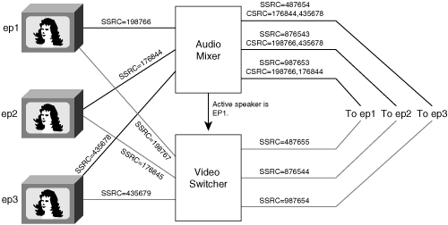
In a conference session, each endpoint transmits audio and video RTP packets to the audio mixer. The audio mixer then picks the top three or four speakers, mixes them, and sends the resulting output stream back to the endpoints. The output RTP packets should include the CSRC field, which is a list of the SSRC values of all participants selected for the mix. The audio mixer sets the CC bit in the first octet of the header to indicate the presence of a CSRC list. Many conferencing systems do not include this CSRC list because the endpoints are not conference-aware.
The RTP packetization method for the media is defined by a payload format definition, which is unique to each codec. A payload format might define a payload header, which resides in each RTP payload. The primary purpose of this header is to convey the state of the encoder to the destination. If the network drops packets, the receiver may use this state information to continue decoding the bitstream after the dropped packets. For instance, Figure 4-3 shows the format of the H.263 RTP packet.
The payload header identifies (among other things) the group of blocks (GOB), slice, or macroblock (MB) index for data at the start of the packet. It also indicates whether this packet is part of an I-frame.
The payload is the actual media data sent and received between endpoints and the conference server. The payload may contain multiple audio frames, which means that the decoder may need to parse the bitstream to determine whether the packet contains more than one frame. RTP packets generally do not contain more than one frame of video; instead, single frames of video typically fragment across multiple RTP packets.
The following shows an example of the RTP header data structure with one CSRC identifier:
typedef struct _RTP_HEADER_ {
    u8          v_p_x_cc_m;
    u8          payload_type;
    u16         seq_number;
    u32         time_stamp;
    u32         ssrc;
    u32         csrc[1];
} rtp_header_t;
The send and receive port number may be the same. For instance, the endpoint may choose to send and receive the data in port 16666. Use of the same port numbers is recommended to allow Network Address Translation (NAT) traversal. By default, endpoints use port numbers 5004/5005 (RTP/RTCP), but they can negotiate during the signaling setup to use different port numbers. Many RTP implementers have a general misconception that RTP port numbers should be above 16787, which is not true.
SSRC collision occurs if the endpoint and the conference server choose the same SSRC for their RTP streams. RFC 3550 specifies solutions for how to handle the SSRC collisions. If the conference server finds that both it and the endpoint use the same SSRC for the same session, the conference server should send an RTCP BYE packet, close the connection, and reestablish the connection using another SSRC. RFC 3350 requires that the SSRC identifiers be unique among the devices in the mixer or translator. Because the endpoints typically are not conference aware, the conference server should send the CSRC list to the endpoint so that it can detect SSRC collisions. It is up to the devices to resolve these collisions; most endpoints do not resolve them.
RFC 3550 provides the flexibility for individual implementations to extend the RTP header to add information. RTP header extensions are most useful in distributed conferencing systems. To extend the RTP header, the sender sets the X bit to 1 in the first octet of the RTP fixed header. Figure 4-4 shows the RTP header extension format.
The first 16 bits of the header extension are left open for distinguishing identifiers or parameters. The format of these 16 bits is defined by the application that adds the extension. The header extension contains a 16-bit length field that counts the number of 32-bit words in the extension, excluding the four-octet extension header. (If the RTP implementation is adding just the extension header with no actual extension, the length should be set to 0.) Only a single extension can be appended to the RTP data header.
RTP header extensions are proprietary and specific to each manufacturer. However, conference mixers may use them in ways that supplement the RTP specification to convey more information about the bitstream. For instance, some codecs such as H.263v2 need deep packet inspection to determine whether the packet carries the I-frame. Often, the conference server or the endpoint must scan for I-frames in the incoming RTP packet to render a complete picture. With RTP header extension, the endpoint or the conference server could add a simple marker in the extension to indicate to the other end whether the current frame is an I-frame. The following code snippet adds an extended RTP header to mark a specific packet as a key frame:
#define VIDEO_I_FRAME     (0x880)
typedef struct _RTP_HEADER_EXTN_ {
    struct {
        uint16  type;
        uint16  length;
    } header;
    uchar       ext_data[0];
} rtp_header_extension_t;
rtp_header_t  *rtp_hdr;
rtp_header_extension_t *hdr_x;
...............
...............
rtp_hdr -> v_p_x_cc_m |= 0x10;   /* Set the x bit in the header */
hdr_x -> type = VIDEO_I_FRAME;
hdr_x -> length = 0;   /* Since we are not adding actual extension */
RTCP is the companion control protocol for RTP. It provides periodic reports that include statistics, quality of reception, and information for synchronizing audio and video streams.
As stated in RFC 3550, RTCP performs two major functions:
It provides feedback on the quality of the media distribution. This function is performed by RTCP receiver and sender reports.
For each sender, RTCP maps RTP time stamps for each RTP stream to a common sender clock, which allows audio and video synchronization on the receivers.
RTCP carries an identifier called Canonical Name (CNAME) to identify the endpoint name associated with each RTP stream. The RTCP protocol specifies a rate-limiting mechanism for the RTCP packets, allowing RTCP to scale up to a large number of participants within the same RTP session.
Note that a general rule of thumb is that the RTCP bandwidth should not exceed 5 percent of the total RTP bandwidth used in a session.
The following sections describe the structure and functionality of the RTCP packets.
RFC 3550 defines five types of RTCP packet formats:
Sender report (SR)
Receiver report (RR)
Source description (SDES)
Membership termination (BYE)
Application-specific functions (APP)
Each RTCP packet begins with fixed headers, similar to that of RTP data packets, followed by structured elements that may be of variable length according to the packet type but that always end on a 32-bit boundary. Multiple RTCP packets may be grouped to form a compound RTCP packet. Each compound packet is encapsulated in a single UDP/IP packet for transport.
All five RTCP packet types have a fixer header followed by individual packet formats, as shown in Figure 4-5.
The following list describes the packet format:
Version (V): 2 bits—. Identifies the version of RTP, which is the same in RTCP packets as in RTP data packets. The version used in most implementations is 2, corresponding to the RTP profile defined in RFC 3551.
Padding (P): 1 bit—. If this bit is set, this RTCP packet contains some additional padding octets at the end that are not part of the control information. The last octet of the padding is a count of how many padding octets should be ignored.
Item count (IC): 5 bits—. Some RTCP packet formats contain a list of items that are specific to the packet type. This field is used by the individual packet types to indicate the number of items included in this packet.
Packet type (PT): 8 bits—. Identifies the RTCP packet type.
Length: 16 bits—. Specifies the length of this RTCP packet, excluding this header. A value of 0 is valid and indicates that this packet contains just the fixed header, consisting of the first octet.
The RTP senders (endpoints or conference server) provide information about their RTP streams through the SR packet type. SRs serve three functions:
They provide information to synchronize multiple RTP streams.
They provide overall statistics on the number of packets and bytes sent.
They provide one half of a two-way handshake that allows endpoints to calculate the network round-trip time between the two endpoints.
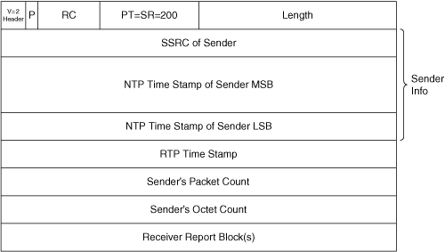
Figure 4-6 illustrates the format of the SR.
The following list explains the format:
Sender report—. The SR is identified by a packet type of 200.
NTP time stamp—. The NTP Time Stamp field is a 64-bit value that indicates the time of the RTP time stamp that is included in the report. The format of the NTP packet is a 64-bit number: the top 32 bits indicate the value in seconds, and the bottom 32 bits indicate the fraction of a second.
Note
Despite the name, Network Time Protocol (NTP) time stamps are not necessarily derived from, or generated by, an NTP time server; the name only refers to the 64-bit data format, not the NTP time server protocol. The NTP time server protocol specifies that an NTP time stamp “represents counting seconds since January 1, 1900,” but that is usually not the case for the NTP value in the RTCP packets. The NTP time stamp represents the wall clock time.
RTP time stamp—. The RTP time stamp in the header corresponds to the same instance of time as the NTP time stamp above it, but the RTP time stamp is represented in the same units of the sample clock of the RTP stream. This RTP-to-NTP correspondence allows for audio and video lip synchronization and is discussed extensively in Chapter 7,“ Lip Synchronization in Video Conferencing.”
Sender packet count—. The sender packet count indicates the total number of RTP packets sent since the stream started transmission, until the time this RTCP SR packet is generated. The sender resets the counter if the SSRC changes.
Sender octet count—. The sender octet count indicates the number of RTP payload octets sent since the stream started transmission, until the time this SR packet is generated. The sender resets the counter if the SSRC changes. This value can be used to estimate the average payload rate. The sender octet count does not include the length of the header or padding.
Receiver report block—. The RR blocks contain zero or more reception report blocks. Each reception report block conveys statistics on the reception of RTP packets from a single synchronization source depending on the number of other sources heard by the sender since the last report.
The RTP receivers (endpoints or conference server) provide periodic feedback on the quality of the received media through the RR packet type. An endpoint can use this information to dynamically adjust its transmit rate based on network congestion. For example, if a video endpoint detects high network congestion as a result of packet loss, the endpoint may choose to send at a lower bit rate until the congestion clears.
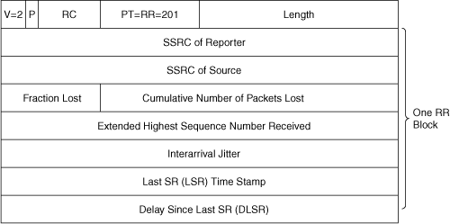
Figure 4-7 illustrates the format of the RR report, and the following list describes the fields therein.
PT=RR=201—. Indicates that the packet type is set to 201. An RR packet may contain more than one RR block. Each RR block describes the reception quality of a single synchronization source. The RR packet may have up to 31 blocks. Each report block consists of seven fields.
SSRC of reporter—. Contains the SSRC of the RR report sender.
SSRC of source—. Identifies the SSRC of the source for this report.
Fraction lost—. Identifies the fraction of RTP data packets lost since the previous SR or RR packet.
Cumulative number of packets lost—. Indicates the total number of RTP data packets from source SSRC that have been lost since the beginning of reception. This number is defined to be the number of packets expected minus the number of packets actually received, where the number of packets received includes any that are late or duplicates. The receiver discards any packets that arrive too late to play through the audio hardware, but these discarded packets are not considered dropped packets.
Extended highest sequence number received—. Indicates the highest sequence number observed in the RTP stream.
Interarrival jitter—. Estimates the statistical variance in network transit time for the RTP packets sent by the source SSRC.
Last sender report (LSR) time stamp—. Indicates the middle 32 bits out of the 64-bit NTP time stamp included in the most recent RTCP SR packet received form the source SSRC. This field is set to 0 if no SR has been received.
Delay since last SR (DLSR)—. Indicates the delay, expressed in units of 1/65,536 seconds, between receiving the last SR packet from the source SSRC and sending this RR block. This field is set to 0 if no SR packet has been received.
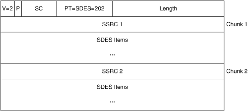
RTCP SDES packets provide participant information and other supplementary details (such as location information, presence, and so on). Figure 4-8 shows the packet format of the RTCP SDES packet.
The following list explains the format:
Payload type—. Is set to 202.
Source count (SC)—. Indicates the number of SSRC/CSRC items included in this packet.
SSRC—. Starts each chunk.
SDES—. Follows the SSRC. A list of SDES items describes that SSRC source. Each of the SDES items is of the format Type (8 bits), Length (8 bits), and Value (text of maximum 255 octets). RFC 3550 specifies several types of SDES values; the one that is more relevant for conferencing applications is CNAME.
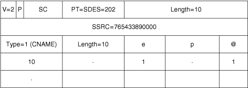
CNAME provides a canonical name for each participant that remains constant throughout the session. The CNAME should be unique among all the streams in one RTP session.
RFC 3550 requires that the CNAME be derived algorithmically and not entered manually. For example, the CNAME of an endpoint joining a conference may be [email protected]. Figure 4-9 illustrates an RTCP SDES packet from the endpoint (labeled ep in the figure) with a CNAME of [email protected].
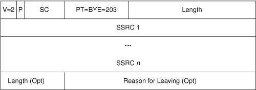
Reception of an RTCP BYE packet indicates that a participant has left a call or conference session. A BYE is also generated when an endpoint or conference server changes its SSRC. For instance, the sender must change the SSRC value in case of an SSRC collision. Figure 4-10 shows the format of the RTCP BYE packet.
Packet type—. Is set to 203.
SC—. Indicates the number of SSRC identifiers in the packet. If an endpoint sends multiple streams and leaves the session, the RTCP BYE packet from the endpoint has the SSRC of all the streams sourced by the endpoint. If a conference mixer sends the RTCP BYE packet to the endpoint, the BYE packet contains the CSRCs of the streams that the mixer was mixing.
Length—. Optional field identifies the length of the Reason field.
Reason—. Optional field indicates the reason for leaving the session.
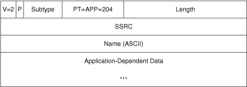
The APP packet is application-specific and is intended to be used by applications during the development phase of an RTP application. In a strict sense, RTP does not recommend the use of the APP packet for anything beyond development testing. However, one application of the APP packet is a lip sync mechanism, explained in Chapter 7. Figure 4-11 shows the packet format.
The purpose of the subtype is to group a set of APP packets under one unique name. The packet type is set to 204. The name is a four-octet ASCII string that assigns a unique name for this APP packet. The application-dependent data is a variable-length optional field that is left to the application implementation.
The conference server has multiple logical RTP devices, and each of them has different functionalities. This section looks at the functionality of these devices and how they use the RTP/RTCP headers. These devices fall into two categories: RTP translator and RTP mixer.
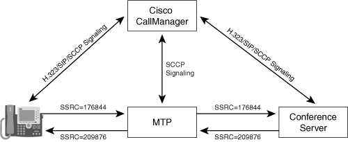
Translators have one input stream and one output stream and forward RTP packets with their SSRC identifier intact. If a translator does not change the sample rate of the stream, the translator can pass RTCP packets unchanged. If the translator alters the sample rate, however, the translator must send RTCP packets with new RTP/NTP time stamp pairs. In a conferencing system, translators take different shapes. Examples are media termination point (MTP), transcoder, and transrater.
Cisco CallManager MTPs are RTP modules (also called RTP proxies) that serve one function: They terminate and re-originate RTP/RTCP streams without processing the RTP data. Only centralized call agents, like a Cisco CallManager, use these modules. Endpoints always connect directly to CallManager at the signaling level (SIP, H.323, SCCP). However, at the media level, CallManager may either connect two endpoints directly or may insert an MTP in the media path of the connection. As far as the endpoints are concerned, the MTP appears to be the other endpoint. MTPs provide several features:
QoS support—. The RSVP protocol for bandwidth reservation requires endpoints on each side of a connection to send RSVP protocol packets on the same ports that are used for the media. If two endpoints do not support the RSVP protocol for quality of service, CallManager may connect each endpoint to an MTP, and then connect the two MTPs together, and direct each MTP to establish RSVP reservations on the RTP ports.
Call control—. MTPs add call control features (such as hold, transfer, and forward) for endpoints that do not natively support these features. Most H.323 endpoints do not support H.450, a standard for call control. As an alternative, CallManager can connect each H.323 endpoint to an MTP and then perform the call control features by rerouting RTP streams among MTPs. In this scenario, each H.323 endpoint experiences one continuous call session, but behind the scenes, CallManager rewires the MTP-to-MTP connections.
Topology hiding—. MTPs may provide topology hiding for endpoints or mixers within the private IP space of a protected network. If an external endpoint connects to an endpoint on the trusted side of a firewall, an MTP deployed in the demilitarized zone (DMZ) can terminate the RTP/RTCP media, preventing a direct connection between the external and internal endpoints. However, MTPs do not offer topology hiding for the central call agent, because external endpoints must still connect directly to CallManager to establish H.323, SIP, or SCCP signaling connections.
Conference servers do not need MTPs to handle signaling protocol conversions, such as H.323 to SIP translation, because even though the signaling protocols change, the RTP and RTCP packets remain identical between the two signaling protocols.
MTP devices do not change any of the RTP header parameters or the payload. However, the process of terminating and then reoriginating RTP media packets does consume CPU resources on a call control server. Figure 4-12 shows Cisco CallManager inserting an MTP device into the media path between an endpoint and a conference server.
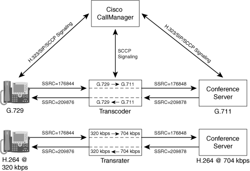
Transcoders convert RTP media from one codec to another, and transraters convert RTP media from one bit rate to a lower bit rate. For instance, if an endpoint supports only the Internet Low Bandwidth Codec (ILBC), and the conference server does not support ILBC, an audio transcoder between the endpoint and the conference server can perform the conversion.
In most implementations, audio mixers contain built-in transcoders, because the audio data must be decoded before the summation process. A transcoder is similar to a mixer with one input and one output: Each RTP header is rewritten with a new sequence number, time stamp, and other parameters. However, the SSRC stays the same. In addition, transcoders that change the code type must create new RTCP packets for the output stream.
Video conferencing systems use transraters to lower the bit rate of video or audio RTP streams. For instance, a transrater may convert high-bandwidth 704-kbps H.264 30 frames per second to low-bandwidth 320-kbps H.264 30 frames per second. Transraters handle RTP headers in the same way as RTP transcoders.
Figure 4-13 shows CallManager inserting a transcoder between the endpoint and the conference server to transcode between G.729 and G.711 audio codecs. Figure 4-13 also shows a transrater in the media path between the endpoint and the conference server. Transraters are usually built in to the conference server (or video multipoint control unit [MCU]) and not as a separate device.
An RTP mixer receives RTP packets from one or more RTP sources (such as endpoints), changes the content or format of the RTP packet, generates a new RTP packet, and sends the packet to the RTP sources. There are two models of the RTP mixer. In the first model, the endpoints are aware of being a participant in a multiway (or being in the conference) RTP session. In the second model, the mixer looks just like another endpoint to the endpoints, and the endpoints are not conference-aware. Examples of an RTP mixer include audio mixer, video MCU, and video switcher. The following sections explain the functionality of these devices.
The audio mixer is the core of the audio conferencing system. It receives the audio streams from the endpoints, mixes N + 1 separate streams, as discussed in Chapter 2, “Conferencing System Design and Architecture,” and sends the mixed streams back to the endpoints. Mixers terminate the incoming streams and create new outgoing RTP streams. There is no association between the incoming RTP header parameters (such as SSRC, sequence numbers, and time stamps) and the mixed output stream RTP parameters.
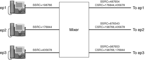
In the model where the endpoints are conference-aware, the mixer should include a CSRC list in each outgoing audio RTP packet and include the SSRC values of each participant in the mix. However, most audio mixer implementations do not add the CSRC identifiers in the outgoing packets. In addition, endpoints without robust RTP implementations might crash when trying to process a CSRC list.
Figure 4-14 shows how the mixer maps the SSRC of the incoming streams into the CSRC list of the outgoing streams.
Because each endpoint uses a different crystal clock to derive the RTP sample clock, RTP time stamps of the different incoming RTP streams are not synchronized. The mixer applies timing adjustments, adds the audio streams together, and creates new time stamps and sequence numbers for the outgoing RTP packets.
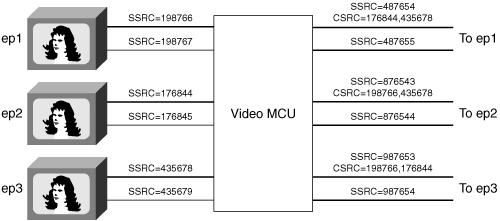
Video conference systems use video MCUs to mix audio and video streams. The video MCU typically contains tightly integrated video mixers and audio mixers. The audio mixers determine the loudest participants to select which speakers to include in the audio mix. The loudest speaker information drives a speaker selection mechanism, which is a policy that determines which video stream to include in the output mix. The video MCU sends the resulting video and audio mixes back to the participants. Because MCUs terminate and re-create audio and video RTP streams, the MCU creates new RTP headers for the output streams, with new SSRCs. Video MCUs rely on RTCP to reliably perform lip synchronization (explained in Chapter 7).
Figure 4-15 shows an MCU that decodes the video streams from three endpoints, mixes the streams, encodes, and sends back the mixed streams to the endpoints.
Current MCU implementations include both transcoders and transraters in the MCU, instead of treating them as separate RTP entities.
The video switcher gets the video streams from the endpoints, applies the conference policy to select one or more of the video streams, and sends the video streams back to the endpoints (with no transcoding, transrating, or composition). The video switcher is implemented either as an appliance that just runs this application or as part of the conference server. The video switcher is also known as a media switcher or video passthrough device.
Video switchers do not change the payload carried in the RTP streams, but rewrite the RTP headers (new SSRC, time stamp, sequence number) for the outbound RTP streams. The reason for rewriting the RTP header is because the RTP stream selected to be sent to the endpoint can be chosen dynamically.
Figure 4-16 illustrates the functionality of a video passthrough mode.
In this example of a voice-activated video conference, the video streams from the video endpoints go to the media switcher, and the audio streams go to the audio mixer. The media switcher communicates with the audio mixer to get the active speaker events. When the active speaker changes, the mixer sends an event message to the switcher, and the switcher sends the stream of that active speaker to all other endpoints in the conference. The switcher maintains the last speaker information and sends the video of the last speaker to the endpoint of the active speaker. As shown in Figure 4-16, the switcher creates a new SSRC for each outgoing video stream, and these SSRCs do not change, regardless of which input stream the switcher has selected. The switcher must not change the SSRC midstream, because endpoints might consider the SSRC change a fatal error.
As with SSRC, the media switcher keeps the time-stamp sequence continuous on the outbound video streams. When the active speaker changes, the switcher uses an input-to-output RTP time-stamp mapping that preserves the continuity of the output stream. However, any time-stamp jump in the input time stamp is reflected on the output stream.
The switcher also maintains the sequence number continuous on the outbound video streams. The only exception is for packets that arrive out of order. The switcher has to make sure that the packets that arrive out of order should also be sent out of order (and let the endpoint handle the out-of-order sequence), as shown in Figure 4-17.
This section describes the RTP payload formats for three video codecs: H.263v1, H.263v2, and H.264. The payload formats describe how the bitstream for a single frame may be fragmented across multiple RTP packets. In addition, each payload format defines a payload header, containing details such as key frame indicators. Because H.263 has largely replaced H.261, this section does not go into the details of H.261 packetization.
As discussed earlier in this chapter, each RTP packet consists of three headers: RTP header, payload header, and codec header. The RTP header and the payload header are per-packet headers, whereas the codec header is not specific to a packet but rather specific to the components of a bitstream, such as picture header, group of blocks, and so on.
As described in Chapter 3, “Fundamentals of Video Compression,” the H.263 codec has three commonly used versions. The RTP payload format for each version differs slightly and is addressed in two different RFCs: RFC 2190 defines the payload format for H.263-1996, and RFC 2429 defines the payload format for H.263-1998 and H.263-2000. Figure 4-18 shows the basic format of an H.263 packet.
The following sections describe H.263-1996, H.263-1998, and H.263-2000 in more detail. You also learn about key frame detection in H.263.
RFC 2190 defines the payload format for encapsulating H.263-1996 (H.263 or H.263v1) bitstreams in RTP packets. For this version, the payload format defines three modes for the H.263 payload header: mode A, mode B, and mode C. An RTP packet can use one of these three modes, depending on the desired packet size and the encoding options used in the H.263 bitstream. The F and P fields in the payload header determine the mode. The endpoints and the conference servers must be prepared to receive packets in any mode. These modes are not negotiated in the SDP offer/answer.
The next sections describe the three H.263 modes.
In mode A, an H.263 payload header of 4 bytes is present before the actual payload, as shown in Figure 4-19. Note that mode A packets always start with a picture code or a GOB start code.
Table 4-2 explains the different bit fields.
Table 4-2. H.263-1996 Mode A Bit Fields
Bit Field | Size (in Bits) | Description |
|---|---|---|
F | 1 | Indicates the mode of the payload header. A value of 0 indicates mode A; a value of 1 indicates mode B or mode C. |
P | 1 | When F=1, a P bit value of 0 indicates mode B, and a value of 1 indicates mode C. |
SBIT | 3 | Start bit position. Specifies the number of most significant bits ignored in the first byte. |
EBIT | 3 | End bit position. Specifies the number of least significant bits ignored in the last data byte. |
SRC | 3 | Specifies the resolution of the current picture. |
I | 1 | Set to 0 for an intracoded frame and to 1 for intercoded. |
U | 1 | Set to 1 if the Unrestricted Motion Vector option, bit 10 in PTYPE defined by H.263, was set to 1 in the current picture header otherwise, set to 0. |
S | 1 | Set to 1 if the Syntax-based Arithmetic Coding option, bit 11 in PTYPE defined by H.263, was set to 1 in the current picture header; otherwise, set to 0. |
A | 1 | Set to 1 if the Advanced Prediction option, bit 12 in PTYPE defined by H.263, was set to 1 in the current picture header; otherwise, set to 0. |
R | 4 | Reserved: These bits must be set to 0. |
DBQ | 2 | Differential quantization (DBQ)—the value should be the same as DBQUANT defined by H.263. Set to 0 if the PB-frames option is not used. |
TRB | 3 | Temporal Reference for the B frame as defined by H.263. It is set to 0 if the PB-frames option is not used. |
TR | 8 | Temporal Reference for the P-frame as defined by H.263. It is set to 0 if the PB-frames option is not used. |
Example 4-1 shows the Ethereal capture of an H.263v1 mode A frame. Note that the F bit is set to 0.
Example 4-1. H.263 Ethereal Packet Trace
Frame 4733 (1327 bytes on wire, 1327 bytes captured)
Ethernet II, Src: 00:14:38:be:ec:57, Dst: 00:13:20:12:b5:5d
Internet Protocol, Src Addr: 172.27.75.146 (172.27.75.146), Dst Addr:
  172.27.75.187 (172.27.75.187)
User Datagram Protocol, Src Port: 21468 (21468), Dst Port: 5445 (5445)
Real-Time Transport Protocol
   10.. ....=Version: RFC 1889 Version (2)
   ..0. ....=Padding: False
   ...0 ....=Extension: False
   .... 0000=Contributing source identifiers count: 0
   0... ....=Marker: False
   .010 0010=Payload type: ITU-T H.263 (34)
Sequence number: 59
Timestamp: 117123
Synchronization Source identifier: 2887470011
ITU-T Recommendation H.263 RTP Payload header (RFC2190)
   F: False
p/b frame: False
Start bit position: 0
End bit position: 0
SRC format: CIF 352x288 (3)
Inter-coded frame: True
Motion vector: False
Syntax-based arithmetic coding: False
Advanced prediction option: False
Reserved field: 0
Differential quantization parameter: 0
Temporal Reference for B frames: 0
Temporal Reference for P frames: 0
H.263 stream: 000081DA0E043FFFFC03958989935EC9AF76C8B3A07FFFFF...
In mode B, an H.263 bitstream can be fragmented at MB boundaries. Whenever the packet starts at an MB boundary, this mode is used without the PB-frames option. Figure 4-20 shows the mode B payload header.
The fields F, P, SBIT, EBIT, SRC, R, I, U, S, and A are defined as in mode A. The F bit should be set to a value of 1, and the P bit should be set to a value of 0. Table 4-3 explains the remaining fields.
Table 4-3. H.263-1996 Mode B Fields
Bit Field | Size | Description |
|---|---|---|
QUANT | 5 | Quantization value for the first MB coded at the beginning of the packet. Set to 0 if the packet begins with a GOB header. |
GOBN | 5 | GOB number in effect at the start of the packet. GOB numbers are specified differently for different resolutions. Refer to RFC 2190 for details. |
MBA | 9 | Macroblock address (MBA)—the address within the GOB of the first MB in the packet, counting from 0 in scan order. For example, the third MB in any GOB is given MBA = 2. |
HMV1 | 7 | Horizontal motion vector predictors for the first MB in this packet. |
VMV1 | 7 | Vertical motion vector predictors for the first MB in this packet. |
7 | Horizontal motion vector predictors for block number 3 in the first MB in this packet when four motion vectors are used with the advanced prediction option. This information is needed because block number 3 in the MB needs different motion vector predictors than other blocks in the MB. These two fields are not used when the MB has only one motion vector. Refer to RFC 2190 for block organization in an MB. | |
VMV2 | 7 | Same as HMV2, except that this entry is for vertical motion vector predictors. |
In mode C, an H.263 bitstream is fragmented at MB boundaries of P-frames if those P-frames have the PB-frames option set. This mode is intended for GOBs whose sizes are larger than the maximum packet size allowed in the underlying protocol when the PB-frames option is used. The F bit is set to 1, and the P bit is set to 1 to indicate mode C. Figure 4-21 shows the mode C payload header.
The bit fields are defined the same as in mode A and mode B. The only exception is the 19-bit RR field—these bits are reserved and are set to 0.
Most H.263 endpoint implementations use mode A because of its simplicity and small payload header.
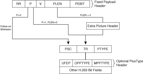
RFC 2429 defines the payload header format for H.263+ (also known as H.263-1998) and H.263++ (also known as H.263-2000) codecs. These codecs are also referred to as H.263v2. The payload header consists of a mandatory fixed part of two octets followed by a variable-length optional header. Figure 4-22 shows the packet structure.
Table 4-4 explains the different bit fields used in the payload header.
Table 4-4. H.263v2 Payload Header Format
Bit Field | Number of Bits | Description |
|---|---|---|
RR | 5 | Reserved—set to 0. |
P | 1 | Indicates a picture start, or a picture segment (GOB/slice) start, or a video sequence end. |
V | 1 | Indicates the presence of a one-octet field containing information for Video Redundancy Coding (VRC). |
PLEN | 6 | Picture header length—length in bytes of the extra picture header. If no extra picture header is attached, PLEN is 0. The length excludes the first two octets of the fixed header. |
PEBIT | 3 | Indicates how many bits are ignored in the last byte of the picture header. |
VRC is an optional mechanism intended for error resiliency in packet networks. If V is set to 1, a 1-byte header is attached immediately after the 2-byte fixed payload header.
If P is set to 0, this packet indicates a follow-on stream, meaning that it does not include the start of a picture or a slice. If P is set to 1, this packet contains the start of a picture or a slice. (2 bytes of 0 bits then have to be prefixed to the payload of such a packet to compose a complete picture, GOB, slice, end of sequence [EOS], or end of sub-bit stream [EOSBS] start code.)
The packet may contain an optional extra picture header, which is indicated by a nonzero PLEN value. Encoders add extra picture headers to provide greater error resilience. The value of PLEN indicates the size of the extra picture header.
The actual payload data for each picture consists of an optional picture header, followed by data for a GOB or slices, eventually followed by an optional end-of-sequence code, followed by stuffing bits. As shown in Figure 4-22, the picture header starts with a picture start code (PSC).
Table 4-5 explains the fields of the PSC for the H.263v2 codec
Table 4-5. H.263v2 Picture Header Format
Bit Field | Number of Bits | Description |
|---|---|---|
PSC | 22 | Picture start code. If the packet contains the picture or slice, the value is 0000 0000 0000 0000 1 00000. This field should be byte-aligned. |
TR | 8 | Temporal reference. This value increases by 1 for each new frame and then wraps around to 0. |
PTYPE | Variable length | Picture type—information about the complete picture. |
PTYPE has 13 bits and carries a variety of information. Bit 9 indicates the picture coding type and determines whether the packet carries a key frame (value 0) or P-frame (value 1). If bits 6–8 of the PTYPE field are set to 111, an extended header called a PlusType header is added to the payload header. If the PlusType header is added, bit 9 no longer indicates whether the packet carries a key frame, and this I-frame information is instead added to the PlusType header.
The PlusType header consists of the following three fields:
Update Full Extended PTYPE (UFEP) of 3 bits.
Optional Part of PlusType (OPPTYPE) of 18 bits.
Mandatory Part of PlusType (MPPTYPE) of 9 bits. The first 3 bits of MPPTYPE indicate the picture type code (I-frame, P-frame, PB-frame, and so on). If the first 3 bits contain a value of 000, the current frame is an I-frame.
Video MCUs have a tricky requirement: They must be able to create a seamless output stream for each endpoint, while at the same time switching between multiple input streams based on the loudest speaker floor control policy. The problem is that if the MCU were to switch immediately to a new input stream, endpoints receiving that output stream would detect a discontinuity in the bitstream and would have to wait for a key frame from the new selected stream to resume decoding the stream. To make the output stream appear seamless, the MCU should delay the switch to a new input stream until a key frame arrives from that new input stream. The receiving endpoint detects the discontinuity, but it does not have to wait for a key frame, because the MCU provides a key frame immediately after the switch. The video encoders, depending on the codec and packetization, set bits in the RTP payload header to indicate the presence of an I-frame.
In H.263v1, an I bit in the RTP payload header indicates that the packet belongs to an I-frame. For H.263 mode A, a value of 0 in the twelfth bit from the start of the payload header indicates that the packet belongs to an I-frame. For mode B and mode C, a value of 1 in the thirty-third bit from the start of the payload header indicates that the packet belongs to an I-frame.
With H.263v2, the MCU must resort to deep packet inspection of the codec bitstream to identify the start of an I-frame. The H.263 PSC indicates the I-frame in one of two places, depending on the contents of the PTYPE field:
Bits 6–8 of PTYPE != 111—. A value of 0 in bit 9 indicates an I-frame.
Bits 6–8 of PTYPE == 111—. A value of 0 in bits 1–3 of the MPPTYPE field indicates an I-frame.
H.264 is a video codec that delivers visual quality superior to H.263 at the same bit rates. H.264 is also referred to as Advanced Video Coding (AVC). H.264 consists of two separate definitions:
The video coding layer (VCL)
The network abstraction layer (NAL)
The VCL represents the video content, and the NAL defines the packetization format for transport protocols such as RTP. All data is contained in NAL units. The H.264 bitstream can be of two formats: NAL unit stream and byte stream format. We limit our discussion to the NAL unit stream as specified in RFC 3984.
Figure 4-23 shows the format of a NAL header, which is the basic structure of an H.264 RTP packet. Per RFC 3984, all H.264 RTP packets contain the 1-byte NAL header field after the RTP header.
Table 4-6 explains the bit fields.
Table 4-6. NAL Header Bit Fields
Bit Field | Size (in Bits) | Description |
|---|---|---|
F | 1 | Forbidden_zero_bit. A value of 1 indicates that the payload may contain errors or syntax violations. H.264 implementations usually drop packets that have the F bit set to 1. A value of 0 indicates that the payload should not contain any error or syntax violations. |
NRI | 2 | NAL_ref_idc. A value of 00 indicates that the content of the NAL unit does not contain information needed to reconstruct reference pictures for inter-picture prediction. A value of greater than 00 indicates that the receiver must decode the NAL unit to reconstruct other inter-codec pictures. |
TYPE | 5 | This field identifies the type of the NAL unit carried by the packet. A value of 0 is undefined. |
The Type field defines the packetization mode, as shown in Table 4-7.
Table 4-7. NAL Header Type Field Values
Type | Packet | Description |
|---|---|---|
0 | Undefined | — |
1–23 | NAL unit | Single NAL unit packet. |
24 | STAP-A | Single-time aggregation packet |
25 | STAP-B | Single-time aggregation packet |
26 | MTAP-16 | Multi-time aggregation packet |
27 | MTAP-24 | Multi-time aggregation packet |
28 | FU-A | Fragmentation unit |
29 | FU-B | Fragmentation unit |
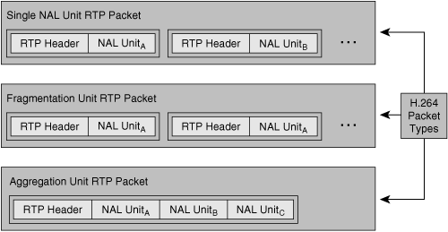
The NAL unit type field indicates the type of the packet (and thus the structure of the RTP packet). There are three possible types:
Single NAL unit (SNALU)—. This packet type contains only a single NAL unit as indicated by the type value of 1-23. The H.264 codec specification describes each type value in detail.
Aggregation packet—. This packet type aggregates multiple NAL units into a single RTP payload. There are four versions of this packet, corresponding to type values 24-27.
Fragmentation unit (FU)—. This packet type fragments a NAL unit over multiple RTP packets. There are two versions of this packet (type values 28 and 29).
Figure 4-24 shows the three possible H.264 packet types.
The following sections describe the three NAL unit packet types in more detail.
The SNALU payload type contains only a single NAL unit in the payload. Figure 4-25 shows the format of the SNALU. It contains a 1-byte header (the fields are explained in Table 4-6 in the preceding section). The value of the Type field is in the range of 1 to 23.
NAL units must be transmitted in the same order as their NAL unit decoding order, and the RTP sequence number should reflect this transmission order.
RFC 3984 defines two basic types of aggregation packets:
Single-time aggregation packet (STAP)
Multi-time aggregation packet (MTAP)
The STAP and MTAP packets must not be fragmented and should be contained within a single RTP packet. MTAP is not commonly used for video conferencing.
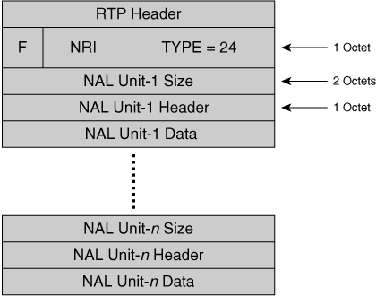
STAP aggregates NAL units with identical NALU-time. NALU-time is the value that the RTP time stamp would have if that NAL were transported in its own RTP packet. RFC 3984 defines two types of STAP packets:
STAP-A—. NAL units in the aggregation packet share the same time stamp and appear in valid decoding order.
STAP-B—. NAL units in the aggregation packet share the same time stamp and may not be in the correct decoding order.
Figure 4-26 shows the packet format of the STAP-A packet. The value of the Type field in the NAL header is set to 24. The Size field (two octets) indicates the size of the NAL unit in bytes, which includes the NAL unit header plus data.
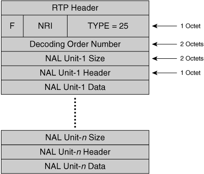
Figure 4-27 shows the format of the STAP-B packet. The type field is set to a value of 25. The STAP-B packet consists of a two-octet decoding order number (DON) that indicates the NAL unit decoding order. The DON is required because the transmission order and the decoding order might differ, and the DON indicates the decoding order.
MTAP aggregates NAL units with potentially different NALU times. RFC 3984 defines two types of MTAP packets:
MTAP-16 (16-bit time-stamp offset)
MTAP-24 (24-bit time-stamp offset)
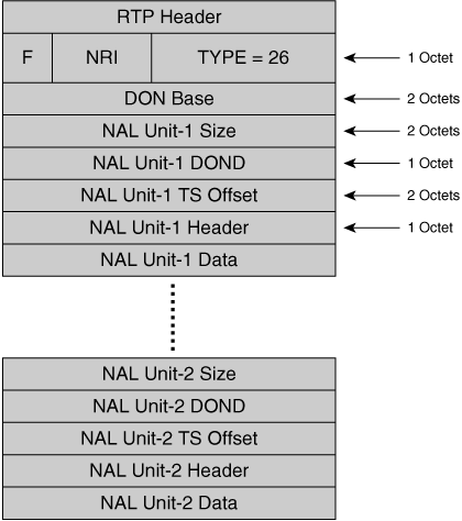
Figure 4-28 shows the packet format of MTAP-16.
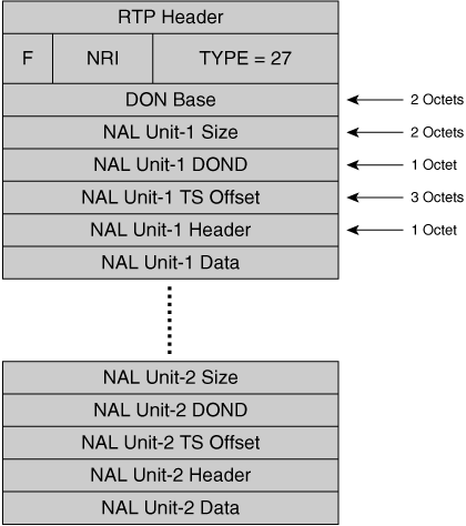
The Type field is set to a value of 27.
The payload header contains a two-octet decoding order number base (DONB). The MTAP packet contains multiple NAL units. The DONB contains the value of DON for the first NAL unit in the MTAP packet.
Figure 4-29 shows the packet format of MTAP-16. The Type field is set to a value of 27.
The choice between MTAP-16 and MTAP-24 is application-dependent. The only difference between the two packet formats is the length of the time-stamp offset field.
The fragmentation unit (FU) allows a sender to fragment a single NAL unit into several RTP packets. The sender of the FU packet must send the fragments in consecutive order with ascending RTP sequence numbers. The receiver should reassemble the NAL unit according to the same RTP sequence number. The RTP time stamp of an RTP packet carrying an FU is set to the NALU time of the fragmented unit.
RFC 3984 defines two types of fragmentation unit packets. Figure 4-30 shows the FU-A packet format, which consists of a one-octet NAL header, followed by a one-octet FU header, followed by FU payload.
Table 4-8 summarizes the Fragmentation Unit header fields.
Table 4-8. H.264 Fragmentation Unit Packet Header Fields
Size (in Bits) | Description | |
|---|---|---|
S (start) | 1 | The Start bit indicates the start of the fragmented NAL unit payload. When the following FU payload is not the start of a fragmented NAL unit payload, this bit is set to 0. |
E (end) | 1 | The End bit indicates the end of a fragmented NAL unit. This bit is set to 0 otherwise. |
R (reserved) | 1 | The sender must set this bit to 0, and the receiver must ignore this bit. |
Type | 5 | The value should be set according to Table 7-1 of the H.264 ITU spec. |
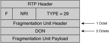
Figure 4-31 shows the packet format of the FU-B packet. The packet structure of an FU-B packet is similar to that of an FU-A packet, except for the presence of a DON field.
If a NAL unit can fit into a single FU, the NAL unit should be fragmented. In other words, the fragmented NAL unit must not be transmitted in one FU, which means that the Start and End bit of the FU header cannot be set to 1 in the same FU packet. If a fragmentation unit is lost, the receiver should discard all remaining FUs of that NAL unit.
Key frame detection with H.264 packets is straightforward. Table 4-9 summarizes the steps to detect a key frame for each packet type.
Table 4-9. H.264 Key Frame Detection for Different Packet Types
Packet Type (as Indicated by the Type Field in the NAL Header) | Steps to Detect the Key Frame in the NAL Header |
|---|---|
SNALU (type value between 1 and 23) | The packet contains a key frame if the Type field within the NAL header contains a value of 5 (coded slice of an IDR picture). |
If (type == 24), skip the next 3 bytes (NAL header and size) and go to the NAL unit header. | |
If the Type field of the NAL unit header contains a value of 5, the packet carries a key frame. | |
STAP-B | If (type == 25), skip the next 5 bytes (NAL header, DON, and size) and go to the NAL unit header. |
If the Type field of the NAL unit header contains a value of 5, the packet carries a key frame. | |
MTAP-16 | If (type == 26), skip the next 8 bytes (NAL header, DON base, size, DOND, and TS offset) and go to the NAL unit header. |
If the Type field of the NAL unit header contains a value of 5, the packet carries a key frame. | |
MTAP-24 | If (type == 27), skip the next 9 bytes (NAL header, DON base, size, DOND, and TS offset) and go to the NAL unit header. |
If the Type field of the NAL unit header contains a value of 5, the packet carries a key frame. | |
FU-A | If (type == 28), skip the next 3 bytes and go to the NAL unit header. |
If the Type field of the NAL unit header contains a value of 5, the packet carries a key frame. | |
FU-B | If (type == 29), skip the next 1 byte and go to the FU unit header. |
If the Type field of the FU header contains a value of 5, the packet carries a key frame. |
Conference server components must handle endpoint failures properly. Signaling protocols might provide some failure information, such as the SIP session-expires header. However, the media plane of the entire conferencing architecture must ensure that a backup mechanism detects and handles an endpoint failure in mid-session. The two common mechanisms to handle such scenarios are Internet Control Message Protocol (ICMP) unreachable messages and RTP inactivity timeout messages.
If the application in the endpoint fails (for example, the endpoint closes the RTP port it is listening to), the conference server might get ICMP unreachable messages from the endpoint IP stack for the packets it is sending to the endpoint. Upon detecting that, the conference server can close the RTP/RTCP channels and initiate the termination of the signaling relationship with the endpoint and recover the audio and video ports. Using ICMP to detect the endpoint failure is not a reliable method, because firewalls sometimes filter out all ICMP packets.
Some implementations use RTP timeouts to handle the cases of endpoint crashes or failures. The conference server starts an RTP inactivity timer for each RTP session to the endpoint. If the server receives any RTP packets while the timer is running, the server restarts the timer. If the timer expires, the server assumes that the endpoint is dead. However, server implementations must consider whether some endpoints may be in receive-only mode, or whether an endpoint has silence suppression activated. Both of these scenarios inhibit RTP packet transmission.
If endpoints support RTCP, reception of an RTCP packet might indicate that the endpoint is still alive.
This chapter has described the fundamentals of RTP/RTCP protocol formats and their application to conferencing systems. The chapter covered the different types of RTP devices used in conferencing systems and their functionalities. The chapter also discussed the payload formats, packet types, and key frame detections for common video codecs. The chapter concluded with a brief explanation of stream loss detection with ICMP unreachable messages and RTP inactivity timeout messages.
Bormann, C., J. Ott, G. Sullivan, S. Wenger, C. Zhu, L. Cline, G. Deisher, T. Gardos, D. Newell, and C. Maciocco. IETF RFC 2429, RTP Payload Format for the 1998 Version of ITU-T Rec. H.263 Video (H.263+). October 1998.
ITU-T Recommendation H.264, Series-H audio visual and multimedia system, May 2003.
Schulzrinne, H., S. Casner, R. Frederick, and V. Jacobson. IETF RFC 3550, RTP: A Transport Protocol for Real-Time Applications. July 2003.
Wenger, S., M. M. Hannuksela, T. Stockhammer, M. Westerlund, and D. Singer. IETF RFC 3984, RTP Payload Format for H.264 Video. February 2005.
Zhu, C. IETF RFC 2190, RTP Payload Format for H.263 Video Streams. September 1997.

