Networks have become a pervasive element of everyday life. Even though they can adopt different physical characteristics and carry diverse payloads, they all share a common set of fundamental attributes. The essence of a network is the fact that it connects or relates objects or devices.
The instantiation of this connection can adopt many forms. It can be intangible, as is the case in an organizational or relational network, or it can be tangible. Examples of tangible networks include a highway system, an electrical grid, and data communications networks. These types of networks are designed and built to interconnect nodes so that objects can be moved between source and destination. The highway system permits people and goods to be moved between any two points by means of a meshed infrastructure of roads. The electrical grid transports electrons between the power generating plants and the points of consumption. Finally, data communications networks carry information—that is voice, video, or data—from respective sources to destinations. The definitions of source and destination are purposely left open because they include people in addition to mechanical and electronic machines.
The Business Case for Enterprise-Class Wireless LANs focuses on a specific subset of data networks, namely wireless local area networks (WLANs). As such, from here on you shall see the term network refer exclusively to data communications networks.
This chapter introduces you to the value of mobility in data communications. Various scenarios are presented to briefly illustrate the socioeconomic benefits of mobility solutions. This chapter focuses on helping you develop an understanding of WLAN technology. We illustrate the OSI framework and how WLANs relate to other internetworking technologies that include LAN, WAN, and mobile cellular solutions. The framework will also help position the WLAN-specific concepts that are covered throughout the remainder of this chapter.
Information has become the engine of our society. It forms the basis of entire industries as in services, media, and advertising. Information provides a competitive advantage to other industries such as financial services, manufacturing, and transportation. Government uses information to preempt and address security threats. The entire educational system is based upon information transfer to pupils. Finally, information is a means of relaxation and entertainment for many of us. Literature, music, television, and movies are in their most abstract form sources of information. As such, information’s value and uses are tremendously varied and exceptionally wide in scope.
Over time, businesses and people have come to want and expect accessibility to their source of information where they want it, when they want it, and how they want it. The digital revolution has brought us one step closer to this reality. It not only spawned an entire new industry—the information technology industry—but literally disrupted how society conducts business, functions, and entertains itself. Many of us today are spending our professional lives trying to leverage information and technology to create new value propositions, capture efficiencies and cost savings, and increase productivity.
In his 1995 book Being Digital, Nicholas Negroponte, director of the Massachusetts Institute of Technology’s Media Laboratory, foresaw that the digital revolution would be a catalyst for a digital flip.[1] Negroponte postulated that content that was traditionally delivered via terrestrial channels would be flipped onto wireless channels. An example is telephony. At the same time, content that was typically delivered via wireless channels would be migrated onto terrestrial carriers. For example, television used to be delivered via radio or satellite. Today, cable-based systems are displacing the wireless distribution medium for television. Hence, there is a flip between delivery mechanisms for content. With many different kinds of digital technologies maturing at breakneck speeds, the opportunity arose to realign the accessibility to information. Indeed, information can be roughly categorized into two types:
Information we want access to anywhere and anytime—. Cellular mobile voice communications is a prime example. Its explosive growth in terms of technologies and consumer adoption rates supports the case of a large demand for anywhere and anytime access to information.
Information we consume in fixed locations—. An example would be television. Most of us do not watch television while on the move. We watch TV at home, in a hotel room, or in a lounge. We do not necessarily require mobility for television because we tend to associate it with relaxation and sitting down.
Note
At the time of writing, various initiatives are underway to provide high-mobility video solutions to consumers. The strategy is to implement video-streaming by means of next-generation cellular technologies or by extending portable music players with video capabilities. It will be interesting to follow the uptake and success of these mobile video solutions.
You could argue that people want to be able to watch television anywhere and anytime. The key word to focus on in this case is anywhere because storage technologies (for example, VCRs, recordable DVDs, and DVRs) have all but made obsolete the notion of anytime. When you consider televisions, the prime parameters that come to mind are screen size, picture quality, and price. Mobility is most likely not on the radar. It simply does not have a high value-proposition in the case of television. This fact supports the low adoption rate of portable televisions. Similarly, the very high adoption rate of mobile phones, although somewhat unexpected, does stand to reason. As such, you can make a valid distinction between applications that demand mobility and those that do not or do so to a very low degree.
In the same way that cellular technologies have extended the Plain Old Telephone Systems (POTS) beyond the boundaries of the wired infrastructure, WLANs extend data communications networks beyond traditional physical boundaries. The implications are vast and complex. Management guru Dr. Clayton Christensen coined the term disruptive technology in his book The Innovator’s Dilemma. Christensen defined a disruptive technology as a new technological innovation, product, or service that eventually overturns the existing dominant technology in the market. This occurs despite the fact that the disruptive technology is both radically different from the leading technology and that it often initially performs worse than the leading technology according to existing measures of performance. A disruptive technology thus effectively comes to dominate an existing market either by filling a role in a new market that the older technology could not fill or by successively moving up-market through performance improvements until finally displacing the market incumbents.
Applying Christensen’s definition, wireless networks are truly a disruptive technology. They are fueling growth in companies, capturing efficiencies, boosting productivity, and causing entire industries to rethink their business strategies.[2]
The prime benefit of WLANs is that they enable information to be moved through the ether to the point where it is required. There is no need for hardwiring. There is also no need for line-of-site, a barrier for infrared communication technology. As such, WLANs provide an extendable, totally transparent means for interconnecting entities. These entities can be personal computers (PCs), personal digital assistants (PDAs), phones, sensors, radio frequency identification (RFID) tag transceivers, and many more. In theory, any device that can house a radio transmitter and the appropriate software is a candidate for becoming a WLAN node. Given the traits of transparency and the ability to connect heterogeneous types of devices, it is important to understand the strengths and limitations of WLANs to correctly align business or personal goals and technological solutions.
The next section provides a baseline high-level technical overview of WLANs. We compare WLANs’ positioning to other networking technologies and introduce WLAN components, their inner workings, and operational implications. Even though this chapter is comprehensive, it is not exhaustive and does not describe all the technical intricacies of WLAN technology.
Let us start with the idea that complex problems are usually broken down into modular components to facilitate understanding and to make the solution more tractable. For this purpose, data communications make use of the Open Systems Interconnection (OSI) reference model. Given the extensive coverage of this model available in other books, this book does not intend to provide a complete and exhaustive overview of the OSI reference model. Instead, this section provides a brief summary of the model and focuses on the sections that are most relevant within the context of this book.
Note
The OSI model was defined by the International Organization for Standardization (ISO) and was conceived to allow interoperability across the various platforms offered by vendors. A provisional version of the model was first published in March 1978 and became standardized in 1979 after some minor refinements.
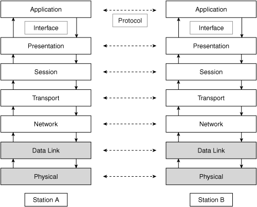
The OSI model breaks the overall task of communication into layers that focus on relatively delimited and well-defined subtasks. Within this framework, two types of communication occur:
Interface—. Layers communicate with their neighbors through an interface. A layer presents or receives information from its respective adjacent layers in a standardized format through this interface.
Protocol—. The second type of communication is with a peer layer by means of a protocol. Peer layers are at the same level but in different nodes. As such, network nodes can communicate directly on a layer-by-layer basis with other network nodes. However, the semantics of this communication are restricted to each layer.
The seven layers that make up the OSI reference model and the two communication types are illustrated in Figure 1-1.
Note
The number seven has no specific meaning or purpose. The ISO defined the OSI reference model and subsequently tasked subcommittees to work out the details for each layer.
The following sections provide more detail on each of the respective OSI layers.
The purpose of the physical layer is to perform the actual transmission of information across a link. As such, it covers characteristics that are related to the physical properties and distinctiveness of the network. This includes the transport medium, topology, data encoding techniques, transmission speeds, maximum transmission distances, voltage levels, connectors, pin functions, conversion of information into signals, and synchronization. The physical characteristics that are most important in the context of this book are the transport medium, the topology, and the data encoding techniques. An overview of each follows.
The transport medium defines the type and characteristics of the physical channel that carries information. In its strictest sense, the channel is used as a tunnel for electricity or electromagnetic waves. For the purpose of this book, this section makes the distinction between electrical, optical, and radio channels.
An electrical channel makes use of copper wires to conduct electrons or electricity from source to destination. An optical channel employs a fiber optic cable to guide light between the emitter and the receiver. Finally, a radio frequency (RF) channel utilizes the radio band of the electromagnetic spectrum to carry signals. A key difference of RF is that the RF channel is not bounded or confined to the actual physical systems but relies on the free space of air.
Indeed, RF is truly unbounded because the ether has no borders. Because RF signals are not guided by a conduit, they can theoretically propagate in any direction. This borderless characteristic of RF has two important implications:
External influences have a greater impact on unbounded signals and their properties because the lack of a conduit implicitly prevents shielding from external influences.
Radio communication is always a broadcast in the sense that any device can tune into the signal.
The broadcast nature of radio communication has important implications for both WLAN technology and applications. For example, transmissions can inherently be intercepted by any network-attached station. When combined with nondirectional antennas, every station intercepts every transmission of every other station. Not only does this have security implications, but it also requires methods for resolving orderly access to the air. These implications will be covered in greater detail in Chapter 7, “Security and Wireless LANs.”
The following list describes the four basic topologies for networks consisting of three or more nodes:
Figure 1-2 illustrates the different topologies.
By construction, WLANs adopt a bus topology because they use radio as their transmission channel. The radio spectrum forms the bus, and every node always hears every transmission from every other node. This is only true for a bus topology. Confusion might arise due to the physical layout of WLANs.
The access point (AP), which acts as a bridge, forwards all data it receives. The impression arises that WLANs adopt a star topology. However, star topologies provide singular and dedicated connectivity between the stations and the central hub, which is not the case for WLANs. In WLANs, the transport medium is shared among all connected stations. Hence, a distinction must be made between the physical appearance of a star topology and the logical layout and behavior as a bus topology.
Data encoding is the transformation of information into a form that is suitable for the transmission medium. Adverse transmission effects such as attenuation, distortion, and interference are taken into consideration when selecting an encoding method for a particular physical channel.
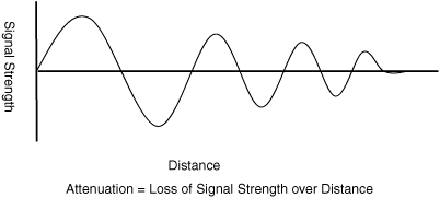
Attenuation is the loss of signal strength. This can be due to impurities of the transmission medium. Copper has a natural resistance at room temperature. Similarly, fiber optic cables contain impurities that reduce signal strength with distance. With regard to radio signals, one cause of loss of signal power is materials that the signal encounters. The encountered materials cause absorption or reflection resulting in a reduction of signal strength (see Figure 1-3). For example, water absorption bands are 22, 183, and 323 GHz, and the oxygen absorption regions are 60 and 118 GHz.
Another cause of attenuation of radio signals is the increasing volumetric spread of the signal as the distance from the source increases. Incoherent electromagnetic waves—as opposed to coherent electromagnetic waves such as lasers—lose signal focus in function of the distance traveled. The loss of focus corresponds with a loss in power as the power is distributed over a greater area. This effect can clearly be seen in flashlights. With constant power levels of the source, the beam’s footprint increases and the intensity of the light decreases the farther you are away from the source.
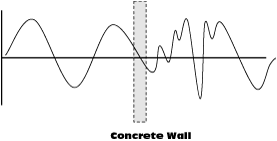
Distortion is the process of the physical medium influencing frequency components of the original signal in different ways. The amount of resistance that a physical entity has on a signal medium is partly determined by the frequency of the signal that passes through it. Different materials affect the RF signal at different levels. The effect of lead versus glass on a low-frequency signal will be different from a high-frequency signal. The result is an undesirable change in the shape of the radio wave or distortion of the signal that increases with transmission distance (see Figure 1-4).
Note
Common definitions of the frequency band groups are low, high, and ultra-high. Low bands range from 0 to 30 MHz, high bands from 100 to 300 MHz, and ultra-high bands from 300 MHz to 3 GHz.
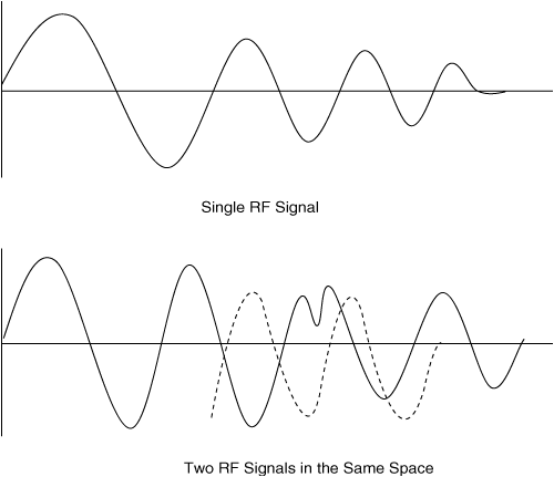
Interference occurs as a result of outside influences. In copper, inductive currents created by external electromagnetic fields mutate the original signal’s character. Sometimes referred to as noise, in RF, interference is actually the disturbance of one radio signal by another of the same frequency. The various transposed signals either boost or reduce frequency components of the original signal, leading to modification of the original signal’s profile. Figure 1-5 shows both the single undisturbed RF wave and the RF wave when another is introduced. The second diagram shows that when the other wave is added, it “interferes” with the original wave.
Data encoding techniques are used to construct a robust, reconstructable signal for the given medium. The techniques not only define how digital information is encoded into and decoded from respective electrical, optical, or radio signals, but also provide methods for error detection and correction.
The role of the data link layer is to provide reliable transit of data across a physical link. Specifications define physical addressing, sequencing of frames, flow control, and error notification. Error notification alerts upper-layer protocols that a transmission error has occurred. Sequencing of data frames reorders frames that are received out of sequence. Finally, flow control moderates the transmission of data so that the receiving device is not overwhelmed with more traffic than it can handle at any given time.
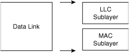
IEEE has subdivided the data link layer into two sublayers:
Logical Link Control (LLC)
Media Access Control (MAC)
Figure 1-6 illustrates the IEEE sublayers of the data link layer.
The LLC sublayer manages communications between devices over a single link of a network. LLC is defined in the IEEE 802.2 specification and supports both connectionless and connection-oriented services used by higher-layer protocols. IEEE 802.2 defines a number of fields in data link layer frames that enable multiple higher-layer protocols to share a single physical data link.
The MAC sublayer defines the contention resolution method for access to the physical medium. In addition, the MAC specification defines MAC addresses that, at the data link layer, uniquely identify devices.
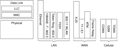
The combination of Layer 1 and MAC specifications define the type of LAN network.
WAN standards are typically defined solely by their Layer 1 characteristics. The same is true for cellular communications standards. For example, a T1/E1 network is defined by its underlying Layer 1 (physical) network.
Figure 1-7 illustrates the OSI positioning of various common networking standards.
Given the lesser importance of Layers 3 to 7 in the context of this book, a brief overview is provided for the remaining OSI layers. Consult other books, such as the following, if you would like in-depth coverage of these respective layers:
Layer 3 supports network addressing, route selection, congestion control, and packet fragmentation and reassembly. IP is today’s most commonly employed network layer protocol.
The transport layer manages end-to-end connections over both connection-oriented and connectionless links. In addition, its specification includes sequencing, flow control, and the capability for error-free delivery. The Transport Control Protocol (TCP) is an example of a Layer 4 protocol used on the Internet.
The session layer establishes, manages, and terminates communication sessions. Communication sessions consist of service requests and service responses that occur between applications located in different network devices. This layer is typically not encountered in today’s Internet environment. However, protocols such as AppleTalk include session layer implementations.
The presentation layer ensures that information sent from one system is readable by the receiving system. It employs coding and conversion schemes to provide common data representation formats and conversion of character representation formats because systems may adopt different ways of representing data. Examples of common data representation formats are ASCII and Extended Binary-Coded Decimal Interchange Code (EBCDIC). Finally, the presentation layer supplies common data compression (MPEG, JPEG, GIF, TIFF) and common encryption schemes that enable data encrypted at the source device to be properly deciphered at the destination.
The application layer interacts with software applications that require a communications component. As such, its functions include defining syntax, identifying communication partners, determining resource availability, and synchronizing communication.
Some commonly used programs fall outside the scope of the OSI model. For example, Microsoft Internet Explorer does not fall within the OSI framework. The HTTP agent embedded in Explorer, however, does form part of the OSI application layer.
The value proposition of a network is that it ties together different entities and enables exchange of information. The network’s value is also directly related to its size. The more entities that are connected and partake in the network, the higher the impact of the network is. For exchange and scaling to occur in a relevant and orderly manner, the connected entities must use the same language. As such, standards form an integral component of networks because they enforce order in a potentially very chaotic world.
A good understanding of the differences between WLAN standards requires some background in Internet standards as a whole. The Internet is the largest and most extensive network known today. Even though the Internet does not have an owner in the strict sense of the word, organizations do exist that govern standards for protocols, addressing, routing, and so on to ensure interoperability and the capability of end-to-end information exchange.
One of these organizations—and probably the best known—is the Institute for Electrical and Electronics Engineers (IEEE). This independent group of individuals, backed by companies, administers standards for a myriad of technologies. For the sake of manageability, technology domains are broken into major family groups to delimit and facilitate the process of the standards’ development by special-purpose working groups. A sample of technology domains and working groups is listed in Table 1-1.
Table 1-1. Sample of IEEE Working Groups
Technology Domain | Working Group |
|---|---|
Broadcast Technology | Video Compression (Digital) Measurement (P1486) |
Video Distribution and Processing (P205) | |
Components and Materials | Organic and Molecular Transistors and Materials (P1620) |
Nanotechnology (P1650) | |
Information Technology | Learning Technology (P1484) |
Delay and Power Calculation (P1481) | |
Floating-Point Arithmetic (P754) | |
LAN/MAN (P802) | |
Public-Key Cryptography (P1363) | |
Software Engineering Standards | |
Standard Test Interface Language (P1450) | |
Storage Systems (P1244, P1563) | |
Power Electronics | Electronic Power Subsystems (P1515) |
Power Electronics Module Interface (P1461) |
A widely known group in the internetworking community is the IEEE 802 working group for LAN/MAN technologies (P802). The P802 sets the standards for physical and data link layer protocols that are used on the Internet. Some well-known standards established by this group include 802.2 (LLC), 802.3 (Ethernet), and 802.5 (Token Ring). WLANs are covered in the 802.11 standard. As such, it is common to use the terms 802.11 and WLAN interchangeably when discussing the technology.
WLANs themselves date back to 1990 when the IEEE 802.11 working group first formed the standard. The standard eventually became ratified in 1997 and specified a communications rate of 1 or 2 Mbps. As this soon proved to offer insufficient throughput, 1999 saw the birth of a next-generation protocol that addressed this limitation. This led to the 802.11b standard, which defines throughput speeds of up to 11 Mbps.
Ever-increasing demand for throughput prompted the IEEE to extend the 802.11 family even further. In 1999, the IEEE ratified the 802.11a protocol, which provides up to 54 Mbps of throughput. Most recently, the 802.11g protocol, which also provides up to 54 Mbps of throughput, was ratified in 2003. As technology continues to mature and evolve, the process of setting new standards for WLANs remains an ongoing effort. Today, standards are being developed for WLANspecific components that cover security, global compliance, and efficiency.
As WLAN devices began to proliferate in the open market, potential interoperability problems arose. A group of companies formed the Wi-Fi Alliance in 1999 (originally called the Wireless Ethernet Compatibility Alliance [WECA]) to mitigate the risk of losing momentum on WLAN adoption because of these interoperability issues. This loose body of manufacturers brought together major industry players to form a collective standard while working in parallel to the IEEE. The Alliance’s main charter was to define strict interoperability standards. This would enhance the user experience by guaranteeing the capability for WLAN devices to work together in a plug-and-play fashion.
Since the late 1990s, WLANs have become one of the leading mobility technologies, with cellular phone technologies being another. The ability to have access to digital information anytime and anywhere is acting as the catalyst for the highly accelerated adoption of WLAN mobility technology. The growth trend of WLANs’ install-base is expected to continue well into the first decade of the twenty-first century with market research firms projecting double-digit compounded annual growth rates (CAGRs). Innovative and creative ways of leveraging WLAN mobility technology in both the business and personal arena will fuel continued advancements not only from a technology perspective, but also from an application and solution viewpoint. Mobility solutions and WLANs are here to stay.
Like any other networking technology, a WLAN possesses a number of basic components and characteristics. The most distinctive trait is that WLANs utilize radio channels as the physical transport medium. This same basic radio technology, albeit in different frequency bands, is used by FM radio stations to distribute audio content. The channels are slices of the radio spectrum that a transmitter/receiver uses to send/receive a signal.
The fact that radio channels are employed as the transport medium has a specific set of implications. This section discusses not only the components and characteristics, but also the implications of RF as a transport medium. More precisely, you learn about the two different WLAN operating modes: ad-hoc and infrastructure (also known as the base station model). The implications of fading, interference, and noise are touched upon. Furthermore, techniques for efficient use of RF spectrum such as multiplex, duplex, and multiple access technology in addition to the contention resolution mechanisms for acquiring an air channel are covered. Finally, we close the introduction by providing a high-level overview of the differences among current WLAN standards.
WLANs operate in two modes: ad-hoc and infrastructure. The modes define how the stations are related to one another and how orderly communication takes place. The following sections contrast ad-hoc and infrastructure modes in more detail.
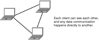
The ad-hoc WLAN network is an unplanned, unmanaged peer-to-peer relationship. All nodes are equivalents and can directly communicate with other nodes in their vicinity. They do not need to pass through a central point of control. An ad-hoc network thus forms a fully meshed network that uses radio as the interconnection system.
The network is a logical mesh. As mentioned earlier, WLANs physically adopt a bus topology with the ether forming the backbone. This mesh should be thought of as a logical communications overlay. Figure 1-8 illustrates this any-toany relationship. The dotted lines depict the virtual interconnections that are created by means of radio links.
Even though ad-hoc networks are created on the fly and adopt an any-to-any scheme, they still must share a minimum set of common parameters such as the radio frequency, a common identifier setting, and (if used) a common encryption method.
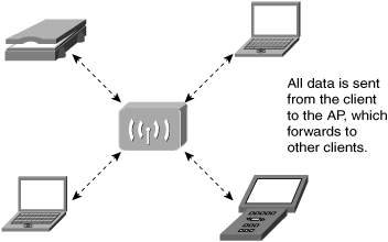
Infrastructure mode is the most common network type used today for enterprise solutions. Fundamentally, this WLAN mode adopts a client/server model. The “clients” are devices with a WLAN interface such as PCs, Personal Digital Assistants (PDAs), wireless IP phones, and many others. The “server” in this case is the AP. Figure 1-9 illustrates the AP – client relationship.
The logical topology versus physical topology differentiation is the same for ad-hoc mode as for infrastructure mode. Even though Figure 1-9 would lead you to believe that in infrastructure mode, WLAN adopts a star topology, it is in reality a physically collapsed bus topology. This is because the RF medium forms a single Layer 2 collision domain. You can consider it to be equivalent to a traditional coaxial Ethernet network where the electrical wire has been replaced by radio waves. In the perfect environment, every station hears every transmission from every other station.
Because both Ethernet (802.3) and WLAN (802.11) use a bus topology, it is not surprising that they use the same technique for determining accessibility to the physical medium. The method employed by these types of networks is carrier sense multiple access (CSMA). There are, however, some subtle differences to medium access control with regard to collision handling because of the RF medium.
Collisions occur when two stations inadvertently believe that the medium is available and both start transmitting at the same time. When frames collide, data is lost. Neither frame is successfully received and an orderly retransmit is required. Because there is no supervisory point of control, stations must make up for this by using their own intelligence to secure the medium. Essentially, every station effectively becomes its own traffic cop to manage the orderly access to the physical medium.
APs in infrastructure mode form the gateway for the client to the rest of the network. Indeed, all communications must pass through the AP. As such, logical groups of stations are created that share a gateway. This gateway or AP defines a standalone WLAN cell.
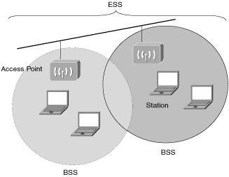
In infrastructure mode, WLANs are comprised of cells. The technical name for a WLAN cell is Basic Service Set (BSS) and has a distinctive identifier known as a Service Set Identifier (SSID). The SSID is the common denominator that logically identifies WLAN cells. It effectively segments the ether through the creation of a virtual Layer 2 network.
The WLAN cells can be extended or virtually combined when several BSS cells are in proximity of each other. This is known as an Extended Service Set (ESS). The ESS extends the virtual Layer 2 network by combining multiple BSSs into a singular larger network. Figure 1-10 shows the segmentation into the logical groups of stations that form BSSs. It also illustrates the combination of multiple BSSs that forms an ESS.
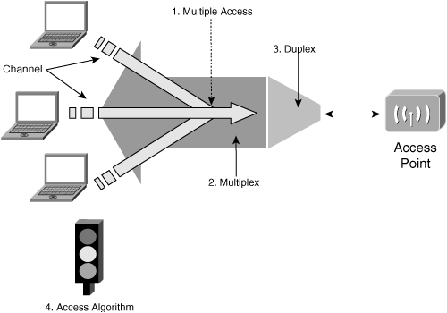
When reviewing the basic setup of a WLAN, several challenges need to be resolved. These include the following:
How multiple terminals share the air channel (multiple access technology)
How transmitting stations merge data (multiplexing)
How to share between up- and down-link (duplexing)
How access to the medium is controlled (access algorithm)
To obtain a better grasp of the meaning of these various technologies, the analogy of individuals using cars to ship goods through a one-way tunnel is useful:
Multiple access determines how the cars form a sequence.
Multiplexing defines how the goods are loaded into the cars.
Duplexing is resolving the problem of two-way traffic through a one-way tunnel.
The access algorithm determines when it is safe for a car to enter the tunnel.
Figure 1-11 illustrates the relationship between the technologies and where they are relevant within a WLAN.
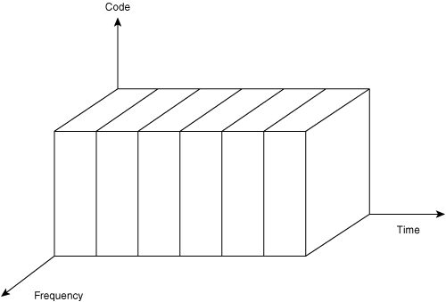
In the context of communications technologies, information can be distributed in both space and time. You can multiplex information using coding, frequency, or time. The respective access methods are as follows:
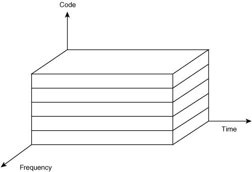
Code division multiple access (CDMA)—. In CDMA, the data is sliced into the encoding of the signal. In this method, time and frequency stay constant. Figure 1-12 shows an example of a CDMA network.
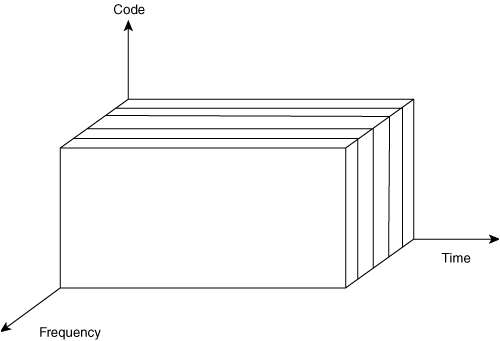
Frequency division multiple access (FDMA)—. FDMA is the method of slicing data into separate frequencies. In this case, time and coding are constant. Figure 1-13 shows an FDMA network.
Time division multiple access (TDMA)—. TDMA slices data into separate slices of time, where frequency and coding are constant. Figure 1-14 shows a TDMA network.
Transmitting stations use multiplex technology to merge data onto the air channel. Similar to access technology, multiplexing can be done along code, frequency, and time dimensions.
In the case of WLAN technologies, an RF signal is sent using one of three modulation types:
Frequency Hopping Spread Spectrum (FHSS)
Direct Sequence Spread Spectrum (DSSS)
Orthogonal Frequency Division Multiplexing (OFDM)
FHSS is an obsolete technology and is not employed in any of today’s WLAN implementations. As such, we will look at DSSS and OFDM only.
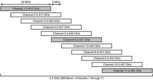
DSSS is an older and simpler to implement—and hence more economical, method for RF modulation. Signals are transmitted on a low-amplitude carrier wave (RF) across a wide band. This is done to combat interference. DSSS defines a channel-to-channel separation of 5 MHz. However, each channel is 22 MHz in width (11 MHz to the left and 11 MHz to the right). Because of this spreading, channels overlap into each other, which inherently causes channel-to-channel interference.
There are only three channels in DSSS multiplexing that do not overlap with each other. These are referred to as the transmit or non-overlapping channels and consist of channels 1, 6, and 11.
Figure 1-15 represents the 2.4 GHz Industrial, Scientific and Medical (ISM) band. Both IEEE 802.11b and IEEE 802.11g operate in this band, specifically between 2.4 GHz and 2.4835 GHz.
OFDM is more complex to implement because it uses narrow and precise RF waves. At 20 MHz, the OFDM channel-to-channel separation is wider than that of DSSS modulation at 5-MHz separation. This precise and focused channel spacing is key to the improved data rates that are possible with OFDM multiplexing. To obtain an even higher data rate, each of the eight transmit channels is further divided into 52 subchannels. As a result, there is more surface area to encode data.
Figure 1-16 shows the 5-GHz Unlicensed National Information Infrastructure (UNII) band. 802.11a operates in this band, specifically those frequencies between 5.15 GHz and 5.350 GHz.
Duplex technology is used to share the same space for an uplink and downlink. Two kinds of duplex technology are relevant to WLANs:
Access technology defines which WLAN node can take control of the RF spectrum and how. Although similar to the access method in other IEEE 802 standards, WLANs employ carrier sense multiple access/collision avoidance (CSMA/CA) technology. The defining feature in WLAN is collision avoidance. WLANs use open air, which is borderless, as opposed to other IEEE 802 forms where the transport medium is bounded. In WLANs, detecting whether the medium is busy is nearly impossible. Stations must counter this problem by utilizing acknowledgements to determine when the medium is in use before transmitting their data—hence the name collision avoidance.
This section describes the role and framework of WLAN radio frequencies. WLANs have two specific slices of the RF spectrum: 2.4 GHz and 5 GHz. These frequency bands are unlicensed bands that can be used freely without registration or financial obligation.
With their increasing popularity, the use of vast amounts of WLAN devices in these bands has changed access to the airspace from free into a free-for-all. Because the spectrum is unregulated, the possibility of an excessive number of devices in each other’s vicinity exists. Indeed, the compounding of the RF interference problem in combination with the massive contention for access to the ether can saturate the frequency range to a point where no successful communication is possible. In this case, the system simply “collapses.” This adverse situation must therefore be preempted and addressed.
Various characteristics that are specific to a WLAN can influence the actual throughput that can be achieved. These elements include the modulation technique used, the power of the radio signal, and environmental effects such as attenuation and multipath effects. Each will now be discussed in more detail.
Modulation is the process of overlaying a content signal on a carrier signal. The overlaying can be done in terms of amplitude, frequency, or phase. Generally there are three forms of digital modulation:
As a rule, the more complex the algorithm, the higher the data rate.
In a perfect environment, the distance that an RF wave will travel is dependent on its frequency and amplitude. However, in a real-world deployment, physical variables such as walls and people have a further impact on path loss. This path loss includes the following:
Transmitter power—. The amount of power that the station uses to transmit a signal.
Transmitter and receiver antenna gain—. A measurement in the increase of the radio signal, measured as dB or dBi.
Transmitter and receiver cable losses—. The loss of signal strength (attenuation) that occurs as a signal passes through a length of copper cable or connector.
Receiver sensitivity—. The amount of signal loss as a result of the receiver being able to interpret a signal, measured in dBi.
Noise and interference—. Other RF signals that exist in the area of an AP or Client and that adversely influence the original signal.
Note
The decibel (dB) is not a unit in the sense that a meter or an ampere is. Feet and amperes are defined quantities of distance and electrical current. A decibel is a relationship between two values of power. A decibel (dB) is defined as follows:

A decibel intends to facilitate the comparison of power levels that are orders of magnitude different. In the context of radio signals, the decibel typically represents a signal-to-noise ratio.
Power and antenna gain have the most direct effect on signal amplitude. Within the standards for each protocol, as governed by regional regulatory bodies, there are defined limits on the transmit power and antenna use. These limitations directly influence the maximum reach of WLANs.
Generally speaking, antenna gain is measured in dBi (isotropic), which is based on a “theoretical antenna.” This provides a constant baseline.
Another important aspect in WLANs is the environment and how it affects radio waves. Because a myriad of environmental elements influence a radio wave, the wave’s actual behavior is exceedingly hard to predict deterministically. For example, RF absorption by objects reduces the strength of the signal. In a crowded office, radio transmissions are dampened as they pass through walls, desks, and even people. This is not the case in an open warehouse. Similarly, a functioning microwave oven emits radio waves that might interfere with WLAN signals, especially when in close proximity to any WLAN device.
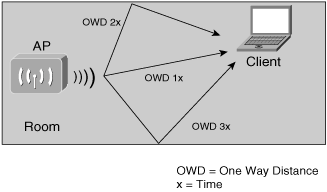
Radio waves have no boundaries and “bounce” around. This causes an effect known as multipath. The reflection of waves causes them to be received not only multiple times by stations but also at different intervals. Radio receivers need to be able to extract the correct signal from these disparate ones and ferret out the good from the bad.
Figure 1-17 illustrates how the ricochet effect of radio waves off objects leads to the multipath effect. Several signals with the same data are sent from the AP into free space, which then “ricochet” in many different directions off different walls (boundaries). The client receives each signal at different times.
WLAN device manufacturers integrate specific components into their products to deal with multipath. This is implemented in both hardware and software.
Special or customized antennas can also be used to combat the adverse effect of multipath. Directional antennas focus signals and hence counteract the general effects of multipath. Additionally, the radio receiver can accomodate for multipath by reacting to “delay spread” and rejecting duplication of already received signals.
All the negative impacts discussed thus far have a direct influence on the relative throughput of a WLAN. For a WLAN to be able to send data, it must accommodate changes incurred from these detrimental factors.
To effectively cope with all the adverse external effects, WLANs have adopted a self-throttling throughput strategy. As the strength and quality of a signal diminishes, a WLAN will automatically gear down to adjust to a lower throughput rate. The opposite is also true. As the signal’s quality increases, the data rate rises.
What we have alluded to is that the defined data rates for each standard actually represent a nominal theoretical boundary. In a perfect scenario, these nominal maxima could be met. However, the reality is that interference, internal radio signaling, antenna type, atmospheric conditions, noise, attenuation, and other influences have a role in determining the real throughput. Actual usable throughput is generally about half of the theoretical rates. For example, in an 802.11b network, the theoretical data rate of 11 Mbps is reduced to an actual usable rate of around 6 Mbps. The same effect of stated to actual data rates applies to 802.11g and 802.11a.
No magic formula enables the actual throughput to be predetermined because the factors that influence the real throughput are many and diverse.
As you have learned, the radio spectrum is at the heart of any wireless network. Because RF devices are used in many critical day-to-day applications, they have become heavily regulated. Police, fire, and air traffic control systems use RF in some form. The regulations are in place to ensure that communications can coexist and occur in a deterministic and orderly fashion. For example, the police can be notified of a bank robbery and airplanes can communicate consistently with air traffic control.
Regulations surrounding RF are managed by both national and regional bodies. Significant disparities can exist between respective local regulations. Awareness of potential differences in RF regulations is the first step to complying with them. The second step is knowing which regulatory bodies are relevant in your specific case and where to consult upon them.
A sample of the most important regulatory bodies includes
U.S. Federal Communication Commission (FCC)
European Telecommunications Standards Institute (ETSI)
Industry Canada (IC)
China Wireless Telecommunication Standard group (CWTS)
Japan’s Telecom Engineering Center (TELEC)
Note
Note that this list is far from exhaustive. Contact your local government to assist you in identifying your appropriate regulatory bodies.
Each regulatory body defines the specific use or constraint on the use of ISM and UNII radio frequencies. Local authorities define which parts of the spectrum are permitted for use, the power levels that can be emitted by the radio, and allowances surrounding approved commercial and consumer use.
Vendors of WLAN devices almost always consider local regulations when developing products. However, WLAN equipment that is compliant for one region does not implicitly translate into compliance for other regions. As such, geographical portability of the WLAN devices is not guaranteed from a regulatory point of view. When planning a WLAN deployment across multiple countries, ensure that the selected equipment has been approved for each location.
Additional concerns related to RF are the open availability of the unlicensed bands and their potential overuse. Because these frequency ranges are unlicensed, many devices can coexist and potentially compound interference problems.
The IEEE 802.11 WLAN standard contains a number of subsets that can potentially lead to confusion. Indeed, the 802.11 substandards have resulted in the creation of an alphabet soup. This section brings order to this situation and expands upon some of the more subtle differences between the various WLAN standards. The IEEE standards that are covered are 802.11b, 802.11g, and 802.11a.
Because the respective standards were developed and ratified at different points in time, WLAN equipment manufacturers have also produced hybrid devices that are capable of spanning multiple standards. These are the so-called dual-band devices.
IEEE 802.11b is the most commonly known WLAN standard. At the time of writing of this book, 802.11b WLANs enjoy the highest market adoption. The standard has three main characteristics:
DSSS is used for modulation.
The frequency range is 2.4 GHz.
The maximum data rate is 11 Mbps, although the actual throughput is 5 to 6 Mbps.
Because DSSS is a simpler technology to implement in silicon—as opposed to software—it greatly accelerated the 802.11b technology’s time to market. However, the simplicity of implementation comes at the cost of efficiency. Early deployments of WLANs were small and primarily used as secondary means for network connectivity. In such an environment, the maximum bandwidth of 11 Mbps was all that was needed, and it served these networks well.
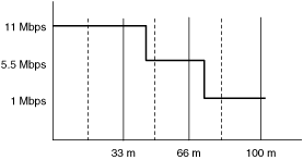
The four respective data rates that are employed by 802.11b are 1 Mbps, 2 Mbps, 5.5 Mbps, and 11 Mbps. The effective range goes from 0 to 100 meters. The relationship between nominal throughput and transmission distance is illustrated in Figure 1-18.
IEEE 802.11g is a hybrid implementation of WLAN technology. The following are its key characteristics:
Both DSSS and OFDM are used for modulation in function of the desired data rate.
The frequency range is 2.4 GHz.
The maximum data rate is 54 Mbps.
The higher data rate and backward compatibility with 802.11b are making IEEE 802.11g the protocol of choice to displace 802.11b. 802.11g operates in the 2.4-GHz frequency range and can employ DSSS, thus facilitating backward compatibility with 802.11b in the lower throughput range. However, 802.11g employs OFDM for data rates above 11 Mbps as opposed to DSSs for data rates below 11 Mbps. OFDM is more efficient than DSSS but also more complex to implement, hence the later time to market and higher initial pricing for 802.11g.
Note
The frequency band alone does not guarantee compatibility with 802.11b. Other components such as the same modulation and multiplexing techniques are also required for compatibility. For example, 802.11g makes use of DSSS when operating at speeds up to 11 Mbps and switches to OFDM for higher data rates.
Every benefit has a consequence, and the same is true for the backward compatibility of 802.11g with 802.11b. A mixed environment results in lower effective data rates for 802.11g because the different multiplexing methods impact the timing of the data transmission and reception. 802.11b packets are sent out with longer interval times as opposed to 802.11g stations. As a result, 802.11g stations throttle down by extending their transmit wait timers so that they do not drown out 802.11b stations.
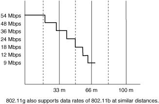
Just like 802.11b, 802.11g is limited by power output constraints, governed by local or regional governments. However, the tighter timing of OFDM enables data rates of up to 54 Mbps in the same frequency band and power level. The 12 respective data rates that are employed by 802.11g are 1 Mbps, 2 Mbps, 5.5 Mbps, 6 Mbps, 9 Mbps, 11 Mbps, 12 Mbps, 18 Mbps, 24 Mbps, 36 Mbps, 48 Mbps, and 54 Mbps. The effective range goes from 0 to 100 meters. The relationship between nominal throughput and transmission distance is illustrated in Figure 1-19.
Contrary to common belief, the IEEE 802.11a standard is not new to WLAN space, having been ratified in 1999. The three key characteristics of 802.11a are as follows:
OFDM is used for modulation.
The frequency band is 5 GHz.
The maximum data rate is 54 Mbps.
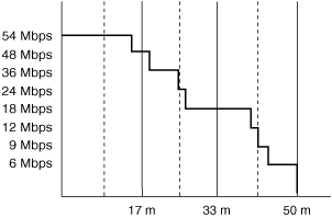
Another important aspect of 802.11a is that it has eight non-overlapping channels to transmit on, as opposed to the three in 802.11b/g. This higher number of transmit channels allows for more active sessions. Indeed, the increased number of channels allows more stations to transmit in a given space. This is basically equivalent to adding lanes to a highway. The relationship between nominal throughput and transmission distance for 802.11a is illustrated in Figure 1-20.
The drawback to working in the 5-GHz range is that the radios are more sensitive to environmental conditions. 802.11a has had initial barriers to overcome, namely with price and performance, which probably explain the lower adoption rates. Finally, when you consider that the new 802.11g standard offers comparable speeds and has the significant added benefit of backwards compatibility with 802.11b, it is not surprising that 802.11a faces this higher barrier to entry.
Table 1-2 provides a brief summary of the key differences between 802.11a, 802.11b, and 802.11g.
802.11a uses a completely different frequency range from 802.11b and 802.11g. If you install 802.11a APs, you must ensure that you have 802.11a clients. In most cases, both infrastructure providers and client radio manufacturers build multiradio products.
Both 802.11a and 802.11h use the 5-GHz range and are designed to coexist. 802.11h complements 802.11a so that stations in this band can operate worldwide. If you have an 802.11a network, you don’t need 802.11h. Conversely, if you have an 802.11h network, you already have 802.11a without performance or quality issues.
You have examined the three LAN standards that define WLANs. However, as the requirements for interoperability, support for regional regulatory requirements, improved security, and other enhancements have evolved, the original IEEE 802.11 working groups have been extended. Many new standards have been defined or are currently under development. This is the cause of much additional confusion. Not only do you need to be familiar with the three WLAN standards (802.11b, 802.11a, and 802.11g), but you also need to deal with an additional raft of new standards. Indeed, more letters have been added to the alphabet soup.
It is important to note that the 802.11 standards are constantly evolving. Because the IEEE works through discussion and democratic voting, the process of ratifying a new standard can be lengthy. Many of the current 802.11 standards are therefore still under development. However, this does not stop eager manufacturers from sometimes releasing products that are in a “preratification” state as an attempt to beat their competitors to market. 802.11g is a prime example. Many 802.11g products were released before the standard was put to vote. For the most part, manufacturers will develop their products with the intention of embracing the ratified standard later on. Nevertheless, there are those who will use their current product as a stepping stone for the next standard. We go into further detail in Appendix A, “Wireless LAN Standards Reference.”
This chapter introduced the value of mobility in today’s information-driven society. The desire for access to information anywhere and anytime has been and will continue to be a key driver for wireless communications technologies in both the business and personal arena. This chapter provided a structured approach to understanding WLANs from a technological point of view by introducing the OSI framework. The framework not only helps you understand how WLANs position themselves next to other internetworking technologies, but also aids the introduction of key technical aspects that are specific to WLANs. Key components such as multiaccess, multiplex, duplex, and access technologies were touched upon. In addition, the impact of internal and environmental effects such as power, attenuation, distortion, and noise on actual WLAN throughputs was discussed. Finally, this chapter untangled the IEEE 802.11 alphabet soup by providing a high-level overview of the main substandards and their respective differences.

