
5
Batteries and Power
Everything that you make or adapt is going to need to get its power from somewhere. This might be from a household electricity adapter, solar panels, rechargeable batteries of various sorts, or just standard AA batteries.
In this chapter, you will find out all about batteries and power, starting with batteries.
 |
I use the word “battery” to describe both batteries and cells. Strictly speaking, a battery is a collection of cells wired one after the other to give the desired voltage. |
Selecting the Right Battery
There are many types of battery on the market. So, to simplify things, in this chapter we will just look at the most common types of battery, those that are readily available and that will be used in most of the devices in this book.
Battery Capacity
Whether single-use or rechargeable, batteries have a capacity—that is, they hold a certain amount of electricity. Manufacturers of single-use batteries often don’t specify this capacity in the batteries you buy from a supermarket. They just label them heavy duty / light duty, and so on. This is a little like having to buy milk and being given the choice of “big bottle” or “small bottle” without being able to see how big the bottle is or be told how many pints or liters it contains. One can speculate as to the reasons for this. One reason might be that battery producers think the public isn’t intelligent enough to understand a stated battery capacity. Another might be that the longer a battery is on the shelf, the more its capacity shrinks. Still another is that the capacity actually varies a lot with the current drawn from the battery.
Anyway, if a battery manufacturer is kind enough to tell you what you are buying, the capacity figure will be stated in Ah or mAh. So a battery that claims to have a capacity of 3000mAh (typical of a single-use alkaline AA cell) can supply 3000mA for one hour. Or, alternatively, 3A for an hour. But it doesn’t have to draw 3A. If your project only uses 30mA, you can expect the battery to last 100 hours (3000/30). In truth, the relationship is not quite that simple, because as you draw more current, the capacity decreases. Nevertheless, this will do as a rule of thumb.
Maximum Discharge Rate
You cannot take a tiny battery like a CR2032 with a capacity of 200mAh and expect to power a big electric motor at 20A for 1/100 of an hour (six minutes). There are two reasons for this. First, all batteries actually have an internal resistance. So, it is as if there is a resistor connected to one of the terminals. This varies depending on the current being drawn from the battery, but may be as high as a few tens of ohms. This will naturally limit the current.
Second, when a battery is discharged too quickly, by too high a current, it gets hot—sometimes very hot, sometimes “on fire” hot. This will damage the battery.
Batteries therefore also have a safe discharge rate, which is the maximum current you can safely draw from it.
Single-Use Batteries
Although somewhat wasteful, sometimes it makes sense to use single-use batteries that cannot be recharged. You should consider single-use batteries if:
• The project uses very little power, so they will last a long time anyway.
• The project will never be close to someplace where it can be charged up.
Table 5-1 shows some common single-use batteries. These figures are typical values and will vary a lot between actual devices.
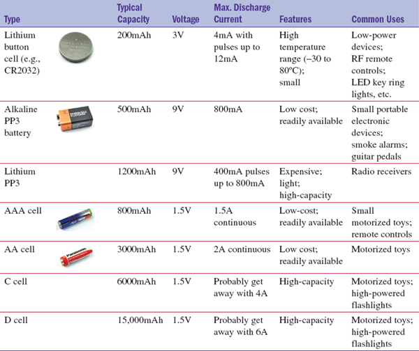
TABLE 5-1 Single-Use Battery Types
Especially when it comes to the maximum discharge rate, you may get away with a lot more, or the battery may fail or get very hot with considerably less. It will also depend on how well ventilated a box they are in, as heating under high currents is a big problem.
So in the spirit of hacking electronics, spend less time planning and more time trying. See how hot it gets and how long it lasts. After all, we are having fun here, not designing a product.
| |
Some of the photographs in the table are of branded batteries. The figures shown are for batteries of that type, not specifically the batteries listed. |
Roll Your Own Battery
A single-cell battery with a voltage of just 1.5V is probably not going to be of any use. You will normally need to put a number of these cells in series (end to end) to produce a battery of the desired voltage.
When you do this, you do not increase the capacity. If each cell was 2000mAh, then if you put four 1.5V batteries in series, the capacity would still be 2000mAh, but at 6V rather than 1.5V.
Battery holders such as the one shown in Figure 5-1 are a great way of doing this. Look closely at how the battery holder is constructed and you’ll notice how the positive of one battery is connected to the negative of the next, and so on.
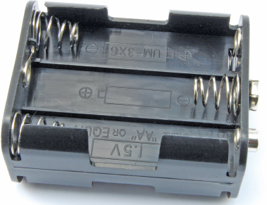
FIGURE 5-1 A battery holder
This holder is designed to take six AA batteries so as to produce an overall voltage of 9V. Battery holders like this are available to take two, four, six, eight, or ten cells, both in AA and AAA.
Another advantage of using a battery holder is that you can use rechargeable batteries instead of single-use batteries. However, rechargeable cells normally have a lower voltage, so you have to take this into account when calculating the overall voltage of your battery pack.
Selecting a Battery
Table 5-2 should help you decide on a suitable battery for your project. There is not always a best answer to the question “Which battery should I use?” and this table is definitely in the territory of rules of thumb.
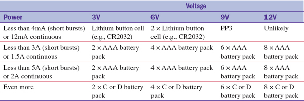
TABLE 5-2 Selecting a Single-Use Battery
You should also do the math and include how frequently the battery will need replacing.
Rechargeable Batteries
Rechargeable batteries can provide both cost and green benefits over single-use batteries. They are available in different types and in different capacities. Some, such as rechargeable AA or AAA batteries, are designed as replacements for single-use batteries, and you remove them to charge in a separate charger. Other batteries are intended to be built into your project so all you have to do is plug a power adapter into your project to charge the batteries without removing them. The advent of cheap, high-capacity, low-weight lithium polymer (LiPo) batteries has made this a common approach for many items of consumer electronics.
Table 5-3 shows some commonly used types of rechargeable batteries.
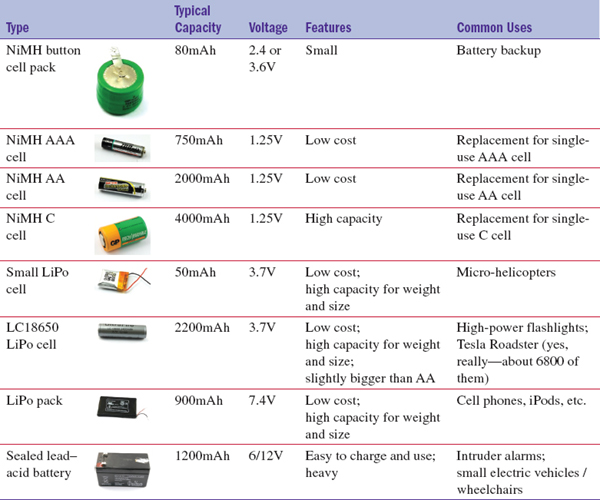
TABLE 5-3 Rechargeable Batteries
Although there are many more types than this, these are the most commonly used batteries. Each type of battery has its own needs when it comes to charging, and we will look at each in later sections.
Table 5-4 summarizes the features of NiMH, LiPo, and lead–acid battery technologies.
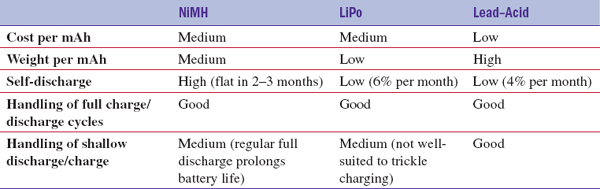
TABLE 5-4 Characteristics of Different Battery Technologies
If you want your project to charge a battery in place, then a LiPo or sealed lead–acid battery is probably the best choice. However, if you want the option to remove the battery and/ or use single-use batteries, then a AA battery pack is a good compromise between capacity and size.
For ultra-high-power projects, lead–acid batteries, despite being an ancient technology, still perform pretty well, just as long as you don’t have to carry them around! They are also easy to charge and are the most robust of the technologies, offering the least chance of fire or explosion.
Charging Batteries (in General)
Certain principals apply no matter what kind of battery you are charging. So read this section before reading those that follow it concerning specific battery types.
C
The letter C is used to denote the capacity of a battery in Ah or mAh. So, when people talk about charging a battery, they often talk about charging at 0.1C or C/10. Charging a battery at 0.1C means charging it at 1/10 of its capacity per hour. For example, if a battery has a capacity of 2000mAh, then charging it at 0.1C means charging it with a constant current of 200mA.
Over-Charging
Most batteries do not respond well to being over-charged. If you keep supplying them with a high charging current, you will damage them. They often also get hot. In the case of LiPo batteries, this can be “hot” in a fiery sort of way.
For this reason, chargers often charge at a low rate (called trickle charging), so that the low current will not damage the battery. Clearly this makes charging slow. Or, they will use a timer or other circuitry to detect when a battery is full and either stop charging altogether, or switch to trickle charging, which keeps the battery topped up until you are ready to use it.
With some kinds of battery, notably LiPos and the lead–acid variety, if you charge the battery with a constant voltage, then as the battery becomes charged, its voltage rises to match the charging voltage and the current naturally levels off.
Many LiPo batteries now come with a little built-in chip that prevents over-charging automatically. Always look for batteries with such protection.
Over-Discharging
You are probably starting to get the impression that rechargeable batteries are fussy. If so, you’re right. Most types of battery are equally unhappy if you over-discharge them and let them go completely flat.
Battery Life
Anyone with a laptop more than a few years old will notice that the capacity of the battery gradually decreases until the laptop only works when plugged in, since the battery has become completely useless. Rechargeable batteries (whatever the technology) can only be recharged a few hundred (perhaps 500) times before needing to be replaced.
Many manufacturers of consumer electronics now build the battery into the device in such a way that it is not “user serviceable,” with the rationale that the life of the battery is probably longer than the attention span of the consumer.
How to Charge a NiMH Battery
If you are going to remove your batteries to charge them, this section is pretty trivial. You take them out and put them in a commercial NiMH battery charger that will charge them until they are full and then stop. You can then put them back into your project and you are done.
If, on the other hand, you want to leave the batteries in place while you charge them, then you need to understand a little more about the best way to charge your NiMH batteries.
Simple Charging
The easiest way to charge a NiMH battery pack is to trickle charge it, limiting the current with a resistor. Figure 5-2 shows the schematic for charging a battery pack of four NiMH batteries using a 12V DC adaptor like the one we used back in Chapter 1 to make our fume extractor.
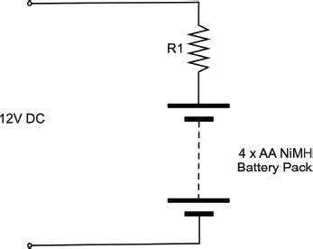
FIGURE 5-2 Schematic for trickle charging a NiMH battery pack
To calculate the value of R1, we first have to decide what current we want to charge our battery with. Generally, a NiMH battery can be safely trickle charged with less than 0.1C indefinitely. If the AA batteries we have each hold a C of 2000mAh, then we can charge them at up to 200mA. To be on the safe side, and if we planned to allow the batteries to “trickle” charge most of the time—for, say, a battery backup project—I would probably use a lower current of 0.05C or more conveniently C/20, which is 100mA.
Typically, the charge time for NiMH batteries is about 3C times the charging current, so at 100mA, we could expect our batteries to take 3 × 2000mAh / 100mA = 60 hours.
Back to calculating R1. When the batteries are discharged, each will be at a voltage of about 1.0V, so the voltage across the resistor will be 12V – 4V = 8V.
Using Ohm’s law, R = V / I = 8V / 0.1A = 80Ω.
Let’s be conservative and choose the convenient resistor value of 100Ω. Feeding this back in, the actual current will be I = V / R = 8V / 100Ω = 80mA.
When the batteries are fully charged, their voltage will rise to about 1.3V so the current will reduce to: I = V / R = (12V – 1.3V × 4) / 100Ω = 68mA.
That all sounds just fine, our 100Ω will be great. Now we just need to find out what maximum power rating we need for R1.
P = I V = 0.08A × 8 = 0.64W = 640 mW
So, we should probably use a 1-W resistor.
Fast Charging
If you want to charge the batteries faster than that, then it is probably best to use a commercial charger, which will monitor the batteries and turn itself off or reduce the charge to a trickle when the batteries are full.
How to Charge a Sealed Lead–Acid Battery
These batteries are the least delicate of the battery types and could easily be trickle charged using the same approach as for NiMH batteries.
Charging with a Variable Power Supply
However, if you want to charge them faster, then it is best to charge them with a fixed voltage, with some current limiting (a resistor again). For a 12V battery (halve this for a 6V battery) until a discharged battery gets to around 14.4V, you can charge it with almost as much current as your power supply can take. It’s only when it gets to this voltage that you need to slow down the charging to a trickle to prevent the battery from getting hot.
The reason we need to limit the current when the battery first starts to charge is that even if the battery doesn’t get hot, the wires to it might get hot and whatever is supplying the voltage will only be able to supply a certain amount of current.
Figure 5-3 shows an adjustable power supply. Once you get into electronics, this is one of the first pieces of test equipment you should buy. You can use it in place of batteries while you are working on a project, and also use it to charge up pretty much any type of rechargeable battery.
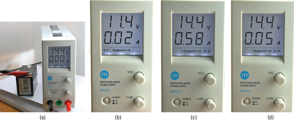
FIGURE 5-3 Using a variable power supply to charge a lead– acid battery
A variable power supply lets you set both an output voltage and a maximum current. So the power supply will try and supply the specified voltage until the current limit is reached, at which point, the voltage will drop until the current falls back below the set current.
Figure 5-3a shows the power supply set to 14.4V and we have attached the power leads to an empty 12V 1.3Ah sealed lead–acid battery. We will start by adjusting the current setting of the power supply to minimum, so as to prevent any nasty surprises. The voltage immediately drops to 11.4V (Figure 5-3b), so we can gradually increase the maximum current. In actual fact, even with no current limiting (turning the current knob to maximum), the current only rose to 580mA and the voltage increases to 14.4V (Figure 5-3c). After about two hours, the current has dropped to just 200mA, indicating that our battery is getting full. Finally, after four hours, the current is just 50mA and the battery is now fully charged (Figure 5-3d).
How to Charge a LiPo Battery
The technique we have just used on a lead–acid battery using a variable power supply will work just as well on a LiPo battery if we adjust the voltage and current accordingly.
For a LiPo cell, the voltage should be set to 4.2V and the current limited (usually to 0.5A) for a smallish cell, but currents up to C are sometimes used in radio-controlled vehicles.
However, unlike lead–acid and NiMH batteries, you cannot put a number of cells in series and charge the whole lot as one battery. Instead, you have to charge them separately, or use a “balanced charger” that monitors the voltage at each cell separately and controls the power to each.
The safest and most reliable way to charge a LiPo is to use one of the chips that exist just for that purpose. These chips are cheap, but generally only available as surface-mounted components. However, there are plenty of ready-made modules available, many of which use the MCP73831 IC. Figure 5-4 shows two of these—one from SparkFun (see the Appendix, M16) and one for just a few dollars from eBay.
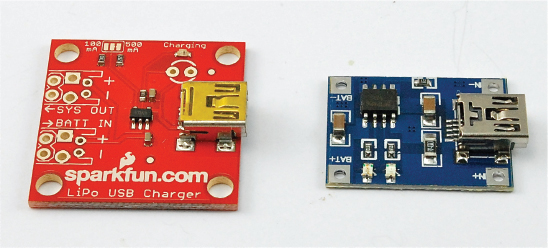
FIGURE 5-4 SparkFun and generic LiPo chargers
Both are used in the same manner. They will charge a single LiPo cell (3.7V) from a USB input of 5V. The SparkFun board has space on the PCB for two other connectors, one to which the battery is connected and the other for a second connection to the battery—the intention is that you connect the electronics that will use the battery to the second socket. The sockets can be either JST connectors as are often found on the end of the leads of a LiPo batter, or just screw terminals. The SparkFun module allows you to select the charging current, using a connection pad.
The generic module on the right has a fixed charge rate of 500mA and just a single pair of connections for the battery.
It is not a good idea to trickle charge a LiPo. If you want to keep them topped up, for say a battery backup solution, then leave them attached to the charger.
Hacking a Cell Phone Battery
Most of us have a cell phone or two languishing in a drawer somewhere, and one of the useful components that can usually be scavenged (assuming it’s not the reason the phone is in the drawer) is the battery. The power supply is another useful item.
Figure 5-5a shows a fairly typical vintage cell phone battery. The battery is 3.7V (a single cell) and is 1600mAh (pretty good). Cell phone batteries normally have more than just the usual two connections for positive and negative. So the first task must be to identify the connections on the battery.
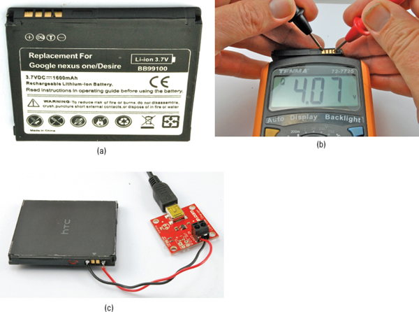
FIGURE 5-5 Hacking a cell phone battery
To identify the positive and negative connections to the cell, just put your multimeter into the 20V DC range and test each combination of pairs until you get the meter to read something over 3.5V, depending on how well charged the battery is (Figure 5-5b).
The batteries often have gold-plated contacts that make them very easy to solder leads to. Once they have leads attached, you can use a charger like the one described in the previous section. Figure 5-5c shows the SparkFun charger module being used for just that purpose.
 |
When using a LiPo battery, remember that if you discharge them too far (below about 3V per cell), you can permanently damage them. Most new LiPo batteries will include an automatic cut-off circuit, built into the battery package, to prevent over-discharging, but this may not be the case for a scavenged battery. |
Controlling the Voltage from a Battery
The thing with batteries is that even though they may say 1.5V, 3.7V, or 9V on the package, their voltage will drop as they discharge—often by quite a high percentage.
For example, a 1.5V alkaline AA battery when brand new will be about 1.5V and will quickly fall to about 1.3V under load but still deliver useful amounts of power down to about 1V. This means that in a pack of four AA batteries, the voltage could be anything between 6V and 4V. Most types of battery, whether single-use or rechargeable, exhibit a similar voltage drop.
This may not matter much; it just depends on what the battery is powering. If it is powering a motor or an LED, then the motor will just go a bit more slowly, or the LED will be a little dimmer as the battery discharges. However, some ICs have a very narrow voltage tolerance. There are ICs designed to work at 3.3V that specify a maximum working voltage of 3.6V. Similarly, if the voltage drops too low, the device will also stop working.
In fact, many digital chips such as microcontrollers are designed to work at a standard voltage of 3.3V or 5V.
To ensure a steady voltage, we need to use something called a voltage regulator. Fortunately for us, voltage regulators come as convenient three-pin, low-cost chips that are very easy to use. In fact, the packages just look like transistors, and the bigger the package, the more current they can control.
Figure 5-6 shows how you would use the most common of voltage regulators, called the 7805.
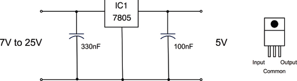
FIGURE 5-6 A voltage regulator schematic
Using just a voltage regulator IC and two capacitors, any input voltage between 7V and 25V can be regulated to a constant 5V. The capacitors provide little reservoirs of charge that keep the regulator IC operating in a stable manner.
In the following experiment with a 7805, we will omit the capacitors, as the supply voltage is a steady 9V battery and the load on the output is just a resistor (Figure 5-7).
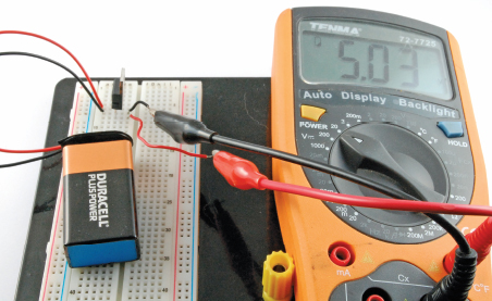
FIGURE 5-7 Experimenting with the 7805
The capacitors become much more necessary when the load varies (in other words, in the amount of current that it draws), something that is true of most circuits.
You Will Need
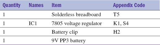
Wire up the breadboard as shown in Figure 5-8.
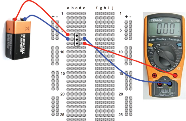
FIGURE 5-8 The 7805 breadboard layout
Breadboard
With the battery connected, the multimeter should display a voltage of close to 5V.
Although 5V is a very common voltage, there are voltage regulators for most common voltages, as well as the LM317 voltage regulator that we discussed in Chapter 4, that as well as providing constant current, can also be configured as a voltage regulator.
Table 5-5 lists some common voltage regulators that provide different output voltages and different current handling capabilities.
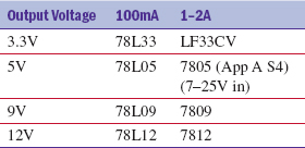
TABLE 5-5 Voltage Regulators
Boosting Voltage
The voltage regulator ICs in the section titled “Controlling the Voltage from a Battery” only work if the input voltage is greater than the output voltage. In fact, it normally has to be a couple of volts higher, but some more expensive voltage regulators called LDO (low drop out) regulators are available that only require about half a volt more on the input than the output.
Sometimes, however—and cellular phones are a good example of this—it is very convenient to use a single-cell LiPo battery of 3.7V when we require a higher voltage (often 5V) for the circuit.
In these situations, you can employ a very useful circuit called a buck-boost converter. These use an IC and a small inductor (coil of wire) and by applying pulses to the inductor, produce a higher voltage. Actually, it’s more complex than that, but you get the idea.
Buck-boost converters are readily available as modules on well-known auction sites. You can find 1A adjustable modules that will provide an adjustable output of 5V to 25V from 3.7V for a few dollars. Try searching for “Boost Step-Up 3.7V.” The main module suppliers also provide such boards for around USD 5.
SparkFun sells an interesting module (see the Appendix, M17) that combines a LiPo battery charger with a buck-boost, so you can both charge your LiPo from an external USB 5V input and use the 3.7V LiPo cell to provide an output of 5V using the buck-boost (Figure 5-9).
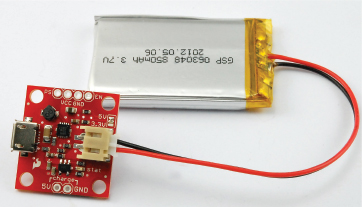
FIGURE 5-9 Combined LiPo charger and booster
This actually takes all the difficulties away from using a LiPo in a situation where you want to charge the LiPo battery in situ. Your 5V microcontroller circuit or whatever you are using is just attached to the VCC and GND connections, the battery is clipped into the socket, and to charge the device, you just plug in a USB cable.
Calculating How Long a Battery Will Last
We have already touched on the capacity of a battery—that is, the number of mAh it can supply. However, other factors come into play that we should think about when deciding if the batteries we are considering for a project are going to last long enough.
It’s really just a matter of common sense, but nevertheless it’s easy to make false assumptions about what you need.
As an example, I recently built an automated door for my chicken house. It opens at dawn and closes when it gets dark. It uses an electric motor, and electric motors use a lot of current, so I needed to decide what kind of batteries to use. My first thought was to use big D cells or a lead–acid battery. But when it came to do the math, I found this wasn’t really necessary.
Although the motor uses 1A each time it is in operation, it is only in operation twice a day, and each time only for about three seconds. I measured the control circuit as using 1mA all the time. So, let’s work out how many mAh the control circuit and motors each use in a day, and then see how many days various types of battery will last.
Let’s start with the motors:
1A × 3 seconds × 2 = 6As = 6/3600Ah = 0.0016 Ah = 1.6mAh per day
On the other hand, the controller, which I had assumed was the low power part of the project would consume:
1mA × 24 hours = 24mAh per day
This means we can pretty much ignore the power consumed by the motor since it is less than a tenth of the juice required by the controller. Let’s say the total requirement is 25mAh/day.
AA batteries are typically 3000mAh, so if we powered the project from AA batteries, we could expect them to last 3000mAh / 25mAh per day = 120 days.
So we do not really need to look much further, AAs will be fine. In the end, I used solar power for this project, which we will visit again in the section titled “How to Use Solar Cells” later in this chapter.
How to Design for Battery Backup
Replacing batteries is a nuisance, and expensive, so it is often cheaper and more convenient to power things from a wall-wart power supply. However, this brings its own disadvantages:
• The device is now tethered to a wire.
• If the household electricity fails, the device will stop working.
The best of both worlds can be achieved by arranging for automatic battery backup of a device that is powered by your household electricity. So, both batteries and a power supply are used, but the batteries are only used if the power supply is not available.
Diodes
What we do not want to happen is for both the batteries and the voltage from the power supply to conflict with each other when both are available. For instance, if the power supply is at a higher voltage than the batteries, it would charge them. But without anything to limit the current, this could be disastrous, even if the batteries were of the rechargeable sort.
Figure 5-10 shows the basic schematic for this. The power supply always needs to be a higher voltage than the battery, so in this case it is 12V and the battery 9V. The schematic also assumes that the battery backup is being used to drive a light bulb.
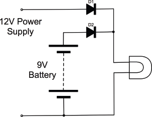
FIGURE 5-10 Battery backup schematic
Recall that diodes act rather like one-way valves. They only allow current to flow in the direction of the arrow. So, let’s look at the three possible cases of how power could be supplied here. This is simply the power supply: just batteries and both the battery and power supply (Figure 5-11).
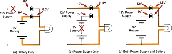
FIGURE 5-11 Diodes for battery backup
Just the Battery
If only the battery has a voltage greater than zero (in other words, the power supply is not plugged in), then the situation is as shown in Figure 5-11a. The 9V from the battery will be at the anode of D2, and the cathode of D2 will be pulled toward ground by the load of the light bulb. This will cause D2 to be forward-biased and conduct the current through the light bulb. A forward-biased diode will have an almost constant voltage of 0.5V across it, which is why we can say that the voltage after the diode is 8.5V.
On the other hand, D1 will have a higher voltage (8.5V) on its cathode (right-hand side in the diagram) than its anode (0V), so no current will flow through D1.
Just the Power Supply
If just the power supply is connected (Figure 5-11b), then the role of the diodes is reversed and now the current flows through D1 to the light bulb.
Both the Power Supply and the Battery
Figure 5-11c shows the situation where both the power supply and the battery are connected. The 12V of the power supply will ensure that the cathode of D2 is at 11.5V. Since the anode of D2 is at 9V from the battery, the diode will remain reverse-biased and no current will flow through it.
Trickle Charging
As we already have a battery and a power supply, we have most of the ingredients we need to charge the battery. We could for example use six AA rechargeable batteries in a battery box and arrange to charge them at C/20 (assuming C = 2000mAh) or 100mA from the power supply.
That way, the batteries would always be charged, and provide light whenever the power failed. Figure 5-12 shows the schematic for this.
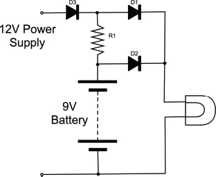
FIGURE 5-12 Battery backup and charging
You may not have been expecting the extra diode D3. This is really just to account for the fact that we do not know exactly how the power supply is designed, so we do not know what would happen if the battery was connected to its output (via R1) when it was turned off. This may discharge the battery or damage the power supply. The diode D3 just protects it and makes sure no current can flow back into it.
We want a charging current of 100mA to flow through R1, and we know that when both the power supply and battery are connected, there will be a voltage across R1 of 12V – 0.5V – 9V or 2.5V. So, using Ohm’s law, the value of the resistor should be:
R = V / I = 2.5 / 0.1A = 25Ω
The nearest standard value to this is probably 27Ω. Its power requirement: P = V2 / R = 2.52 / 27 = 0.23W This means a standard half- or quarter-watt resistor will be fine.
How to Use Solar Cells
On the face of it, solar cells seem like the perfect power source. They convert light into electricity, and so in theory you need never change a battery or be plugged into a wall outlet again!
However, as always, the reality is not quite so simple. Solar cells, unless they are very large, produce fairly small amounts of electricity and so are most suited to low-power devices and projects that are outdoors away from household electricity.
If you are thinking of trying a solar project that will be installed indoors, unless it will be sited against a south-facing window, I really wouldn’t try it. Solar cells do not require direct sunlight, but to produce any useful amounts of electricity, they really need a good unobstructed view of the sky.
Two solar projects I have developed are a solar-powered radio (the solar panel is as big as the radio and, yes, it needs to be next to the window), and a solar-operated chicken house door. If you are lucky enough to live somewhere sunny, then solar power is obviously a lot easier.
Figure 5-13 shows a typical solar panel. This one was scavenged from a security light installation. It is about six inches by four inches and has a swivel mount that allows it to be angled toward the sun. It is the panel I used for the chicken house door.
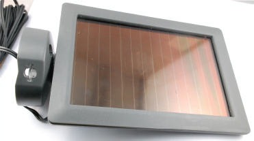
FIGURE 5-13 A solar panel
Projects that use a solar panel to provide power nearly always also use a rechargeable battery. So the panel charges the battery and the project draws its power from the battery.
Small solar cells generally only produce around half a volt, so they are usually combined into panels of many cells that increase the voltage to a level that is high enough to charge a battery.
The voltage you find on a solar panel normally refers to the voltage of battery that the solar panel is capable of charging. So, it is quite common to find 6V or 12V solar panels. When you measure the voltage from these in bright sunlight, the reading will be much higher, possibly 20V for a 12V panel. But, under the load of charging a battery, this drops rapidly.
Testing a Solar Panel
A solar panel will have a certain number of watts and a nominal voltage specified for it. These tend to be for ideal conditions, so when I get a solar panel that I want to use in a project, I like to test it to find what it is really capable of. Without knowing how much power it can provide in a real situation where it’s installed, it is hard to make safe assumptions about battery capacities and how low you need to keep the current consumption.
When testing out a solar panel, you should use a resistor as a “dummy load,” and then try out the solar panel in various locations and levels of brightness, measuring the voltage across the resistor. From this, you can calculate the current being provided by the panel.
Figure 5-14 shows such an arrangement for my “chicken house” solar panel. The meter is showing just 0.18V with a 100Ω load resistor inside the light box that I use for my photography. That equates to just 1.8 mA.
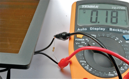
FIGURE 5-14 Testing a solar panel
I find a spreadsheet a useful way of recording how the solar panel performs. Figure 5-15 shows an excerpt from the spreadsheet, complete with graph. You can then file this away until the next time you wish to use a solar panel in a project.
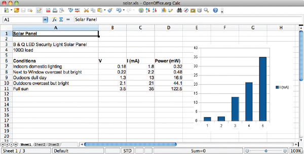
FIGURE 5-15 Solar panel data
The spreadsheet can be downloaded from www.hackingelectronics.com, but there is really nothing complex about the math.
As you can see, the solar panel produces only 1 or 2mA indoors even under bright artificial lighting. The results outdoors with a clear view of the sky are better, but it really only produces quite high power in direct sunlight.
Trickle Charging with a Solar Panel
Since the solar panels produce a reasonable voltage, even in relatively low light conditions, they can easily be used to trickle charge a battery. However, you should always use a diode to protect the solar panel from the situation where the battery is at a higher voltage than the panel (say at night), since such a reverse flow will damage the solar panel.
A typical simple trickle charge schematic is shown in Figure 5-16.
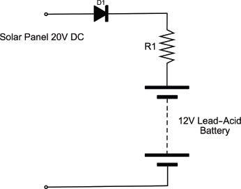
FIGURE 5-16 Schematic for solar trickle charging
Lead–acid batteries are still a very popular choice for trickle charging from solar. This is mainly because they are very forgiving of gentle over-charging and have a lower self-discharge rate than, say, NiMH batteries.
Minimizing Power Consumption
When planning solar power for some small outdoor project, you need to make sure the solar panel charging the battery can keep up with demand.
If you live in southern California, the design for using solar panels is pretty easy. You can count on quite a lot of sun all year long. However, if you live a long way from the equator, say, in a maritime climate where it’s often quite dull during the day, then you will have short winter days. You may get weeks of dull weather with short days. If your system is to work all year long, you either need to have a large battery that will last for a few weeks of dull weather, or use a larger solar panel.
The sums are pretty easy. There are mAh going into the battery from the solar panel, and mAh coming out for the device it is powering. The device might be running all the time, but the solar panel is only active half the time (daylight). So, you need to work out what you think the worst case for solar input might be for a week or two, and then design it accordingly.
It will probably be easier and cheaper to put your efforts into minimizing the current consumed by the system rather than increasing the size of the solar panel and battery.
Summary
In this chapter, we have learned about how to power our projects. In the next chapter, you will learn how to use the very popular Arduino microcontroller board.
..................Content has been hidden....................
You can't read the all page of ebook, please click here login for view all page.