
CHAPTER 18
![]()
Troubleshooting and Final Thoughts
We will close out this book with some tips in troubleshooting. When we think of troubleshooting a circuit, this can mean getting the circuit to work in terms of tracing an error in wiring, but troubleshooting also can relate to improving a circuit that was not designed optimally in the first place. Sometimes a circuit may not work at all in one type of construction, but it works perfectly when built on a different board. So troubleshooting involves both detective work and the builder’s flexibility to construct the circuit again in a different environment.
Assembling the Circuit
One of the ways to ensure that all the connections are made during construction of a circuit is to print a copy of the schematic. As each wire or component is soldered or connected, use a highlighter (marker) pen (e.g., yellow, pink, or green) to mark off each of the completed connections. Sometimes, with more complex projects, one may forget to hook up a power pin of an integrated circuit (IC) or ground a lead of a capacitor or resistor. The marking off of the schematic helps the builder keep track of what’s been wired. It is not uncommon to “finish” wiring a board just to find out in the schematic that one or two lines have not been highlighted and thus not connected.
When the Circuit Is Completed and Ready for a Test … Before Powering It On
If the circuit seems ready to power up, then first make sure that all the electrolytic capacitors are wired in the correct polarity. Incorrect connection of electrolytic capacitors can result in excessive current flowing into the electrolytic capacitor. A power supply with a current-limit adjustment feature comes in handy. For example, if the circuit is low power, you can set the current limit to about 50 mA. Otherwise, you can connect a 1 Ω to 10 Ω, ¼-watt series resistor between the power supply and the circuit. If there are any short circuits or excessive power drains, you can determine current by measuring the direct-current (DC) voltage across the series resistor and dividing the voltage by the resistance.
If you are testing an audio power amplifier, one old trick is to monitor the output terminals with a voltmeter without connecting the amplifier to a load. Connect a variac transformer to the power outlet, and hook up the variac autotransformer to the amplifier. The variac is first adjusted all the way down to 0 volt. Then slowly turn up the voltage to the full alternating-current (AC) line voltage. If the output terminals generate a huge DC offset voltage, quickly shut off the variac.
Another method as told to me by John Curl is to connect a standard 100-watt incandescent light bulb in series with the power supply to the power amplifier. If there are any shorted output transistors, the lamp will light up, and its resistance will rise due to heating of the filament and limit the DC current into the amplifier.
DC Bias Conditions
For determining the DC bias conditions of a circuit that does not include oscillators, measure various bias points with a voltmeter.
NOTE Measuring for a DC voltage where there is an AC voltage riding on top of the DC voltage usually results in erroneous measurements. It is better to use an oscilloscope instead for this case.
For NPN transistors, if the circuit is an amplifier, voltage across the base-emitter junction VBE has to be approximately 0.6 volt to approximately 0.7 volt. The range of collector-to-emitter voltage VCE is for VCE > 0.2 volts, and VCE is typically >1 volt. And for PNP transistors, the emitter-base voltage is in the 0.6 volt to 0.7 volt range, with the emitter-collector voltage VEC > 0.2 volt, typically >1 volt.
If for some reason the VCE for an NPN or VEC for a PNP transistor is less than 0.2 volt, one can try reducing the resistance value of the collector load resistor or increasing the associated emitter resistor. If that does not help, take out the transistor, and with an ohmmeter, measure any short circuit across the collector and emitter.
Transistors that are blown commonly have the following characteristics:
• The collector-emitter (or the collector-base) junction has become shorted to less than 10 Ω when measured with an ohmmeter both ways. By both ways, we mean to measure across the collector emitter with the positive probe on the collector and negative probe on the emitter and then measure again with the probes reversed. Some transistors that are fine (e.g., not shorted) have a diode across the collector and emitter and will measure in the approximately 15 Ω range depending on the ohmmeter in one direction but close to infinite resistance when the probes are reversed.
• The base-emitter junction has opened up, and the VBE voltage in the circuit exceeds 0.7 volt. With an ohmmeter and the transistor taken out, measure with the X1 resistance setting. A good transistor will measure typically less than 100 Ω in one direction and near infinite resistance when the probes are reversed. A blown base-emitter junction of the transistor will measure infinite resistance in both directions. In some Class AB amplifiers, where a biasing transistor is used as a VBE multiplier circuit to set the quiescent current of the output devices, the VBE multiplier circuit will fail if the base-emitter junction is blown or open circuited. This usually results in too much voltage across the bases of the output devices, resulting in excessive quiescent current that leads to failure of the output devices in the Class AB amplifier.
• It is rare, but it is possible that the base-emitter junction can be shorted, and if an ohmmeter shows low resistance in both directions, the transistor is bad.
For op amps with negative feedback used as an amplifier, the (+) input terminal’s DC voltage should force the (–) input terminal to the same voltage. For example, if the (+) input of an op amp is +3.5 volts DC, the (–) input terminal should also read +3.5 volts DC with a voltmeter. Note that the voltmeter should have a very high input resistance such as 10 MΩ, which is more common with FET analog voltmeters or digital volt-ohmmeters (VOMs) that cost more than $20 (e.g., as of the year 2014).
Choosing the Correct OP Amps
In many cases, a single-supply voltage powers a circuit that includes op amps. Both dual- and single-supply op amps are capable of working correctly with single or dual (+) and (–) supplies. The distinction for a single-supply op amp generally means that it can work off +5 volts on the supply, whereby the input stage can sense down to 0 volt, and the output terminal can still be operational at close to 0 volt. Some dual-supply op amps may work with +5 volts, but the input stage needs to be biased to about 2 volts to 2.5 volts, and the output stage will work within a narrow range around 2.5 volts.
For unipolar signals such as a photodiode preamp with the cathode of the photodiode connected to the (–) input of the op amp and the (+) input grounded, the output will have to swing above 0 volt. A single-supply op amp is recommend over a dual-supply op amp in this case.
One can perform a Google search for rail-to-rail op amps, which generally will work at +5 volts or with (±) power supplies. If the supply voltages are above 6 volts, usually one can get away with using dual-supply op amps by biasing the (+) input terminal to half the supply voltage.
Another consideration is that many of the newer op amps will have a maximum supply voltage of 10 volts to 16 volts across the power terminals. For example, high-speed op amps (as of 2014) generally have a +10 volt limit (or ±5 volts), such as the AD8038 and AD8005, and the TLC272 series op amps have approximately a +16 volt maximum (or ±8 volts) supply voltage. Many of the older op amps, such as the NE5532, RC4558, LM4562, and AD797, can handle 30 volts or ±15 volts safely.
What if you need more current output capability from an op amp? Most op amps have output short-circuit protection with current limiting to protect the output transistors. This current limit is typically about 10 mA to 15 mA, such as those found in the LM1458, LM358, and TL082. For higher output capability in the 25 mA or more range, one can use the NE5532, LM4562, LM833, or NJM4560 op amps.
Logic Gates with Increased Speed and Output Current
In some instances, a logic gate such as an inverter, flip-flop, etc. may be required to drive more than the input of another logic circuit. For example, a logic circuit may drive a light-emitting diode (LED) or a loudspeaker or even be used as a “final” power amplifier (PA) for a low-power radiofrequency (RF) transmitter. The 74AC or 74ACT series logic chips not only possess high speed (>50 MHz) but also provide output currents in excess of 30 mA compared with the lower-speed and lower-output current of the 74HC or 74HCT series logic chips.
Decoupling Capacitors
Typically, decoupling capacitors of 0.1 μF to 1 μF are placed at the power pins and ground in ICs. Ceramic or film capacitors are generally preferred, although sometimes electrolytic types can be used. Without them, ICs such as amplifiers can oscillate or digital ICs can output spurious pulses.
For other circuits, such as discrete transistor amplifiers or oscillators, usually there are at least two power-supply decoupling capacitors, which can include two or more ceramic or film capacitors or, alternatively, electrolytic capacitors. Preferably a larger-value electrolytic capacitor (e.g., at least 4.7 μF) is paralleled with a 0.01 μF to 1 μF ceramic or film capacitor. Electrolytic capacitors have equivalent internal series inductors, and at frequencies greater than 100 kHz, the impedance of the capacitors starts to flatten out and then rise. Ideally, a capacitor should have an impedance characteristic that continues to drop as the operating frequency rises.
The smaller-value ceramic or film capacitors have smaller equivalent inductors compared with electrolytic capacitors. When a ceramic or film capacitor is paralleled to an electrolytic capacitor, the parallel combination will have a dropping impedance characteristic as the operating frequency increases.
What to Do If an Amplifier Oscillates
In some cases, just the type of breadboard can cause some amplifiers to oscillate. For example, the superstrip protoboard has been found to cause certain LM386 audio amplifiers to oscillate. The capacitances between each row or each track were enough to cause an unsatisfactory operation of the LM386. A solution was to mount the LM386 IC on a vector board or to a copper-clad breadboard.
For a high-speed op amp or a transistor amplifier circuit, usually a 47 Ω to 100 Ω resistor connected in series to the (+) input of the op amp or to the base of the transistor should be enough to stop a parasitic oscillation. Of course, circuit layout is important, and input and base leads should be kept short.
When the output terminal of an op amp or amplifier is connected to the outside world, which includes capacitances from cables, to avoid oscillation, it is best to add a series 47 Ω to 100 Ω resistor between the output of the op amp or amplifier and the output connector. When working with low-voltage circuits of less than 40 volts DC of supply voltage, often the parasitic oscillation is of a high frequency, and if you have an oscilloscope set to 100 MHz analog bandwidth and probing the output, the location of the oscillation can be determined by touching parts of the circuit.
NOTE To avoid injury, do not touch higher-voltage circuits such as those that operate at greater than 40 volts.
Low-Frequency Oscillation
In some oscillator circuits, such as transformer-coupled types, often an AC coupling capacitor is included, such as the oscillator circuit in Figure 10-41. A condition known as squegging occurs when the AC coupling capacitor is generally too large in value and produces a low-frequency on-off modulation of the oscillator’s desired signal. For example, if the oscillator’s frequency is set to 455 kHz, as shown in Figure 18-1, capacitor C3, if too large in value (e.g., >1 μF), can cause the 455 kHz signal to turn on and off at a rate much lower than 455 kHz (see Figure 18-1).

FIGURE 18-1 AM radio local oscillator circuit with AC coupling capacitor C3.
One way to eliminate the squegging is to reduce the value of coupling capacitor C3 such that the oscillation signal is stable in amplitude. Typically, to avoid squegging, C3’s value is between 0.0047 μF and 0.012 μF. Larger values of C3 generally lead to the squegging problem.
Another type of parasitic low-frequency oscillation is motor-boating, which can be caused by an amplifier circuit with a series of RC power-supply filter circuits (see Figure 18-2). In Figure 18-2, the original value of C1 was 0.05 μF, which avoided motor-boating at Vout. However, to improve the low-frequency response, C1 was increased to 0.22 μF. This caused a positive-feedback effect due to the voltage change at C7’s positive terminal, effectively a shift in the power-supply voltage into vacuum tubes V1A and V1B.

FIGURE 18-2 A variant of the Dynaco PAS 3× phono preamp.
What happens is that the amplifier on startup pulls current and causes a delayed action of the power-supply voltage ramping up via R11 with C8 and R10 with C7. This causes the amplifier to reduce in current drain, and the supply voltage rises at C7 but then starts to increase in current and cause the voltage at C7 to decrease. This decreasing and increasing of voltage at C7 then provides a form of relaxation oscillation. The oscillation mimics the sound of a motor boat. If the voltage to the amplifier is made “stiffer,” the low-frequency oscillation is eliminated.
A fix to motor-boating can be done via a voltage regulator. Note that many older tube preamplifiers can suffer from motor-boating if modifications are done to increase low-frequency response. But often a simple voltage regulator will solve the problem (see Figure 18-3).

FIGURE 18-3 Voltage regulator circuit including ZD1, ZD2, and Q1 to eliminate motor-boating.
NOTE The circuits shown in Figure 18-2 and 18-3 use high voltages that can at least cause severe injuries, if not worse. Please do not attempt to build such circuits if you are not careful and familiar with high-voltage circuits.
The 600 volt regulator transistor Q1 should typically be a power MOSFET with a TO-220 case capable of handling several amps of drain current, such as a Vishay Siliconix IRFIB6N60APBF. The 150 volt zener diodes ZD1 and ZD2 connected in series form a 300 volt reference voltage that also reduces much of the ripple voltage from the raw +400 volt power supply. Further filtering of the 300 volt reference voltage is provided by R10/C9 and R11/C8. MOSFET Q1 is configured as a source-follower circuit that provides a low-impedance voltage source of about 300 volts. Zener diode ZD3 is connected to the gate and source of Q1, which provides current limiting and reverse-breakdown protection. Also note that R11 may be increased to 330 kΩ or even to 680 kΩ, if desired, for more power-supply ripple reduction.
Decoupling Sources from Injecting Noise into the Power Rails
One way to isolate noise from the power pins of circuits such as oscillators or logic gates is to use inductors and capacitors, as shown in Figure 18-4a. In some cases, larger-value inductors may be too expensive or may take up significant board space. If a slight voltage loss is acceptable, such as operating at 4.3 volts instead of 5.0 volts, an active inductor circuit that includes a transistor, resistor, and capacitor may be used (see Figure 18-4b).

FIGURE 18-4 (a) Using inductors to reduce noise coupling back into the main power-supply rail. (b) Using an active inductor Q1, R2, and C6 to equivalently provide larger inductance values.
In Figure 18-4b, transistor Q1 acts as a current source for AC signals. At DC or 0 Hz, capacitor C6 can be treated as an open circuit. With a high-current-gain transistor (e.g., β > 50), there are negligible base currents leading to close to a 0 volt drop across R2. This results in equivalently tying the collector and base together to form a diode, which leads to a 0.7 volt drop (e.g., 4.3 volts at the collector of Q1) and an output resistance of approximately 1/gm. For example, if the current drain is about 2 mA, gm = 2 mA/0.026 V = 0.0768 mho, and 1/gm = 1/0.0764 mho ≈ 13 Ω.
However, at higher frequencies, where C6 acts as an AC short circuit or a battery, the output resistance at the collector of Q1 is 2 kΩ via R2. This means that the noise from pin 14 of U1 has to couple through R2, a 2 kΩ resistor, before injecting noise into the 5 volt rail. Thus R2 provides isolation between the noise source from pin 14 of U1 and the 5 volt rail. One can increase R2 to a higher resistance value such as 10 kΩ, but there may be appreciable voltage drop across R2, and the voltage at the collector of Q1 will be less than 4.3 volts. If the current gain of the transistor is higher (e.g., β > 200), usually R2 can be increased in value to avoid incurring a larger voltage drop across it.
When an Oscillator Does Not Oscillate
For oscillators that should oscillate but do not, here are some suggestions:
• If the oscillator uses a transformer, try reversing either the outer primary or the secondary leads to ensure positive feedback.
• If the oscillator circuit has the correct phase for positive feedback and still does not oscillate, increase the collector current to provide more gain.
• Change the values of the positive-feedback network to provide more feedback.
• If the frequency of oscillation is beyond 20 MHz, try a higher-frequency transistor. For example, although general-purpose transistors such as the 2N3904 or 2N4124 can be used for a 100 MHz oscillator, often the collector current needs to be increased. A higher-frequency transistor such as the MPSH10 or 2N5179 should work better at lower collector currents.
See Figures 18-5a and 18-5b.
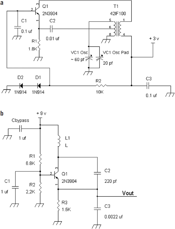
FIGURE 18-5(a) A transformer-coupled oscillator. (b) An example Colpitts oscillator circuit.
In Figure 18-5a, if the circuit fails to oscillate, one can try reversing the primary windings, pins 5 and 8, or reversing pins 1 and 4 of the secondary windings. Note that the low-side tap (T1, pin 6 to pin 8), which has the least measured resistance compared with the other primary windings, is usually coupled to the emitter of Q1. The output signal of the oscillator may be taken at pin 6 of T1 or at the emitter of Q1.
If the Colpitts oscillator in Figure 18-5b fails to start up, one can decrease the value of R3 from 1.5 kΩ to a resistance value as low as 330 Ω to provide more gain or transconductance in Q1. Alternatively, with R3 = 1.5 kΩ, the amount of positive feedback can be increased by providing more signal from the collector to the emitter. The approximate amount of voltage dividing is C2/(C2 + C3) ≈ 1/11 when C2 = 220 pF and C3 = 2,200 pF (0.0022 μF). One can try increasing C2 and decreasing C3. For example, try making C2 = 390 pF and C3 = 390 pF. If the oscillation frequency is greater than 20 MHz, change the transistor to a higher-frequency one, such as an MPSH10 or 2N5179.
It should be known that there are losses due to the inductors as well that can prevent an oscillator from starting up. Pertaining to different frequencies of oscillation, there are practical values for inductors. For example, in the range of 500 kHz to 3 MHz, one can use inductor values from about 1,000 μH to about 100 μH. For 3 MHz to 30 MHz, one can try inductor values from 100 μH to1 μH. And for frequencies from 30 MHz to 150 MHz, using inductor values from about 1 μH to 0.05 μH is a good start. In all these ranges, the larger inductance values should be used for the lowest frequency. For example, at 3 MHz, start at about 100 uH, and adjust to lower values as desired.
Reducing External Noise
Suppose that there is an audio mixer circuit that has been designed with high-value resistors in the 500 kΩ range and there is hum pickup from the AC line via fluorescent lamps or other external factors. One way to reduce hum pickup is to place the mixer circuit in a metal enclosure and connect the enclosure to a ground connection in the audio mixer circuit. But suppose that an enclosure for shielding out the external noise sources is not available? What’s an alternative?
We can lower the values of the resistors by hundredfold or more and reduce the noise by modifying the mixer circuit from 500 kΩ to 5 kΩ resistors (see Figure 18-6). Because many of the audio signal sources have low-impedance outputs, having an audio mixer circuit with lower input resistances, as shown in Figure 18-6, where the potentiometer’s resistance value is changed from 500 kΩ to 5 kΩ, is a solution to reducing external noise without loading down (too much) the audio sources.

FIGURE 18-6 Simple summing amplifier scaled to lower resistances to reject external noise sources.
When the Circuit Kind of Works
Sometimes when a circuit is built, the performance may not be up to par because one or two of the transistors have been inadvertently wired backwards, such as having emitter and collector leads reversed. When the collector and emitter leads are reversed, there is some transistor amplifying action, but the “reverse” current gain β is usually 1 or less versus when the transistor is wired correctly, when the forward current gain β is generally greater than 20. A consequence of having the collector and emitter leads reversed is that an amplifier may still work somewhat, but the DC base currents will be very large and will generate errors in the base DC biasing resistive network. Also, a reversed connection of the emitter and collector leads to a lower breakdown voltage of the transistor.
For example, did you know that if you want to make a cheap zener diode out of a transistor, just reverse bias the base and emitter terminals. Leave the collector terminal unconnected, or connect the collector to the base. For example, with an NPN transistor, ground the base lead, and connect a 1 kΩ to 10 kΩ resistor to the emitter. The other side of the resistor goes to a 12 volt or 9 volt power supply. A reference voltage between 5 volts and 8 volts will be available at the emitter reference to ground.
The actual breakdown voltage of the base-emitter junction will vary, and this “zener” voltage should not be construed as something reliable in terms of zener voltage accuracy. A quick experiment with a KN3904 or 2N3904 NPN transistor using a 1 kΩ resistor and a 9 volt battery resulted in a base-emitter breakdown or zener voltage of 7.64 volts at the emitter (Vout) with the base grounded (Figure 18-7).

FIGURE 18-7 An example of using an NPN silicon transistor for a zener diode.
Using an AM/FM Radio to Sense Whether an Oscillator Is Working
If you are troubleshooting a circuit that has an oscillator, there is a chance that an AM/FM radio will be useful in picking up the oscillator signal. For example, superheterodyne radios have local oscillators that can be picked up by another radio. For the standard AM band, the radio’s oscillator generates a signal from about 1 MHz to 2 MHz. A standard AM radio can tune from about 0.54 MHz to about 1.7 MHz. If you are repairing an AM radio, you can quickly find out if the converter or oscillator circuit is working by setting the dial to about 600 kHz and using another radio to listen for a drop in hiss at about 1,055 kHz. Some radios, such as the one mentioned in Chapter 17, the Sony ICF-S10MK2, has an LED signal-strength indicator, which also can be used to sense oscillator signals from another superheterodyne radio. An FM radio has a local oscillator with a range of about 99 MHz to 119 MHz, and an FM radio tunes from 88 MHz to 108 MHz, which would be able to pick the local oscillator signal from the other radio.
It should be known that with a lower-frequency oscillator, generally harmonics of the fundamental frequency are also generated. For example, a 100 kHz oscillator will generate signals that occur at frequencies of N × 100 kHz, where N is a natural number greater than or equal to 1, such as 1, 2, 3, …, 10, 11. Therefore, an AM radio will be able to pick up the 100 kHz oscillator at its harmonic signals at 600 kHz, 700 kHz, 800 kHz, 900 kHz, 1 MHz, 1.1 MHz, 1.2 MHz, and so on.
Using Low-Dropout Voltage Regulators
In some instances when a 12 volt DC power supply is built with a voltage regulator, the raw DC voltage drops just enough to cause the 7812 voltage regulator to pass some of the ripple voltage at its output. When the raw supply’s voltage falls to less than 13.7 volts (e.g., the rated regulated voltage plus 1.7 volts), the 7812 circuit fails to regulate the input voltage. A low-dropout voltage regulator such as the LM2940 requires only 0.5 volt above the regulated voltage or ≥ 12.5 volts at the input to provide a regulated 12 volt output. For the low-dropout regulator chips, bypass capacitors are generally a little larger in value. It is recommend that at least a 33 μF capacitor be connected across the output terminal and ground, and at least a 1 μF capacitor connected across the input terminal and ground.
Low-dropout regulator chips are available in different output voltages. For example, see the following links from Texas Instruments:
• www.ti.com.cn/cn/lit/ds/symlink/lm2940-n.pdf (for positive voltage regulators)
• www.ti.com.cn/cn/lit/ds/symlink/lm2990.pdf (for negative voltage regulators)
Back to Test Equipment
If I were to choose four pieces of test gear, they would be
• A good DVM that measures AC signals with a 2 volt or less full scale and measures beyond 10 MΩ in resistance with a transistor tester and frequency counter up to at least 1 MHz
• An oscilloscope that costs less than $1,000, such as the Rigol 1000Z Series (e.g, DS1104Z four-channel 100 MHz scope at $830); or for about $400 you can try the Rigol 1102E dual-channel 100 MHz scope
• A function generator up to at least 1 MHz
• An RF signal generator up to 100 MHz
One can make an audio signal tracer by using an amplified computer speaker. Also, by adding a germanium or Schottky diode in series with the hot or tip lead, demodulation of AM signals can be provided.
Summary on Troubleshooting
The art of troubleshooting generally takes a lot of experience, and as one gets to build or repair or modify existing circuits, the troubleshooting will become easier. The reader should always be aware that almost any design can be improved on in terms of reliability, performance, and so on.
One way to learn troubleshooting is to obtain some test equipment, build some circuits, and for example, probe with an oscilloscope if possible. Troubleshooting is like being a detective using a process of elimination. Usually, we start with whether the components have power and ground voltages, and later we look for the actual signals.
For example, there was the case of using a CD4046 phase-lock loop circuit. There are two phase detectors that one can select from—an exclusive OR logic circuit (phase comparator I) or a positive-negative pulse circuit that charges a capacitor (phase comparator II). According to the specification sheet, a typical AC signal at the input terminal 14 is 200 mV for both phase comparators. It was found that at 200 mV, phase comparator I indeed worked fine. However, phase comparator II required twice the signal level (400 mV) at pin 14.
Final Thoughts on the Book
When I mapped out this book in mid-2013, I had many ideas to choose from. Some of these were concepts that are no longer relevant to today’s generation, such as learning the resistor color code and working with coils. For example, it’s easier just to measure the resistor with an ohmmeter and build projects without coils or transformers. I learned quite a bit about what is more important today while mentoring some students at Stanford (thank you, Professor Bob Dutton!) in 2013 and 2014. So I decided to include some of the basics but also present projects that were not as nostalgic. In Chapter 11, for example, one of the FM radio projects uses no variable capacitors but instead a 2014 state-of-the-art Silicon Labs SDR (software defined radio) chip.
It’s been a pleasure to start this book with electricity projects involving LEDs, batteries, and lamps and then to progress to an intermediate level of electronics, including amplifiers and feedback systems. Finding more advanced projects up to Chapter 13 took quite a bit of selection as to what type of AM and FM radio projects to present along with a good system of circuits illustrated as the last big project, the video processor and scrambler.
In terms of math, I decided to just concentrate on lines and polynomials. Speaking of polynomials, I saw this “smart” answer on expanding the following:
(a + b)2 = (a + b)2
Of course, if I were the teacher, I would have given the student half credit because the answer “should have” been expanded this way:

I would have told the “smart” student that if you really want to expand (a + b)2, at least expand it in two dimensions (horizontally and vertically)! I would have also said, “Why think only in one dimension?” Just kidding!
NOTE Of course, the real answer is (a + b)2 = a2 + 2ab + b2.
Now I will present one last figure for this book. It’s a picture of the simple LED flashlight with two NiMh AA cells (low self-discharge types) that has been on since I wrote Chapter 4 (see the “original” Figure 4-11) during the first week of November 2013. Well, it is still on after over six months, and it probably will continue to give useful lighting past the last half of 2014 (see Figure 18-8).

FIGURE 18-8 Simple LED flashlight lit for over six months continuously.
Lastly, the material in this book has been more diverse than my first book, Build Your Own Transistor Radios, and I hope that at least some parts of Electronics from the Ground Up has resonated with the reader.
Thank you.
Ron Quan
20 May 2014
Postscript: As of September 15, 2014, the LED flashlight in Figure 18-8 is still giving off usable light. It has been on for over 10 months.