
As a summary of the theoretical and practical concepts learned so far, in this chapter we will build a simplified soft-phone application. We will first establish the scope of the application and its architecture. Then we will look at what the user interface looks like and what the relevant configuration parameters in the soft-phone are. The core of the soft-phone application implements a finite state machine that is analyzed in detail. Last, some ideas are given about possible further developments on the prototype soft-phone.
Building a full-fledged soft-phone application is a complex task. Actually, we would need a complete separate book in order to explain in detail how that could be done. That is not the purpose of this book. As we have stated in previous chapters, this book is about learning SIP-based multimedia communications, and, in order to accomplish this objective more effectively, we use simple programming examples. In the preceding chapters, we built some very simple examples that have allowed us to experiment with different aspects of SIP: transactions, dialogs, and so forth. We also learned how to encode and parse SDP objects, and we practiced with the media plane and the Real-Time Transport Protocol (RTP). Now is the moment to tie all these examples together in a single application that represents the summary of what we have learned. Such an application is a very simple, and limited in scope, soft-phone. The application is limited in scope for several reasons:
It does not implement all the functionality of a SIP UA. However, it implements the functionality that is needed for a basic example of peer-to-peer voice/video call.
We have deliberately omitted the bulk of error checking and recovery. This allows us to focus on the protocol details that otherwise would be lost among the numerous lines of code. So the code is not fully robust, and it will work just as long as it is fed with consistent user input.
It supports only the direct-routing model, so the simplified UA that we have implemented does not need to register with a registrar. In later chapters, we will enhance it so that it can work with an external SIP server.
It supports only two codecs for voice (GSM and G723), and two codecs for video (JPEG and H263). The caller decides what media to use: only audio or audio/video. The caller also selects just one codec for each media. The SDP negotiation is purposely very limited; it allows the called party just to accept or reject the video component, if it is present in the offer, based on the soft-phone configuration.
All in all, and in spite of the limitations, the application will be capable of setting up and releasing voice/video over IP calls, and, most importantly, it will contain the necessary elements to show the reader how a SIP soft-phone can be built and, in general, how SIP applications work.
In Chapter 3, we described how a multimedia communications application might look from a very high-level point of view. It was made up of four main components:
The user interface
The multimedia application core logic
A SIP UA
A number of media tools
Our soft-phone application will have an architecture that is aligned with that generic model. The differences are that, in our example, we will have only three media tools—one for voice, another one for video, and another one for the telephony signals (tones)—and we will have a separate component to deal with the SDP parsing and coding. In Figure 12.1, the soft-phone’s high-level architecture is presented.
The light boxes represent application components, and the dark boxes refer to components in the underlying JAIN SIP, JAIN SDP, or JMF implementation provided by third parties. Table 12.1 summarizes the third-party components that our application is using.
The application is running on top of the Java Virtual Machine (JVM), and comprises the following components:
User interface: It is implemented by the
Softphone1GUIclass, and shows the graphical user interface that allows the user to interact with the soft-phone.Soft-phone application core logic: It represents the core logic in our application, and is implemented by the
Softphone1Listenerclass. It consists of a finite state machine that receives events fromSoftphone1GUIand from the SIP stack, and coordinates the execution of all the other components.SIP implementation: In our case, it is the SIP stack from NIST, which offers a JAIN SIP 1.2 standard interface.
SDP manager: It is a custom wrapper software layer that abstracts and simplifies the functionality in the JAIN SDP API for the purposes of our soft-phone application. It was built in Chapter 9.
SDP implementation: It is the SDP stack from NIST, which implements the JAIN SDP interface.
VoiceTool: This custom component, which we created in Chapter 11, offers a simple API for capturing/presenting the voice media streams and transmitting/receiving them over the network. It uses the services of the Java Media Framework (JMF). It supports two audio formats: GSM and G723.
VideoTool: This custom component, which we created in Chapter 11, offers a simple API for capturing/presenting the video media streams and transmitting/receiving them over the network. It uses the services of the Java Media Framework (JMF). It supports two video formats: JPEG and H263.
TonesTool: This custom component, which we created in Chapter 11, offers a simple API for playing tones.
The JMF implementation: We will be using the JMF 2.1.1.e reference implementation from IBM and Sun. This piece of software implements the JMF Presentation API and the JMF RTP API.
Next we describe the interfaces between the different components.
This interface is used for three purposes:
to let
Softphone1GUIcommunicate the user interface events (e.g., user presses a button) toSoftphone1Listenerto let
Softphone1GUIcommunicate the softphone configuration toSoftphone1Listenerto let
Softphone1ListenerinstructSoftphone1GUIto render status information on the screen
For the first purpose, the custom userInput() method is used:
void userInput(int type, String destination)
It has two arguments:
type: It is an integer value that represents the type of GUI action that has occurred.
type = 0: user presses “Yes” button.
type = 1: user presses “No” button.
type = 2: user presses “Off” button.
destination: It is a String that represents the destination address input by the user. It makes sense only when type = 0; in other cases, its value will be ignored by
Softphone1Listener.
For the second purpose, we use two methods invoked on Softphone1 Listener:
Sphone1Listener(Configuration conf,Sphone1GUI GUI)
void updateConfiguration(Configuration conf)
the
Softphone1Listener()constructor method that is invoked when the user presses the “On” button and triggers the creation of a new instance ofSoftphone1Listener.The
updateConfiguration()method that is invoked whenever the user presses the “Apply Configuration” button in the configuration area, typically after the user changes some configuration parameters. This method causesSoftphone1Listenerto update the class variables that store the soft-phone configuration parameters.
Both methods include a Configuration object that encapsulates the soft-phone configuration. The Configuration class is described in Section 12.5, “Implementation Aspects.” Additionally, the Softphone1Listener constructor method also includes as an argument a reference to the Softphone1GUI object so that, later on, Softphone1Listener can invoke the methods described next for the “third purpose.”
For the third purpose, we use a method invoked on Softphone1GUI:
void showStatus(String text)
The showStatus() method is used to display status information (represented by the text argument) on the soft-phone user interface, such as phone is ringing, call is established, and so on.
This interface is shown in Figure 12.2.
This interface complies with the JAIN SIP 1.2 specification.
This interface offers two methods:
byte[] createSdp(SdpInfo sdpinfo)
SdpInfo getSdp(byte[] content)
createSDP():Creates an SDP message based on the key relevant parameters for the application.getSDP():Obtains the relevant SDP parameter for the application from a SDP message.
This interface is shown in Figure 12.3.

This interface complies with the JAIN SDP specification.
This interface is used for Softphone1Listener to instruct VideoTool to start/stop transmission or reception of voice streams.
The following methods are used that were explained in Chapter 11:
int startMedia(String peerIP,int peerPort,int recvPort, int fmt)void stopMedia()
This interface is shown in Figure 12.4.

This interface is used for Softphone1Listener to instruct VideoTool to start/stop transmission or reception of voice streams.
For this purpose, the following methods are used that were explained in Chapter 11:
int startMedia (String peerIP,int peerPort,int recvPort, int fmt)void stopMedia()
This interface is shown in Figure 12.5.
This interface is used for Softphone1Listener to instruct TonesTool to play a ringing tone or an alerting signal during the call-establishment phase if needed.
The following methods are used that were explained in Chapter 11:
void prepareTone (String filename)void playTone ()void stopTone()
As a summary of the architecture topic, Figure 12.6 shows the different components in our application and the interfaces between them.
Our soft-phone offers a very simple graphical interface. It consists of two differentiated areas: the user interaction area and the configuration/display area. This is depicted in Figure 12.7.
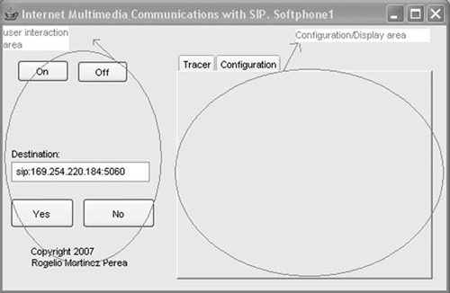
The user interaction area contains a number of components that allow the user to switch on/off the soft-phone as well as to place and release calls. The components are described next.
Once the configuration tab in the configuration/display area (see next section) has been filled in, the user will “switch on” the phone by pressing the “On” button. It is important that the configuration is done before the user presses “On,” otherwise the SIP initialization will fail.
Pressing the “On” button will cause Softphone1GUI to invoke the constructor method for SipListener. This method will retrieve the machine’s IP address and show it in the GUI (in the configuration tab). The execution of this method will also initialize the JAIN SIP environment and update the Softphone1Listener class variables that store the configuration parameters. The soft-phone automatically enters into the IDLE state, and is therefore ready to generate or receive calls.
If the user presses the “Off” button, the close() method is invoked on Softphone11Listener. This method contains the code necessary to shut down the SIP environment. If there is an ongoing call and the user wants to switch off the phone, given that our soft-phone does not include all the code for error checking and recovery, we recommend users to first release the call by pressing the “No” button before pressing the “Off” button.
Below the “On” and “Off” buttons, there is an information panel that will appear as soon as the phone is started (“On” button pressed). This panel will give us information on the call state: idle, alerting, ringing, established. Phone1Listener will call the showInfo() method on the Softphone1GUI in order to write specific text on the Info label.
This text field must be filled in by the user; it represents the identity of the desired recipient of the call. Because we are using direct routing in this example, the address will have the format:
sip:IPaddress:port or
sip:userinfo@ IPaddress:port
This button is used in two scenarios:
to initiate a new call
to accept an incoming call
Pressing the “Yes” button will cause Softphone1GUI to invoke the userInput() method with type=YES on Softphone1Listener.
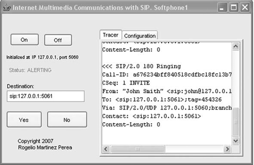
The configuration/display area is located at the rightmost part of the GUI. It consists of a JTabbedPane with two tabs. The first tab is the tracer display, where the signaling messages sent or received by the soft-phone will be shown in realtime. This is depicted in Figure 12.8.
The other tab contains the configuration area (shown in Figure 12.9), which is itself divided into two parts. The topmost half is the user configuration area. It includes a number of configuration parameters related to the user or to the UA. These parameters need to be filled in before the soft-phone is started (i.e., before “On” is pressed). Once the phone has been started, these parameters cannot be changed. These parameters are:
SIP UDP port: That is the port that our application will use to send and receive the SIP messages.[1] The default value for SIP is 5060.
User identity: Given that, in this example, we are using the direct-routing mode (no proxies), the user identity contains the IP address of the machine where the soft-phone is running. This is automatically filled in by the application when the user presses the “On” button. The user will just need to enter the userinfo part of the identity.

The bottom most half of the configuration tab contains media-related parameters. These can be changed at any time. In order for the changes to take effect, we need to press the button “Apply media configuration.” The changes will be effective from the next placed or received call. These parameters are:
User name: It represents the name that will appear in the display-name field of the From header for outgoing calls from this soft-phone.
Voice RTP port: This is the port where our application expects to receive the voice RTP packets.[2] This port will appear in the voice media line in SDP offers sent by the soft-phone.
Video RTP port: This is the port where our application expects to receive the video RTP packets. This is the port that will appear in the video media line in SDP offers sent by the soft-phone.
Media: Two options are possible—audio only or audio plus video. The value of this configuration parameter has two effects:
When our soft-phone originates a call, the SDP offer will contain just audio or audio/video, depending on the configuration parameter.
When our soft-phone receives a call containing audio and video, it will reject the video component if the media configuration parameter is set to audio only.
Voice codecs: Two options are given—GSM or G723. It is either one or the other. The soft-phone will include only one codec in the SDP offer.
Video codecs: Two options are given—JPEG or H263. It is either one or the other. The soft-phone will include only one codec in the SDP offer.
The configuration tab of our soft-phone is shown in Figure 12.9.
The class Softphone1Listener is the core component in the system. It receives network events from the SipProvider, and method calls from the GUI.[3] It can invoke methods on the SipProvider, the GUI, the SdpManager, or the media tools. It is the central intelligence point where the soft-phone logic is implemented. This is depicted in Figure 12.10.

The way Softphone1Listener implements the core logic is through a finite state machine. It defines a number of states and the events (implemented as Java events or method calls) that cause a transition from one state to another.
In order to show the state model, we will use a diagram in which states are represented together with the transitions between them. Each state is given a name, and shows arrows coming into it or going out of it. The incoming arrows represent events that trigger the transition to that state. The outgoing arrows represent the transition to the next state. Each arrow has one label associated with it. The label represents the name of the event that triggers that transition. Next to it, there is, in some cases, the name of the main action that is executed when the event is triggered. This general scheme used for the diagram is shown in Figure 12.11.

Figure 12.12 shows the soft-phone state model. As we said at the beginning of this chapter, this application is very simplified. This is also reflected in the simplicity of the state model that we are using.

Next is a description of the different states and the events and actions associated with them. For each state, we highlight which are the events that cause the soft-phone to reach that state (incoming events), and which are the events that cause the soft-phone to leave that state (outgoing events).
This is the state the soft-phone enters when it is switched on (“On” button is pressed). It represents absence of active calls. The phone is ready to originate or receive calls. Whenever calls are completed, the phone comes back to the IDLE state.
The calling user presses “No” when the call is proceeding, causing a CANCEL to be issued. Please note that this implies that there may be a residual pending CANCEL transaction for a small amount of time while in IDLE state. This fact does not interfere with the correct working of the soft-phone.[4]
The called user presses “No” in order to reject an incoming call.
Timer for the ACK expires, which causes the application to release the session.
The calling or called user initiates a call release (user presses “No,” resulting in the sending of a BYE) or receives a call release (receive a BYE). Please note that this implies that there may be a residual pending CANCEL transaction for a small amount of time while in IDLE state. This fact does not interfere with the correct working of the soft-phone.
This state is entered when the phone sends an INVITE, and is not left until it receives a provisional or final response.
A provisional response is received, in which case a transition to the WAIT_FINAL state occurs.
A final response is received, causing the phone to send an ACK request. The soft-phone transits to the ESTABLISHED state, and it will start transmitting and receiving media.
The user presses the “No” button, and a CANCEL request is generated. The soft-phone goes to IDLE.
In this state, a provisional response to an INVITE has been received, and the phone is waiting for the final response.
This state represents the situation where the call is active and the session fully established between the two peers.
This is the state produced when a call has been received and a 180 provisional response has been generated, but the call has not yet been accepted.
The called user accepts the call and generates a 200 OK. The soft-phone transits to WAIT_ACK.
The called user rejects the call and generates a 486 final response. The soft-phone moves back to IDLE.
A CANCEL request is received for the ongoing transaction. The transaction is terminated with a 487 response. The soft-phone moves back to IDLE.
This state represents the situation where a call has been accepted, but the ACK message has not yet been received.
The implementation of the state model described in the previous section is straightforward because it mainly reuses the code that we already described in previous chapters. There are, though, some new implementation aspects, not tackled so far, which we will highlight next.
The soft-phone configuration is entered by the user in the configuration area of the user interface. At phone start-up, or whenever the user presses the “Apply Configuration” button, the configuration parameters are conveyed, as a Configuration object to Softphone1Listener in the userInput() or updateConfiguration() methods.
The Configuration class is just a data structure to hold the parameters entered by the user:
public class Configuration {
   int sipPort=5060;
   String name=" ";
   String userID=" ";
   int audioPort=40000;
   int videoPort=50000;
   int audioCodec=3;
   int videoCodec=26;
   public Configuration() {}
   public void setSipPort(int sp) { sipPort=sp;}
   public void setName(String nm) {name=nm;}
   public void setUserID(String UID) {userID=UID;}
   public void setAudioPort(int AP) {audioPort=AP;}
   public void setVideoPort(int VP) {videoPort=VP;}
   public void setAudioCodec(int AC) {audioCodec=AC;}
   public void setVideoCodec(int VC) {videoCodec=VC;}

   public int getSipPort() {return sipPort;}
   public String getName() {return name;}
   public String getUserID() {return userID;}
   public int getAudioPort() {return audioPort;}
   public int getVideoPort() {return videoPort;}
   public int getAudioCodec () {return audioCodec;}
   public int getVideoCodec () {return videoCodec;}
}
A situation where the media configured by the user is “Audio only” is represented by giving the videoPort field in the Configuration object a value of – 1.
On the other hand, the configuration parameters are stored in Softphone1Listener in the following class variables:
private int myPort; // this represents the SIP UDP port
private int myAudioPort;
private int myVideoPort;
private int myAudioCodec;
private int myVideoCodec;
Again, if myVideoPort=-1, it means that the user has configured “Audio only” media.
When the calling user presses the “No” button while in the WAIT_FINAL state, his or her soft-phone generates a CANCEL request. JAIN SIP offers the createCancel() method in order to create a CANCEL request from the original client transaction that the user wants to cancel. Once the CANCEL has been created, we will need to get a new client transaction through which we will send the CANCEL request:
Request myCancelRequest = myaClientTransaction.createCancel();
ClientTransaction myCancelClientTransaction =
  mySipProvider.getNewClientTransaction(myCancelRequest);
myCancelClientTransaction.sendRequest();
The called user will receive the CANCEL request while in the RINGING state. At that point, his or her phone must terminate the INVITE transaction with a 487 (Request terminated) response, after which it must respond to the CANCEL transaction itself with a 200 OK:
ServerTransaction myCancelServerTransaction=
  requestReceivedEvent.getServerTransaction();
Request originalRequest=myServerTransaction.getRequest();
Response myResponse=
  myMessageFactory.createResponse(487,originalRequest);
myServerTransaction.sendResponse(myResponse);
Response myCancelResponse=
  myMessageFactory.createResponse(200,myRequest);
myCancelServerTransaction.sendResponse(myCancelResponse);
Tags in the From and the To header, together with the CallID, are used to identify a SIP dialog. The tag in the From header is set by the calling UA, and provides only half of the dialog identification. The other half is set by the recipient of the request by including a tag in the To header of provisional and successful final responses.[5] RFC 3261 states that UAs need to compute the tag in such a way that it is globally unique and cryptographically with at least 32 bits of randomness. The actual algorithm for generating a tag is implementation-specific.
In previous examples, we always used the same tags in the From and To header. Readers may want to enhance their soft-phone implementation by generating truly random tags. A possible option is to use the SecureRandom class provided in the standard java. security package. This class provides a cryptographically strong pseudo-random number generator. The following code generates a set of random bytes.
numBytes == 4; //adequate for the From/To tag;
byte[] rand = new byte[numBytes];
SecureRandom random = SecureRandom.getInstance("SHA1PRNG");
random.nextBytes(bytes);
In order to use it in the From or To header we would need to convert the byte array into a string that is safe to use in SIP headers. We could, for instance, use Base64 encoding. There are a number of open source Base64 encoders that readers may use.
As we said at the beginning of this chapter, our soft-phone application is very simplified. This is also reflected in the simplicity of the state model that we are using. This call model is not catering for all the possible error conditions and timeout situations. More specifically, this state model does not respond to timeout events in the transaction layer. This means that when timers in the transaction layer expire, the transaction is terminated, but the application takes no specific action.
The state model also reflects the situation that the application is not taking care of any message retransmission whatsoever. As was explained in Chapter 7, the transaction sublayer takes care of retransmissions at that level. End-to-end retransmissions of INVITE, 200 OK, and ACK are handled by the JAIN SIP dialog implementation as corresponds to the fact that the SipStack property RETRANSMISSON_FILTER is set to ON.[6] Regarding the INVITE transaction, there is, though, one aspect not specifically addressed by the JAIN SIP spec that the application therefore needs to implement. This refers to the situation when a UAS keeps sending retransmissions of the 200 OK response to an INVITE, but it does not receive any ACK. RFC 3261 states that the UAS core (in our case, it will be the dialog object) keeps retransmitting the 200 OK responses for 64*T1[7] seconds, after which, if no ACK was received, the UAS needs to terminate the session by sending a BYE. This particular behavior is implemented in the state model by the explicit consideration of state WAIT_ACK and its associated timer.
The following code shows how this timeout situation is implemented in our application.
First we create a class in the declaration section of Softphone1Listener that extends the abstract class TimerTask. In its run() method, we include all the code that needs to be executed when the timer expires:
class MyTimerClass extends TimerTask {
   Softphone1Listener myListener;
   public void MyTimerTask (Softphone1Listener myListener){
      this.myListener=myListener;
   }
   public void run() {
      Request myBye=myListener.myDialog.createRequest("BYE");
      myBye.addHeader(myListener.myContactHeader);
      myListener.myClientTransaction=
      myListener.mySipProvider.getNewClientTransaction(myBye);
      myListener.myDialog.sendRequest(myListener.myClientTransaction);
   }
}
In addition to defining this class, we also need to start the timer when a transition occurs from the RINGING state to the WAIT_ACK state. That is, we need to add the following code if the YES button is pressed when in the RINGING state:
new Timer().schedule(new MyTimerTask(this),60000);
Another important assumption in the soft-phone implementation is the fact that it will not support more than one simultaneous call. During the process of call management, there will be one main transaction (either INVITE or BYE) that refers to the existing call. There may also be a parallel CANCEL transaction in case the user has tried to abort the call before it is established. In those cases where the user releases a call and immediately initiates another one, it may happen, if transport conditions are not good, that the new INVITE transaction starts before the BYE transaction is terminated (200 OK received). The soft-phone implementation will not be aware of those situations—it will just let the transaction sublayer decide when the transaction needs to be finalized. From the application point of view, the only transaction to worry about is the new one.
So we will define the following object variables at class level to refer to the main transaction at every moment in time:
myClientTransaction:It represents the main non-CANCEL client transaction at any moment in time.myServerTransaction:It represents the main non-CANCEL server transaction at any moment in time.
We will also use the following variables to represent the parallel CANCEL transaction, if one exists:
myCancelClientTransactionmyCancelServerTransaction
Another aspect in our soft-phone application that is different from the practices done so far in the book is the reception of 4XX responses, such as the 486 (Busy Here) response that the soft-phone will receive if the called party is busy or rejects the incoming call. When such a response is received, the underlying client transaction implementation will automatically generate an ACK request, therefore our application does not need to bother with that aspect.
[RFC 3264] describes the SDP offer/answer model. Among other things, it describes possible options to activate the media reception and transmission at the different steps in the model. The approach that we will be taking is based on the following considerations:
The calling party sends the SDP offer.
The called party receives the offer and generates an answer. As soon as the SDP answer is sent, the answerer commences media transmission and starts listening on the receive ports specified in the SDP answer.
When the offerer receives the SDP answer, it starts listening on the receive ports that were specified in the SDP offer; and commences media transmission.
This is depicted in Figure 12.13.
Additionally, we make some assumptions[8] as to the way the SDP is configured and manipulated by the soft-phone. These assumptions allow us to simplify the code and to focus on the fundamental concepts. Next we describe in detail the different aspects of SDP and media handling. At each step, we will highlight the assumptions that we have made.
In order to manipulate the SDP, we will use the SdpManager class, which was introduced in Chapter 9. Likewise, in order to handle the media, the classes VoiceTool and VideoTool, which were described in Chapter 11, will be utilized.
In any case, in order not to complicate the soft-phone implementation, we do not include code for the cases where the execution of startMedia() fails. It is left as an exercise to the reader to add the necessary code that causes the soft-phone to move to IDLE if these methods fail.
In order to build the SDP offer, our soft-phone will check the media configuration parameters. If the configured media is audio only, then the SDP will contain only an audio m-line. If, on the other hand, it is audio and video, the SDP will contain an audio m-line and a video m-line.
The offered codecs are also taken from the configuration parameters: myAudioCodec and myVideoCodec. These were introduced by the user in the soft-phone configuration area, and conveyed to Softphone1Listener in a Configuration object. The SDP will contain only one codec per media.
The ports for audio and video are taken from the configuration parameters: myAudioPort and myVideoPort. These were introduced by the user in the soft-phone configuration area:
offerInfo=new SdpInfo();
offerInfo.setIpAddress(myIP);
offerInfo.setAudioPort(myAudioPort);
offerInfo.setAudioFormat(myAudioCodec);
offerInfo.setVideoPort(myVideoPort);
offerInfo.setVideoFormat=(myVideoCodec);
ContentTypeHeader contentTypeHeader=
  myHeaderFactory.createContentTypeHeader("application,""sdp");
byte[] content=mySdpManager.createSdp(offerInfo);
myRequest.setContent(content,contentTypeHeader);
If the video component is not desired, vPort and vformat are set to - 1, causing the SdpManager to not include the video m1000-line in the SDP.
When an INVITE is received that contains an SDP offer, the UA will get the SDP content and obtain the relevant parameters (ports and codecs):
byte[] cont=(byte[]) myRequest.getContent();
offerInfo=mySdpManager.getSdp(cont);
Next we build the SDP answer with the following parameters:
The audio port in the answer is the configured port for audio (
myAudioPort).The audio format in the answer is the same as the audio format in the offer.
If the offer does not contain a video m-line, then the answer will not contain it either (
vport=-1).If the offer contains video, but the recipient UA wants only audio (configured
myVideoPort=-1), then the video component is rejected (vport=0):answerInfo.setIpAddress(myIP); answerInfo.setAudioPort(myAudioPort); answerInfo.setAudioFormat(offerInfo.getAudioFormat()); if (offerInfo.getVideoPort()==-1) { answerInfo.setVideoPort(-1); } else if (myVideoPort==-1) { answerInfo.setVideoPort(0); answerInfo.setVideoFormat(offerInfo.getVideoFormat()); } else { answerInfo.setVideoPort(myVideoPort); answerInfo.setVideoFormat(offerInfo.getVideoFormat()); }
When the called party accepts the call, he or she issues a 200 OK that contains the SDP answer previously calculated. It will also start listening for media and will start transmitting media:
ContentTypeHeader contentTypeHeader=
myHeaderFactory.createContentTypeHeader("application, ""sdp");
byte[] content=mySdpManager.createSdp(answerInfo);
myResponse.setContent(content,contentTypeHeader);
myVoiceTool.startMedia(offerInfo.getIpAddress(),offerInfo.
  getAudioPort(),answerInfo.
   getAudioPort(),offerInfo.getAudioFormat());
if (answerInfo.getVideoPort()>0) {
   myVideoTool.startMedia(offerInfo.getIpAddress(),offer
     Info.getVideoPort(),
      answerInfo.getVideoPort(),offerInfo.getVideoFormat());
}When the calling party receives the 200 OK, it will start listening on the receive ports for the offered media. It will also extract the SDP answer and will start transmission of media toward the address present in the answer:
byte[] cont=(byte[]) myResponse.getContent();
answerInfo=mySdpManager.getSdp(cont);
myVoiceTool.startMedia(answerInfo.getIpAddress(),answerInfo.
  getAudioPort(),offerInfo
   .getAudioPort(),answerInfo.getAudioFormat());
if (answerInfo.getVideoPort()>0) {
   myVideoTool.startMedia(answerInfo.getIpAddress(),answer
     Info.getVideoPort(),
      offerInfo.getVideoPort(), answerInfo.getVideoFormat());
}We also need, in our soft-phone implementation, to stop media transmission and reception as soon as a BYE request is sent or received.
If the soft-phone is in established state and it receives a BYE request, then we need to add the following code:
myVoiceTool.stopMedia();
if (answerInfo.getVideoPort()>0) {
   myVideoTool.stopMedia();
}
Likewise, when the soft-phone is in established state and the user presses “No,” the soft-phone will send a BYE request. In addition to that, we need to stop the media session. So we must again include the same code as before:
myVoiceTool.stopMedia();
if (answerInfo.getVideoPort()>0) {
   myVideoTool.stopMedia();
}Our soft-phone will need to play an alerting signal when an INVITE is received, or play a ringing tone when it receives a 180 Ringing provisional answer. For that purpose, we will use the TonesTool class, which we built in Chapter 11.
As soon as the soft-phone is started, we will create two instances of TonesTool: one for the alerting signal, and the other for the ringing tone. Additionally, we will prepare the DataSource objects by calling the prepareTone() method, passing as an argument a string that represents the location of the file containing the audio tone.
Thus, in the Softphone1Listener’s constructor method, we will include:
myAlertTool=new TonesTool();
myRingTool=new TonesTool();
myAlertTool.prepareTone("file://c:\alert.wav");
myRingTool.prepareTone("file://c:\ring.wav");
The alert.wav and ring.wav files MUST be present in the c:\ root directory, otherwise the program execution will fail.
The alerting signal will be played by the called party,s soft-phone when an INVITE is received in IDLE state:
myAlertTool.playTone();
In order to stop the alerting signal, we will include the following code:
myAlertTool.stopTone();
in the following situations:
Called party accepts an incoming call by pressing “Yes” in RINGING state.
Called party rejects an incoming call by pressing “No” in RINGING state.
Called party receives a CANCEL request when in RINGING state.
The ringing signal will be played by the calling party’s soft-phone when a 180 provisional response is received in either the WAIT_PROV or WAIT_FINAL states:
myRingTool.playTone();
In order to stop the ringing signal, we will include the following code:
myRingTool.stopTone();
in the following situations:
A 200 OK is received in the WAIT_PROV or WAIT_FINAL states.
The calling party presses “No” when in WAIT_FINAL state.
The calling party receives a 603 response message because the call is declined by the called party.
The full code for the application can be downloaded from the book’s web page (see Appendix A).
Figure 12.14 shows a snapshot of two communicating user agents. In this case, both user agents are running in the same machine, but with different ports. Although this is an approach that allows us to look at the signaling exchanges, it does not allow us to experience the media side. For a full-fledged, end-to-end scenario also including the media, two PCs are needed, one for each user agent.

In this chapter, we have put into practice the concepts learned so far about SIP, SDP, and RTP. The soft-phone that we built was not registered with a registrar server, and thus we needed to know the called party’s IP address beforehand. That is not a practical scenario. In a real scenario, there are SIP servers that at least handle the user location and routing aspects. Our target is to build a realistic scenario, so, in the next chapter, we will examine in detail the SIP proxy behavior, and build a proxy and a registrar that can work in conjunction with our soft-phone.
[1] It is a UDP port because our soft-phone application will use only UDP as transport for the SIP signaling.
[2] Following the recommendation in [RFC 3550], the port for RTCP packets that we will be using is RTP port +1, so there is no need to explicitly specify it.
[3] As was explained in previous sections, there is also a scenario in which Softphone1Listener receives a method call from the VideoTool when a video component in detected.
[4] Another approach to deal with this situation might be to define a new state before reaching IDLE, which is left only if 200 OK to CANCEL is received. This would mean that in faulty transmission situations, it might take some time for the user to be able to initiate a new call. For the sake of this leaning exercise, we will not define such a state.
[5] The tag in the To header, set by the recipient, helps the originating UA to disambiguate the multiple dialogs established from a single request in those cases where there is a forking proxy between calling and called parties.
[6] RETRANSMISSION_FILTER has a default value of ON. Let us recall that in this application, we are using all default values of SipStack properties. The only exception is the SipStack name.
[7] T1 represents the round-trip delay (RTT) and is typically assumed to be 500 ms.