
Chapter 11. Standard protocol for exchanging system facts
Abstract
System assurance requires a common vocabulary for describing accurate system facts to represent concrete facts about the system of interest. It is the foundation for the integrated system model, to which other units of cybersecurity knowledge can be added, as well as the foundation for describing general cybersecurity content, such as vulnerability patterns. The standard protocol for exchanging system facts is described in the OMG Knowledge Discovery Metamodel (KDM). The KDM model contains facts corresponding to all system assurance viewpoints, interconnected with vertical traceability links as well as horizontal relationships across multiple vocabularies. Traceability links is one of the key mechanisms of the KDM protocol, enabling integration between high-level system facts, such as the systems and operational views, risk views, supply chain views and life-cycle processes views, and the high-fidelity facts extracted directly from various machine-readable artifacts of the implementation of the system, including source and binary files, network configuration, runtime platform configuration, and database descriptions.
Keywords
knowledge discovery metamodel, kdm, software assurance ecosystem, knowledge discovery, information exchange, common vocabulary, system facts, viewpoint, view
The principle difficulty in your case lay in the fact of there being too much evidence. What was vital was overlaid and hidden by what was irrelevant. Of all the facts which were presented to us we had to pick those which we deemed to be essential, and then piece them together in their order, so as the reconstruct this very remarkable chain of events.
—Arthur Conan Doyle, The Adventure of the Naval Treaty
Facts that are concealed acquire a suspicious importance. Facts that are frankly revealed tend to be regarded as less important than they really are.
—Agatha Christie, Thirteen at Dinner
11.1. Background
Knowledge Discovery Metamodel (KDM) is a publicly available specification from the Object Management Group (OMG) [KDM]. The initial proposals for the specification were provided by several companies in the software modernization space, including IBM, Unisys, and Electronic Data Systems (now a division of Hewlett-Packard). The specification was developed during the years 2003–2006 by a group of 12 companies. The KDM specification was adopted by the OMG in 2006 and is maintained by a dedicated revision task force. The current version of the KDM specification is KDM 1.3. It is being adopted by ISO as ISO/IEC 19506 [ISO 19506].
KDM was designed as OMG's common foundation for “modeling in reverse,” that is, performing fact-oriented analysis of existing software-intensive systems for the purposes of software modernization and software assurance. KDM standardizes existing approaches to knowledge discovery in software engineering artifacts, or software mining. The key requirement for “modeling in reverse” is a model of system artifacts that can be built bottom-up, normalizing the differences in programming languages and vendor-specific runtime environments.
KDM provides such a common representation for existing software systems and their operating environments and defines a body of shared meanings required for exchanging facts about systems during diverse assessment projects involving existing software intensive systems.
KDM defines a standard protocol for exchanging system facts that allows interoperability between existing software analysis and modernization tools, services, and their respective proprietary formats. KDM protocol is the foundation for the OMG Assurance Ecosystem, as described in Chapter 8. More specifically, KDM defines a common vocabulary and an interchange format that facilitates the exchange of data that is currently contained within proprietary programming language-specific and vendor-specific models. The metamodel represents the physical and logical elements of systems as well as their relationships at various levels of resolution.
KDM arranges facts about existing systems into several viewpoints each of which corresponds to an ISO 42010 architectural viewpoint. Following the fact-oriented approach, KDM focuses on the entities and their relationships that are essential for each viewpoint, formalizing the common vocabulary for the viewpoint (the viewpoint language). A KDM representation of a given software system—KDM views—is a collection of facts about that system. KDM supports the Common Fact Model, described in Chapter 9, in such a way that the KDM elements are standard “locations” of the system of interest, to which information from additional non-KDM vocabularies can be easily integrated. KDM views become part of the complete architectural description of the system, as defined by ISO 42010.
KDM views are represented as XML documents conforming to the KDM XMI schema. KDM uses OMG's Meta-Object Facility (MOF) to define an XMI interchange format [XMI] between tools that work with existing software as well as an application programmer's interface (API) for the next-generation assurance and modernization tools.
11.2. Organization of the KDM Vocabulary
The central part of KDM is its common vocabulary for representing and exchanging facts about systems. Other parts that together comprise the standard protocol for exchanging system facts include guidance for generating KDM facts from the system artifacts and specification of mapping into XML for exchange [XML].
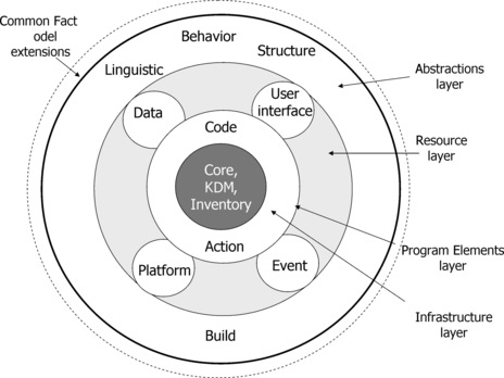
The common vocabulary for system facts, defined by the Knowledge Discovery Metamodel, consists of 12 packages arranged into four layers (represented as concentric circles in Figure 1). Most KDM packages define a language for one of the viewpoints. KDM implementations may choose individual packages for compliance.
 |
| Figure 1 KDM Layers |
11.2.1. Infrastructure layer
The KDM Infrastructure Layer consists of the Core, KDM, and Inventory packages, which provide a small common core for all other packages, define Inventory views of the artifacts of the system, and provide full traceability between the metamodel elements as links back to the artifacts (in software-intensive systems many of these links point to source code or binary code). The Core package defines a uniform extensibility mechanism, which is utilized to attach diverse attributes to the standard KDM entities, so that KDM becomes the foundation for the Common Fact Model, described in Chapter 9. KDM is defined as a metamodel that uses MOF, which defines the physical information exchange protocol for KDM using the OMG MOF to XML mapping. In addition, the KDM Core is aligned with the Resource Description Framework (RDF), which ensures that KDM can be efficiently mapped to RDF triples. Use of standard OMG technologies based on MOF allows a multitude of conforming physical representation for KDM facts. For example, one conforming implementation may define a set of Java classes to represent KDM facts in memory, and another implementation may choose to store KDM facts in an RDF triple-store, such as OpenRDF or Oracle. Both implementations can interoperate by exchanging standard KDM XML files built according to the KDM XML schema, defined in the KDM specification.
11.2.2. Program elements layer
The Program Elements Layer consists of the Code and Action packages.
• The Code package represents programming elements as determined by programming languages—for example data types, procedures, classes, methods, and variables. The KDM Code package provides greater level of detail and is seamlessly integrated with the architecturally significant views of the software system. Representation of datatypes in KDM is aligned with ISO standard ISO/IEC 11404:2007 General-Purpose Datatypes.
• The Action package addresses the low-level behavior elements of applications, including detailed control and data flow between statements. Code and Action package in combination provide a high-fidelity vocabulary for representing and exchanging facts determined by the programming languages, with emphasis on precise control- and data-flow facts, as they are determined by code.
11.2.3. Resource layer
The Resource Layer represents the operational environment of the existing software system as it is determined by the runtime platform.
The UI package represents the knowledge related to the user interfaces of the existing software system. Elements of the user interface are important endpoints for the end-to-end scenarios that flow through the system.
The Data package represents the artifacts related to persistent data, such as indexed files, relational databases, and other kinds of data storage. These artifacts are key to enterprise software as they represent the enterprise metadata. The KDM Data package is aligned with another OMG specification, called Common Warehouse Metamodel (CWM).
The Platform package represents the operating environment of the software, related to the operating system, middleware, and the like, including the control flows between components as they are determined by the runtime platform, such as callbacks and interprocess communication. The Platform package also includes the vocabulary for describing network nodes and the allocation of software components to network nodes. This network view of a system is important for system assurance.
The Event package represents the knowledge related to events and state-transition behavior of the existing software system. These facts complement control and data flows defined in the application code in situations when the software system uses dynamic state machine management code, and when some of the control flow is available as state-transition handlers that are dispatched by the state machine manager. Representing these facts is critical for establishing end-to-end scenarios, as they are defined by code and supported by the runtime platform.
11.2.4. Abstractions layer
The Abstraction Layer is a gateway into the Common Fact Model, described in Chapter 9. The purpose of this layer is to support the Integrated System Model for the entire duration of the system assurance project by supporting fact-oriented integration with other vocabularies identified for the OMG Assurance Ecosystem, such as the system architecture vocabulary described in Chapter 4, the threats and risks vocabulary described in Chapter 5 and the specific vocabulary of the system of interest. The mechanism of the Abstraction Layer supports identification of an object, for example, a particular asset of the system of interest, which can be done either externally or by mining the underlying KDM facts, entering the object as an element of the Integrated System Model, and establishing horizontal links to related objects and the vertical traceability links to the underlying KDM objects.
The Conceptual package consists of Linguistic and Behavior viewpoints as follows:
• Linguistic Viewpoint represents business domain knowledge and business rules. These facts can be mined from the underlying KDM facts, or identified externally, imported into the KDM repository of facts, and integrated with the underlying KDM facts by re-creating the vertical traceability links. The linguistic part is aligned with the Common Fact Model, described in Chapter 9 and the OMG Semantics of Business Vocabulary and Business Rules (SBVR) specification, [SBVR] described in Chapter 10.
• Behavior Viewpoint represents operational and system functions. These facts can be mined from the underlying KDM facts, or identified externally, imported into the KDM repository of facts, and integrated with the underlying KDM facts by re-creating the vertical traceability links. The input to the behavior facts are some of the operational and system views described in Chapter 4.
The Structure package describes the vocabulary for representing the logical organization of the software system into subsystems, layers, and components. These facts can be mined from the underlying KDM facts, or identified externally, imported into the KDM repository of facts, and integrated with the underlying KDM facts by re-creating the vertical traceability links.
The Build package represents the integration and supply chain views of the software system.
11.3. The Process of Discovering System Facts
KDM provides the foundation for the Integrated System Model. The high-level overview of the activities involved in establishing this model is provided in the description of the system assurance process in Chapter 3. In particular:
• Activity 2.3: Establish system model of the Project Preparation phase of the system assurance project focuses at establishing the so-called baseline system model.
• Activity 4.1: Discover system facts of the Architecture Security Analysis phase enhances the baseline model with the architecture facts about the system components, their functions, system entry points, security policy of the system, as well as the specific vocabulary of the system as described in Chapter 4.
• Activity 4.2: Identify threats of the Architecture Security Analysis phase enhances the integrated system model with the facts from the cybersecurity vocabulary related to threats described in Chapter 5 (assets, injuries, threat events, threats, risk measures, etc.).
• Activity 4.3: Identify safeguards of the Architecture Security Analysis phase enhances the integrated system model with the facts from the cybersecurity vocabulary related to safeguards (their identity, category, location within the system, and relation to threats that they mitigate). Safeguards were briefly discussed in Chapter 5.
• Activity 4.4: Detect vulnerabilities of the Architecture Security Analysis phase enhances the integrated system model with the facts from the cybersecurity vocabulary related to detected vulnerabilities as described in Chapters 6 and 7.
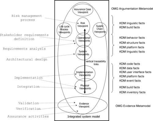
As a result of these activities, the integrated system model of the system of interest contains the facts corresponding to all relevant system assurance viewpoints, interconnected with vertical traceability links as well as horizontal relationships, including relationships across different vocabularies. This is illustrated in Figure 2. Traceability links are one of the key mechanisms of the KDM protocol. Their major benefit is that they enable integration between high-level system facts, such as the systems and operational views, risk views, supply chain views, and life-cycle processes views with the high-fidelity facts extracted directly from various machine-readable artifacts of the implementation of the system (including source and binary files of the applications, network configuration, runtime platform configuration, and database descriptions). Details of the fact-oriented integration and vertical traceability links were provided in Chapter 9.
 |
| Figure 2 Integrated System Model |
The system assurance case developed during Phase 3 of the system assurance process is also integrated with the system model. Other phases of the system assurance process, described in Chapter 3, analyze the integrated system model and gather evidence in support of the claims of the assurance case.
The process of building the baseline system model starts with the physical views defined by the KDM Inventory and Build viewpoints. The initial models are analyzed to understand the details of the programming languages and machine code formats used, the runtime platform used, and so on. At this point the proper KDM extractor tools for implementing the system of interest must be acquired. The process of building the baseline model continues by applying the KDM extractor tools to produce KDM code facts from the code of various applications; the user interface facts; the data facts related to the organization of persistent data; the platform facts related to the network configuration and deployment; and the facts related to the use of runtime resources and interprocess communications. This phase usually involves several iterations. Usually the KDM code facts are extracted first and then they are used as one of the inputs for extracting the user interface, data, platform, and event facts, because resource management supported by the runtime platform is controlled through the application programming interfaces (APIs) used in the code. From the perspective of the code, these API calls look like calls to library functions; while the resource views link these API calls to the KDM elements that represent specific resources, dynamically managed by the runtime platform.
Extraction of the physical and implementation views is a bottom-up process (see Figure 2). However, the process of enhancing the baseline system model with high-level facts, corresponding to systems and operational viewpoints, risk viewpoints, supply chain viewpoints, and process viewpoints, can be top-down, bottom-up, or any combination. The particular arrangement depends on how the system assurance process is integrated into the overall system life cycle and on the availability of high-fidelity machine-readable content to import into the system model.
Ideal integration of system assurance into the system life cycle and utilization of modeling techniques for system engineering enable the top-down process of completing the integrated system model by importing systems and operational views from the existing architecture repository, as well as importing the risk facts from the existing risk management system. When the machine-readable artifacts are not available, they can be entered manually from existing documentation and integrated with the baseline system model. However, when the artifacts are not available—for example, when a third-party security evaluation is performed during the transition into operation—the corresponding facts are identified during the security evaluation project bottom-up using the baseline system model.
The rest of this chapter provides a brief description into each KDM viewpoint as they are utilized in the System Assurance process.
11.4. Discovering the Baseline System Facts
11.4.1. Inventory views
The very first step in building the baseline system model is to enumerate the available artifacts. The Inventory package defines a set of noun and verb concepts whose purpose is to represent the physical artifacts of the existing system, such as source files, images, configuration files, and resource descriptions. The Inventory view of the system of interest contains the corresponding objects and facts. The inventory facts also include traceability links between other KDM elements and the regions of source and binary code; this is used to link a logical view of a module to the corresponding physical file.
The nature of the “source code” represented by a particular KDM inventory element is indicated by the “language” attribute and is not specified as part of the KDM vocabulary. Thus, when several years from now some system of interest involves a source file “foo.bas” in a language called visual basic 2020, the KDM Inventory view will represent this artifact as something like: <SourceFile id=”sf0056” name=”foo.bas” language=”visual basic 2020”/>. On the other hand, in order to extract the program element facts corresponding to the logical organization of the file “foo.bas,” the KDM extractor for the “visual basic 2020” must be acquired. These considerations position the Inventory view extractor at the initial phase of the fact gathering process. The Inventory view is investigated to determine the need for additional extractors. The Inventory view is utilized to calculate the metrics related to the effort of the system evaluation project. The artifacts are one of the well-known “locations” in the system, to which other facts can be linked. For example, vulnerabilities detected by a static analysis tools are often linked to a particular source file.
The Inventory package defines an Inventory viewpoint. It is determined by the entire software development environment of the existing software system. This viewpoint is defined as follows:
Concerns
• What are the artifacts (software items) of the system?
• What is the general role of each artifact (for example, is it a source file, a binary file, an executable, or a configuration description)?
• What is the organization of the artifacts (into directories and projects)?
• What are the dependencies between the artifacts?
Analytic methods
The Inventory viewpoint supports the following kinds of analysis:
• What artifacts depend on the given artifact?
• What are all unique programming languages used by the system?
• Are there any identifiable third-party components in the system? This analysis is based on the known signatures of the third-party packages, such as the open-source components, the header files for the third-party libraries, and APIs.
• What runtime platform elements are used by the system?
• What are the key measurements, related to the estimated effort, such as the total count of source files, the total count of the lines of code, and the distribution of the lines of code per each unique programming language used?
The Inventory views in combination with other KDM views support analysis to determine the original artifacts that correspond to a given KDM element providing the vertical traceability links all the way down to the regions of the source code.
Construction methods
• Inventory views are usually constructed by directory scanning tools, which identify files and their types.
• Construction of an Inventory view is determined by the particular development and deployment environments of the existing software system.
• Construction of an Inventory view is determined by the semantics of the environment as well as the semantics of the corresponding artifacts, and it is based on the mapping from the given development environment to KDM. In particular, the Inventory view extractor tool may use the “fingerprints” of the known programming languages to guess the file type.
Inventory views provide the foundation for the initial investigation of the system of interest and for building the baseline system model. Later in the process of enhancing the integrated system model, KDM Inventory views are used as standard locations to integrate various pieces of assurance information from non-KDM vocabularies, especially metrics and vulnerability findings from third-party vulnerability detection tools as described in Chapters 6 and 7.
11.4.1.1. Inventory viewpoint vocabulary in SBVR
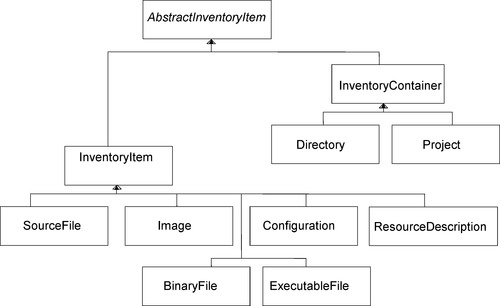
This section describes the concepts of the KDM Inventory viewpoint vocabulary. Several definitions in SBVR Structured English are included to demonstrate how KDM vocabulary is defined as a vocabulary in SBVR [SBVR]. Figure 3 illustrates the noun concepts of the KDM Inventory viewpoint. The six InventoryItem elements—SourceFile, ExecutableFile, BinaryFile, Image, Configuration, and ResourceDescription—are the common elements selected in KDM to describe software artifacts. Directory and Project elements provide a hierarchical organization to lists of software artifacts.
| Inventory View |
| Definition:A KDM view that represents facts about the physical artifacts of the existing software system |
| Source:based on Knowledge Discovery Metamodel 1.2 (11.3.1) [‘InventoryModel’] |
| General concept:KDM view |
| Reference schema:id of KDM view |
| Source File |
| Definition:a text file that contains instructions in a programming language |
| Source:based on Knowledge Discovery Metamodel 1.2 (11.3.5) [‘Source File’] |
| General concept:Inventory Item |
| Reference schema:id of KDM Entity |
| Source FilehasLanguage |
| Definition:the programming language that determines the logical organization of the source file. |
| Reference schema:Language of Source File |
| Source Filehasencoding |
| Definition:the encoding that determines the interpretation of the source file. |
| Reference schema:Encoding of Source File |
 |
| Figure 3 The noun concepts of the KDM Inventory viewpoint |
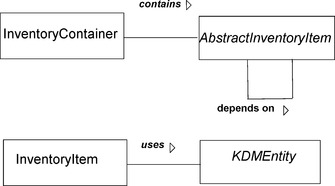
Figure 4 represents the verb concepts of the KDM Inventory viewpoint.
| Abstract Inventory Element1depends onAbstract Inventory Element2 |
| Definition:the constraint of an inventory. |
| Source:based on Knowledge Discovery Metamodel 1.2 (11.5.1) [‘DependsOn’] |
| Concept type:Abstract Inventory Relationship |
| Reference schema:id of a KDM Relationship |
| Inventory ContainercontainsInventory Element |
| Definition:describes a hierarchy of inventory elements |
| Concept type:KDM built-in Relationship |
| Reference schema:Inventory Element of Inventory Container |
| Inventory ElementusesKDM Entity |
| Definition:an underspecified relationship between a inventory element and a KDM Entity and that can be further extended through stereotyping |
| Source:based on Knowledge Discovery Metamodel 1.2 (11.8.2) [‘InventoryRelationship’] |
| Concept type:Abstract Inventory Relationship |
| Reference schema:id of a KDM Relationship |
 |
| Figure 4 The verb concepts of the KDM Inventory viewpoint |
11.4.2. Build views
The second step in building the baseline system model is to understand the role of the artifacts in the system. The artifacts are enumerated earlier as part of the Inventory Views. The Build view establishes the links between artifacts according to their role in the system life cycle. The process of identifying these relationships starts from the physical build instructions for the system (for example, make files, deployment scripts). The KDM Build package defines noun and verb concepts that represent the common vocabulary of facts involved in the build process of the given software system (including but not limited to the engineering transformations of the “source code” to “executables”). However, this process continues to consider the system architecture information, involving other life-cycle processes and enabling system and supply chain concerns. These concerns cannot be automatically discovered from the system artifacts, but need to be identified and added to the integrated system model, determined by the scope of the system assurance project.
The Build viewpoint is defined by the following considerations:
Concerns
• What are the inputs to the build process?
• What artifacts are generated during the build process?
• What tools are used to perform build steps?
• What is the workflow of the build process?
• Who are the suppliers of the source artifacts?
Analytic methods
• Supply chain analysis (what are the artifacts that depend on a given supplier?)
Construction methods
• Build views are initially constructed by analyzing build scripts and build configuration files for the given system. These inputs are specific to the development environment of the system of interest. The Build extractor tool uses knowledge of the semantics of the build environment to produce one or more Build views as output.
• Construction of the Build view is determined by the semantics of the build environment, and it is based on the mapping from the given build environment to KDM. Such mapping is specific only to the build environment (for example, the format of the build configuration files, etc.) and not to a specific software system.
Build views are used in combination with Inventory views to establish the baseline system model. Later in the process of enhancing the integrated system model, KDM Build views are used as standard locations to integrate various pieces of assurance information from non-KDM vocabularies, especially the information related to life-cycle processes and the supply chain.
Figure 5 illustrates the noun concepts of the Build viewpoint vocabulary.
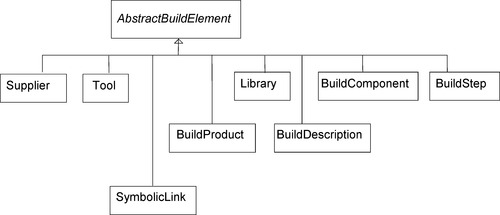 |
| Figure 5 The noun concepts of the Build viewpoint |
Figure 6 illustrates the verb concepts of the Build viewpoint. The build process is described as the graph of transformation steps, represented by BuildStep elements that consume build elements and produce build elements, such as Library, BuildComponent, and BuildProduct. These three elements are containers for various other KDM elements, in particular the elements of the Inventory model. The hierarchy is created through the “is implemented by” relationship from BuildComponent, and so forth, to the elements that are considered an implementation of the BuildComponent.
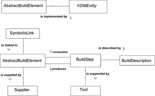 |
| Figure 6 The verb concepts of the Build viewpoint |
11.4.3. Data views
The KDM Data package defines a set of noun and verb concepts to describe the organization of persistent data in software systems. Facts in the Data viewpoint are usually determined by Data Description Languages (for example, SQL) but may in some cases be determined by the code elements. KDM Data views use the elements of the Code package related to simple datatypes. KDM Data views describe organizations of complex data repositories, such as record files, relational databases, structured data stream, XML schema, and XML documents.
The KDM Data viewpoint is defined by the following considerations:
Concerns
• What is the organization of persistent data in the software system?
• What are the information models supported by the software system?
• What are the consumers of persistent data?
• What are the producers of persistent data?
• What are the events corresponding to persistent data?
• Together with the Program Element and Platform views, what are the critical scenarios in the system that involve persistent data as source or as target?
• Together with other views, what is the sensitivity of the individual persistent data items?
• Together with other views, what are the information assets of the system and how do they map to physical data?
• Together with other views, what are the threats to information assets?
Analytic methods
The Data architectural viewpoint supports the following kinds of analysis:
• Data aggregation (the set of data items accessible from the given ColumnSet by adding data items through foreign key relationships to other tables).
Construction methods
• Data views are usually constructed by analyzing Data Definition Language artifacts for the given data management platform. The Data extractor tool uses knowledge of the data management platform to produce one or more Data views as output.
• As an alternative, for some languages like Cobol, in which some elements of the Data are explicitly defined by the language, the Data views are produced by compiler-like tools that take artifacts of the system as the input and produce one or more Data views as output (together with the corresponding Code views).
• Construction of the Data view is determined by the semantics of the data management platform and is based on mapping from the given data management platform to KDM. Such mapping is specific only to the data management platform and not to a specific software system.
Data views are used in combination with Code views and Inventory views. Later in the process of enhancing the integrated system model, KDM Data views are used as standard locations to integrate various pieces of assurance information from non-KDM vocabularies, especially information related to information assets and their sensitivity.
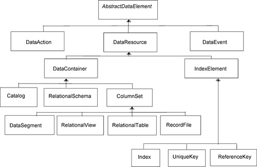
Figure 7 illustrates the noun concepts of the KDM Data viewpoint vocabulary.
 |
| Figure 7 Noun concepts of the Data viewpoint |
Catalog, RelationalSchema, and ColumnSet elements are containers for data elements; RelationalSchema may also contain CodeItem (for example, to represent stored procedures); and ColumnSet may contain ItemUnit (to represent database fields). All elements may contain DataEvent and DataAction elements, to represent specific behaviors associated with persistent data operations. Various IndexElements define another hierarchy on top of ItemUnit, using the “is implemented by” relation, to represent how groups of fields contribute to private and foreign keys and indices of the database. ‘References’ relationship is the link between a foreign key and the corresponding primary key. The passive verbs that define the structural relationship of Data views are illustrated in Figure 8.
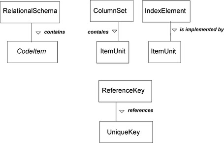 |
| Figure 8 The passive verbs of the Data viewpoint |
Figure 9 illustrates the active verbs of the Data viewpoint, which are part of the common vocabulary supporting analysis of system functions and behaviors. DataActions are units of behavior associated with DataResource elements. Why is it important? Persistent data management systems determine some of the control and data flow for the application through various mechanisms such as callbacks, exceptions, and implicit assignments to variables. For the end-to-end analysis of the system of interest, all control- and data-flow facts must be accounted for, and assurance evidence regarding the soundness of the analysis must be collected. DataActions and DataEvents provide the common vocabulary and mechanism for the knowledge extractor tools to adequately represent the semantics of the runtime platform of the system of interest. Further explanations are provided later in this chapter, in the section dedicated to the KDM Platform viewpoint.
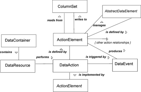 |
| Figure 9 The active verbs of the Data viewpoint |
Figure 10 illustrates a fragment of a KDM Data view. The left side of the picture shows two relational tables and a fragment of the corresponding description in SQL. The right side of the picture shows the key KDM facts involved in describing these tables, and the verbalization of these facts in Structured English using the noun and verb concepts of the Data viewpoint.
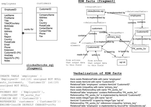 |
| Figure 10 Example of the KDM Data view |
The next diagram, Figure 11, illustrates the Data view at a lower (less detailed) resolution. The view shows a tool-generated KDM view, where each node is a RelationshipTable element. These elements show the 12 tables of the Clicks2Bricks relational schema (this is a system described as the case study in Chapter 12). Dependencies between data elements are the so-called KDM aggregated relationships. They summarize all data facts that involve a pair of relational tables. The nodes named “ENV:SRC” and “ENV:SNK” represent the rest of the system (any elements that are not in the current view). These nodes are the endpoints for the aggregated relationships that summarize the uses of the 12 main elements of the view by the rest of the system (relationships from the ENV:SRC node) and how these elements use the rest of the system (relationships to the ENV:SNK node). Relationships between tables are determined by the foreign keys from one table to another. Uses of relational tables are determined by the data actions and the use of relational data in the application code, for example, SQL SELECT statements.
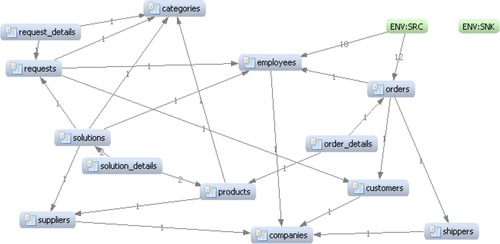 |
| Figure 11 KDM Data view at a less detailed level of resolution |
11.4.4. UI views
The KDM UI package defines a set of noun and verb concepts that represent the elements of user interfaces, such as screens, reports, and their fields; their composition, sequence of operations, and, of course, their relationships to the other elements of the systems. User interfaces are notorious for involving a tremendous amount of detailed attributes related to color, positions of the elements, and various minute properties affecting the behavior and appearance of the graphical widgets. These details are highly specific to a particular graphical framework, such as the Java AWT, Microsoft Windows, and the X windows. The KDM common vocabulary for the user interface includes a very small number of terms because KDM focuses on the user interfaces only as the conceptual endpoints for various end-to-end scenarios and functionality of the system of interest. The KDM User Interface viewpoint is defined by the following considerations:
Concerns
• What are the distinct elements of the user interface of the systems?
• What is the organization of the user interface?
• How does the user interface use artifacts of the system (for example, images)?
• What data flows originate from the user interface?
• What data flows output to the user interface?
• What control flows are initiated by the user interface events?
Analytic methods
The UI architectural viewpoint supports the following kinds of analysis:
• Data flow (for example, what scenarios read from a given UI element; what scenarios write to a given UI element; what scenarios manage a given UI element?)
• Control flow (for example, what action elements are triggered by events in a given UI element; what scenarios operate on a given UI element?)
• Workflow (for example, what UI elements will be displayed after the given one; what UI elements are displayed before the given one?)
Construction methods
• UI views are usually constructed by analyzing Code views for the given system as well as the UI-specific configuration artifacts. The UI extractor tool uses knowledge of the API and semantics for the given runtime platform to produce one or more UI views as output.
• As an alternative, for some languages like Cobol, in which the elements of the UI are explicitly defined by the language, the UI views are produced by the parser-like tools that take artifacts of the system as the input and produce one or more UI views as output (together with the corresponding Code views).
• Construction of the UI view is determined by the semantics of the UI platform, and it is based on mapping from the given UI platform to KDM. Such mapping is specific only to the UI platform and not to a specific software system.
• UI views are used in combination with Code views and Inventory views. During the Architecture Security Analysis phase, KDM UI views enable understanding of the functionality of the system of interest.
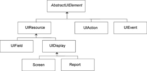
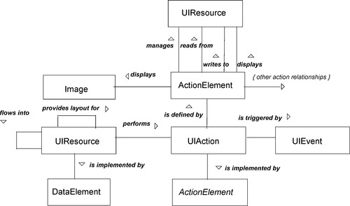
Figure 12 illustrates the noun concepts of the UI viewpoint. UIResource elements Screen and Report are containers for UIField elements. The corresponding “contains” relationship determines the structure of the UI views. In addition UIResource elements can contain UIAction and UIEvent elements to represent control and data flows determined by the UI part of the runtime platform. This is further explained in the section dedicated to the Platform views.
 |
| Figure 12 The noun concepts of the UI viewpoint |
Figure 13 illustrates the verb concepts of the UI viewpoint. Specific relationships between UI elements are “UIResource flows into UIResource” and “UIResource provides layout for UIResource.” Other verb concepts describe control and data flows between code and the elements of the user interface.
 |
| Figure 13 The verb concepts of the UI viewpoint |
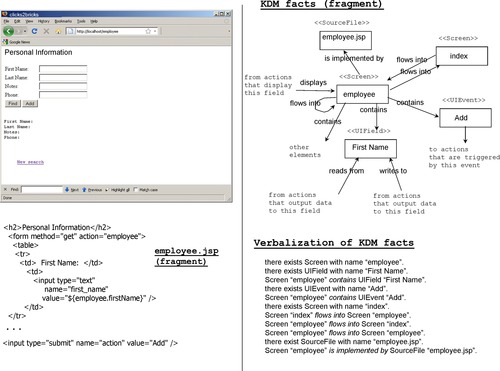
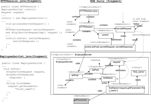
Figure 14 illustrates the KDM UI views. The left side of the picture shows a typical Web page with fields and buttons and a fragment of its description in Java Server Pages (JSP). The right side shows the key elements of the corresponding KDM UI view and the verbalization of the KDM facts in SBVR Structured English using the noun and verb concepts of the KDM UI common vocabulary.
 |
| Figure 14 Example of the KDM UI view |
11.4.5. Code views
The Code viewpoint defines a large set of elements whose purpose is to provide a language-independent vocabulary for various constructs determined by common programming languages. The Code viewpoint is defined by the following considerations:
Concerns
• What are the computational elements of the system?
• What are the modules of the system?
• What is the organization of the computational elements?
• What are the datatypes used by the computational elements?
• What are the elementary units of behavior of the system?
• What are the relationships between the code elements? In particular what are the control-flow and data-flow relationships?
• What are the important noncomputational elements?
• How are computational elements and modules related to the physical artifacts of the system?
Analytic methods
The Code viewpoint supports the following main kinds of analysis:
• Composition (for example, what code elements are owned by a CompilationUnit, SharedUnit, or a CodeAssembly; what action elements are owned by a CallableUnit?)
• Data flow (for example, what action elements read from a given StorableUnit; what action elements write to a given StorableUnit; what action elements create dynamic instances of a given Datatype; what action elements address a particular StorableUnit; what data elements are being read as actual parameters in a call?)
• Control flow (for example, what CallableUnit is used in a call; what action element is executed after the given action element; what action elements are executed before the given action element; what data element is used to dispatch control flow from a given action element; what action element is executed after the given element under what conditions; what is the exceptional flow of control; what action elements are executed as entry points to a given module or a CallableUnit?)
• Datatypes (for example, what is the datatype of the given storable unit; what is the base datatype of the given pointer type; what is the base datatype of the given element of the record type; what is the signature of the given CallableUnit?)
• Analysis of the interfaces, templates, and pre-processor. All relationships defined in the Code model are nontransitive. Additional computations are required to derive, for example, all action elements that can be executed after the given action element, or all CallableUnits that a given action element can dispatch control to.
The KDM mechanism of aggregated relationship is used to derive relationships between KDM elements that own or reference various Code elements (usually, Module and CodeAssembly) based on the low-level relationship between individual Code elements.
Construction methods
• Code views that correspond to the KDM Code viewpoint are usually constructed by parser-like tools that take artifacts of the system as the input and produce one or more Code views as output.
• Construction of the Code view is determined by the syntax and semantics of the programming language of the corresponding artifact, and it is based on the mapping from the given programming language to KDM. Such mapping is specific only to the programming language and not to a specific software system.
• The mapping from a particular programming language to KDM may produce additional information (system-specific, programming language-specific, or extractor tool-specific). This information can be attached to KDM elements using stereotypes, attributes, or annotations.
11.4.5.1. Code views: elements of structure
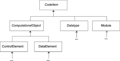
The Code package defines the so-called code item elements—the named elements determined by the programming language, the so-called symbols, definitions, and so on—and structural relations between them. Code items are further categorized into ComputationalObject, Datatypes, and Modules. The Action package defines behavioral elements and various behavioral relationships, which determine the control and data flows between code items.
Description of the Code viewpoint is further subdivided into the following parts:
• Code Elements representing Modules
• Code Elements representing Computational Objects
• Code Elements representing Datatypes
• Code Elements representing Preprocessor Directives
• Miscellaneous Code Elements
Data representation of KDM is aligned with the International Standard ISO/IEC 11404:2007 (General-Purpose Datatypes). In particular, KDM provides distinct metamodel elements for “data elements” (for example, global and local variables, constants, record fields, parameters, class members, array items, and pointer base elements) and “datatypes.” Each data element has a property “type” that links the data element to its corresponding datatype element. KDM distinguishes primitive datatypes (for example, Integer, Boolean), complex user-defined datatypes (for example, array, pointer, sequence), and named datatypes (for example, a class, a synonym type). KDM metamodel elements corresponding to datatypes are subclasses of a generic class Datatype. KDM metamodel elements corresponding to data elements are subclasses of a generic class DataElement.
KDM code elements represent existing artifacts determined by a programming language. KDM elements provide sufficient coverage for most common datatypes and data elements, common to the mainstream programming languages. KDM also provides several powerful generic extensible elements that can be further used with stereotypes to represent uncommon situations.
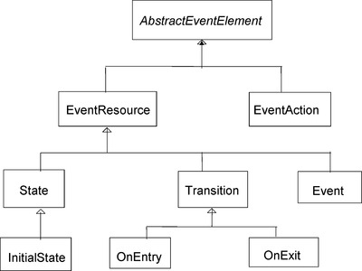
The taxonomy of the noun concepts of the Code viewpoint is illustrated in Figure 15.
 |
| Figure 15 The taxonomy of the noun concepts of the KDM Code viewpoint |
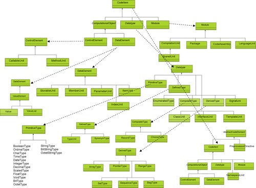
The next diagram, Figure 16, illustrates the entire organization of the KDM Code viewpoint. Most of the top-level elements are decomposed into another level, with the exception of the Datatype element, which contributes to over the half of the number of elements in the KDM Code vocabulary.
 |
| Figure 16 Complete taxonomy of the noun concepts of the Code viewpoint |
Figure 17 illustrates the verb concepts of the KDM Code viewpoint. The verb concept “CodeItem is typed by Datatype” describes relationships between the Code items and Datatypes. The “Datatype extends Datatype” relationship represents subtyping relationships between the Datatypes of the system of interest.
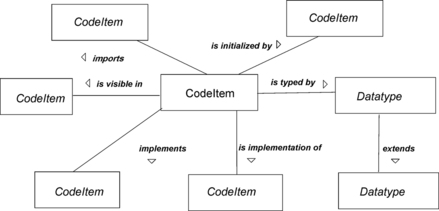 |
| Figure 17 The verb concepts of the KDM Code viewpoint |
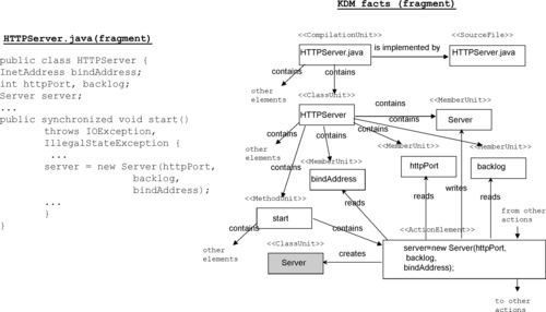
Figure 18 illustrates the Code view: The left side of the picture shows a code fragment (in Java). In the middle of the picture is the decomposition of the code example according to the constructs defined by the Java language. Above each element is guidance for the mapping into KDM. Thus, the element s1 that corresponds to the Java file with the name “Main.java” is mapped to the KDM CompilationUnit element. Figure 18 also illustrates several relationships that are implicit in the code fragment (elements e1-e4). The right side of the picture shows a small fragment of the KDM code view.
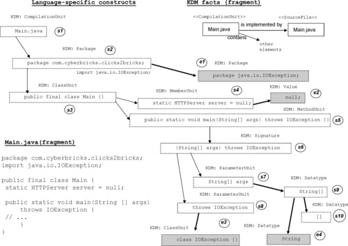 |
| Figure 18 Example of the KDM Code view |
11.4.5.2. Code views: elements of behavior
The Action package defines the elements of behavior—the statements and various control- and data-flow relationships between statements and code items. Figure 19 illustrates the noun concepts from the common vocabulary of behavior elements of the Code viewpoint. The key element is ActionElement. It represents a statement in the application code (sometimes a collection of statements or a part of the original statement). A BlockUnit represents blocks of statements in the original application code.
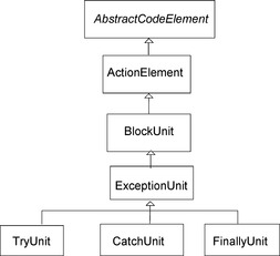 |
| Figure 19 The noun concepts of the Code viewpoint: actions |
The next diagram, Figure 20, illustrates the verb concepts that describe the elementary data-flow relationships within the application code. The corresponding facts are illustrated in Figure 21, using an example code fragment.
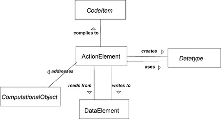 |
| Figure 20 The verb concepts of the Code viewpoint: data flow |
 |
| Figure 21 Example of the data-flow facts of the KDM Code views |
The next two diagrams, Figures 22 and 23, illustrate the elementary control flow relations.
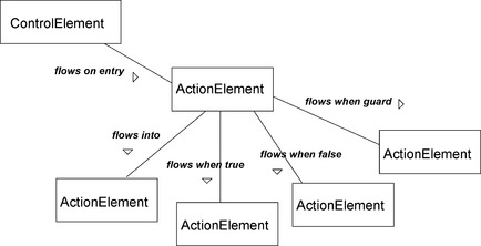 |
| Figure 22 The verb concepts of the Code view: control flow |
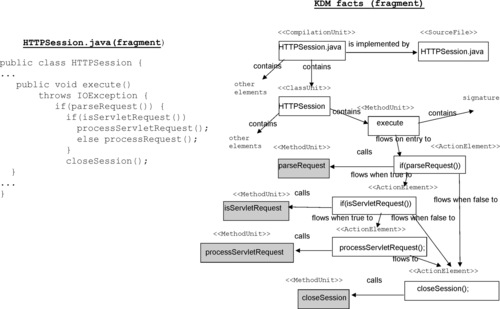 |
| Figure 23 Example of the control flow facts of the KDM Code views |
The next two diagrams, Figures 24 and 25, illustrate the call relationships.
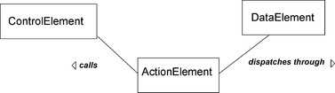 |
| Figure 24 Verb concepts of the Code viewpoint: calls |
 |
| Figure 25 Example of call facts of the KDM Code views |
Figure 26 illustrates the Code facts at a less granular level of resolution. The picture shows a tool-generated view, where six nodes represent classes of the Clicks2Bricks application and the last node represents a Java package “servlet.” Relationships between nodes are the KDM aggregated relationships that summarize all facts existing between each pair of nodes, including the two ENV nodes that represent the rest of the system.
 |
| Figure 26 KDM Code view at a less detailed level of resolution |
11.4.5.3. Micro KDM
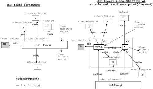
The KDM specification defines a separate compliance point for each viewpoint. The ordinary compliance point for the Code viewpoint does not specify the granularity of ActionElement. It is the responsibility of the supplier of the knowledge extractor tool to select appropriate resolution. Usually this decision is made based on the level of resolution of the existing proprietary representation. Regardless of the selected resolution the resulting KDM views are useful for architecture evaluation because they support fact-based integration, the vertical traceability links, and aggregated relations to the architecture significant levels, which are of lower resolution anyway. However, at the detailed level, the scope of the action element may lead to ambiguities in interpreting the precise semantics of the control and data flows. This is illustrated in the next picture (left side) in Figure 27, where one ActionElement represents a complex statement. The pattern of relationship is ambiguous.
 |
| Figure 27 Example of micro KDM action elements |
To support high-fidelity analysis (including full static analysis) of KDM views, the KDM specification defines an enhanced compliance point, which involves precise definitions of high-resolution ActionElements (called micro action). This compliance point is referred to as micro KDM. The specification of micro KDM actions essentially defines a “virtual machine” for KDM. The micro KDM representation of the same example is illustrated at the right side of Figure 27. The two micro actions involved are “Call” and “Add.”
Micro KDM actions are grouped into the following 11 categories (the total number of micro actions in each group is given in parentheses):
• Comparison actions, based on ISO 11404 (10)
• Operations on primitive numeric types, based on ISO 11404 (7)
• Bitwise operations on primitive datatypes, based on ISO 11404 (7)
• Control actions (13)
• Access to Derived Datatypes, based on ISO 11404 (13)
• Conversions between Datatypes (4)
• Operations on StringType, based on ISO 11404 (5)
• Operations on SetType, based on ISO 11404 (8)
• Operations on SequenceType, based on ISO 11404 (5)
• Operations on BagType, based on ISO 11404 (6)
• Resource actions (4)
11.4.6. Platform views
The Platform viewpoint defines a set of elements whose purpose is to represent the runtime operating environment of the system of interest. The application code is not self-contained, for it is determined not only by the selected programming languages, but also by the selected corresponding runtime platform. Platform elements determine the execution context of the application and contribute to the end-to-end control and data flows of the system. The elements of the Platform viewpoint provide the common vocabulary to address the following issues:
• Unique resources that the runtime platform manages on behalf of the applications.
• The key services provided by the platform, especially those that are related to managing resources. An application code calls platform services using an application programmer's interface (API) to manage the life cycle of a resource.
• Control flow between application components determined by the platform, including the interprocess communication, and error handling across application components.
Examples of Platform elements include UNIX OS File System, UNIX OS process management system, Windows 2000, OS/ 390, Java (J2SE), Perl language Runtime support, IBM CICS TS, IBM MQSeries, Jakarta Struts, BEA Tuxedo, CORBA, HTTP, TCP/IP, Eclipse, EJB, JMS, Database middleware, Java Servlets, and Java Threads.
The Platform viewpoint is defined by the following considerations:
Concerns
• What unique resources are used by the software system?
• What elements of the runtime platform are used by the software system?
• What behavior is associated with the resources of the runtime platform?
• What control flows are initiated by the events associated with the runtime resources?
• What control flows are initiated by the runtime environment?
• What are the bindings between the code and runtime environment?
• What are the deployment configurations of the software system?
• What are the dynamic/concurrent threads of activity within the software system?
Analytic methods
The Platform viewpoint supports the following kinds of analysis:
• Data flow (for example, what action elements read from a given resource; what action elements write to a given resource; what action elements manage a given resource; including indirect data flow using a MarshalledResource or a MessagingResource where a particular resource is used to perform a data flow between the “send” action element and the “receive” action element?)
• Control flow (for example, what action elements are triggered by events in a given resource; what action elements operate on a given resource?)
• Identify resource instances based on resource handles and their use in various modules.
Construction methods
• Platform views that correspond to the KDM Platform architectural viewpoint are usually constructed by analyzing Code views for the given system as well as the platform-specific configuration artifacts. The platform extractor tool uses knowledge of the API and semantics for the given runtime platform to produce one or more Platform views as output.
• As an alternative, for some languages such as Cobol, in which the elements of the runtime platform are explicitly defined by the language, the Platform views are produced by the parser-like tools that take artifacts of the system as the input and produce one or more Platform views as output (together with the corresponding Code views).
• Construction of the Platform view is determined by the semantics of the runtime platform and is based on mapping from the given runtime platform to KDM. Such mapping is specific only to the runtime platform and not to a specific software system.
Platform views are used in combination with Code views and Inventory views. The purpose of Platform views is to complete the control and data flows of the end-to-end system scenarios.
The next two diagrams, Figures 28 and 29, illustrate the noun and verb concepts of the KDM Platform viewpoint.
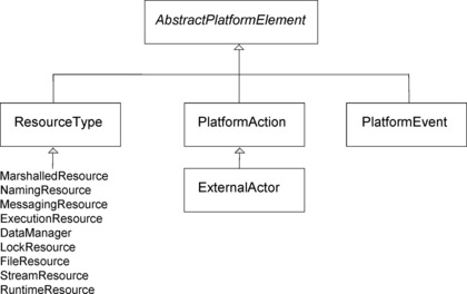 |
| Figure 28 The noun concepts of the Platform viewpoint |
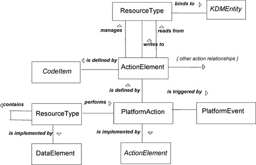 |
| Figure 29 The verb concepts of the Platform viewpoint: behavior |
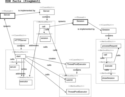
Figure 30Figure 31 and Figure 32 illustrate the behavior determined by the runtime platform and shows how KDM facts represent this behavior to ensure end-to-end control and data flows through applications with assurance of the soundness of the cause-and-effect analysis performed using the KDM views. Figure 30 illustrates three Java classes from the Clicks2Bricks system. The code uses the so-called ThreadPoolExecutor API of the standard Java runtime platform. The key relationships determined by this mechanism are illustrated next. Basically, the ThreadPoolExecutor object launches Java threads (using an internal pool of threads). The new thread executes method “call” of the class, submitted to the executor.
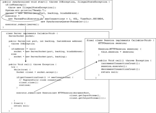 |
| Figure 30 Platform behavior in KDM Platform views: code example |
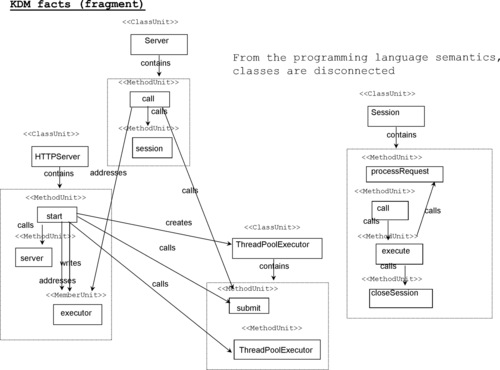 |
| Figure 31 Platform behavior: The KDM Code view is not enough |
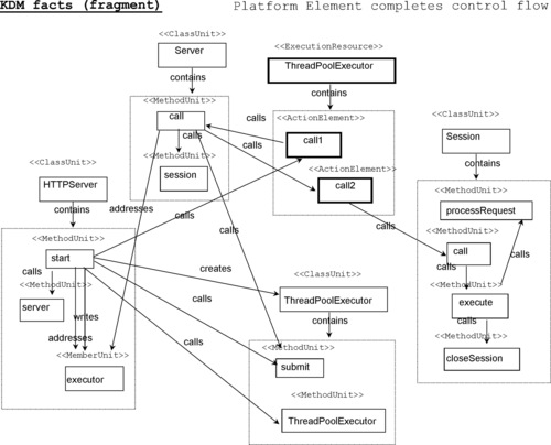 |
| Figure 32 Example of Platform behavior facts in KDM Platform view |
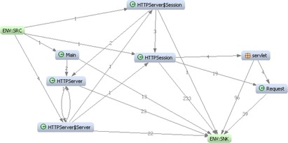
From the pure code perspective (determined by the Java language), however, there are no calls to the methods with name “call” in classes “Server” and “Session.” There are no relationships from the class HTTPServer to the class Server and from the class Server to the class Session. However, classes HTTPServer and Server have relationships to the methods of the class ThreatPoolExecutor. The code perspective does not show an end-to-end scenario of elementary control-flow relationships between classes HTTPServer, Server, and Session (see Figure 31). The knowledge that is required to have an end-to-end control and data flow in the system model is related to the semantics of the Java runtime platform, in particular the semantics of the ThreadPoolExecutor API.
Once the additional platform-specific knowledge is imported into the platform extractor tool, it can generate several facts that restore the end-to-end scenario. The new facts are illustrated at Figure 32. Note that now the combined KDM view (Code + Platform) shows an end-to-end scenario from the method “start” to method “Call” in “Server” class, to method “Call” in the class “Session,” to method “processRequest” in the class “Session”. This is the key functional scenario of the Clicsk2Bricks system. Note that the KDM facts in this example are aggregated to a less detailed level of resolution: Entire methods are shown as the sources of the “calls” relationships. However, the elementary “Calls” relationship is defined as having an ActionElement as the source.
The same mechanism of “platform actions” representing abstracted behavior of the system's runtime platform based on knowledge of the corresponding APIs is used in KDM Data, UI, and Event views. Additional actions can be associated with the DataResources, UIResources, and the elements of KDM state transition view to provide a high-fidelity representation of end-to-end control and data flows through the applications and through the entire system.
Figure 33 illustrates the noun concepts of the KDM Platform viewpoint describing the elements of deployment. The deployment views show how relationships between machine nodes on the network and the software components are deployed to these nodes. The verb concepts of Platform viewpoint are illustrated at Figure 34.
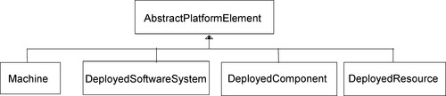 |
| Figure 33 The noun concepts of the Platform viewpoint: deployment |
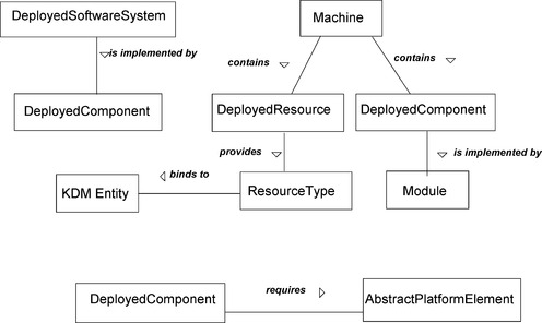 |
| Figure 34 The verb concepts of the Platform viewpoint: deployment |
The Machine element is a container for the DeployedResource and DeployedComponent elements allocated to the corresponding machine node. On the other hand, the DeployedSoftwareSystem element gathers the entire set of components of a single system. A single machine node may host components of different systems, so both groupings are needed.
Figure 35 illustrates the deployment configuration for the network diagram of the Clicks2Bricks system, provided in the concept of operations description in Chapter 12. The purpose of the deployment elements is to extend the set of “locations” in the system available for the analysis and integration with other non-KDM vocabularies.
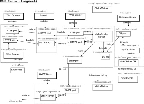 |
| Figure 35 Example of the KDM Platform view: deployment |
Figure 36 illustrates the additional noun and verb concepts related to concurrency in code. Knowledge of the API to the runtime platform is required to generate these views. However, once extracted, these facts are seamlessly integrated with other KDM facts.
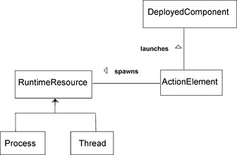 |
| Figure 36 The concepts of the Platform viewpoint: concurrency |
Figure 37 illustrates the KDM facts related to concurrency.
 |
| Figure 37 Example of the KDM Platform view: Concurrency |
11.4.7. Event views
The Event viewpoint defines a set of elements whose purpose is to represent the high-level behavior of systems in terms of event-driven state transitions. Elements of the KDM Event viewpoint represent states, transitions, and events. States can be concrete, for example, the ones that are explicitly supported by some state-machine-based runtime framework or a high-level programming language, such as CHILL, or can represent abstract states, for example, states corresponding to the operational or system views, or design states that are associated with a particular algorithm, resource, or a user interface.
The Event viewpoint is defined by the following considerations:
Concerns
• What are the distinct states involved in the behavior of the software system?
• What are the events that cause transitions between states?
• What action elements are executed in a given state?
Analytic methods
The Event architectural viewpoint supports the following main kinds of analysis:
• Reachability (for example, what states are reachable from the given state?)
• Control flow (for example, what action elements are triggered by a given state transition; what action elements will be executed for a given traversal of the state transition graph?)
• Data flow (for example, what data sequences correspond to a given traversal of the state transition graph?)
Construction methods
• Event views that correspond to the KDM Event architectural viewpoint are usually constructed by analyzing Code views for the given system as well as the configuration artifacts specific to the event-driven framework. The Event extractor tool uses knowledge of the API and semantics of the event-driven framework to produce one or more Event views as output.
• Construction of the Event view is determined by the semantics of the event-driven framework, and it is based on the mapping from the given event-driven framework to KDM. Such mapping is specific only to the event-driven framework and not to a specific software system.
Event Views are used in combination with Code views, Data views, Platform views, and Inventory views to represent high-fidelity facts related to complete control flows of the system of interest, especially ones related to the underlying runtime platform. During the Architecture Security Analysis phase, Event views are used in combination with the Behavior views to represent relevant system architecture views and establish vertical traceability links to the system facts at the implementation level. In this capacity the event entities are used as standard locations to integrate various pieces of assurance information from non-KDM vocabularies, especially the information related to functions of the system of interest.
The next two diagrams, Figures 38 and 39, illustrate the noun and verb concepts of the KDM Event viewpoint vocabulary. These elements are further illustrated at Figure 40 by showing example facts.
 |
| Figure 38 The noun concepts of the Event viewpoint |
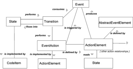 |
| Figure 39 The verb concepts of the Event viewpoint |
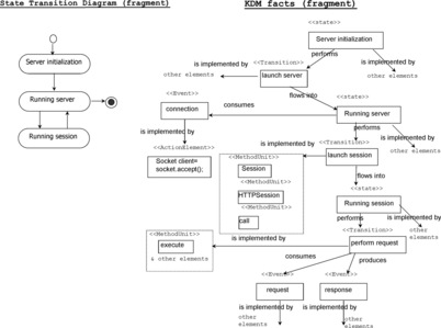 |
| Figure 40 Example facts of the KDM event views |
For example, the Clicks2Bricks Web server may have first go through an initialization, then enter a state in which it awaits a connection, and then spawn a session in which it processes the request and sends a message back. According to the viewpoint language of KDM event models, this example involves three entities of kind “state” (state “Server initialization,” state “Running server,” and state “Running session”), three entities of the kind event (events “Connection,” “Request,” and “Message”), and three transitions (initial transition to state “Server setup,” transition between states “Server setup” and “Running server,” and transition between states “Running server” and “Running session”).
11.5. Performing Architecture Analysis
11.5.1. Structure views
The Structure viewpoint defines several noun and verb concepts that represent architectural elements of the system of interest, such as subsystems, layers, and packages, and define the traceability of these elements to other KDM facts for the same system. The Structure viewpoint is defined by the following considerations:
Concerns
• What are the structural elements of the system, and what is the organization of these elements?
• What software elements compose the system?
• How are the structural elements of the system related to the computational elements?
• What are the connections of these elements based on the relationships between the corresponding computational elements?
• What are the interfaces of the structural elements of the system?
Analytic methods
The Structure architectural viewpoint supports the following kinds of analysis:
• Dependencies (are components properly connected?)
• Coupling and cohesion (the number of internal relationships within a component compared to the number of relationships to other components)
• Efferent and afferent relationship (uses of a component by other components and uses of other components by the given component)
• Interfaces (what is the required and provided interface of the given component?)
Construction methods
• Structure views that correspond to the KDM Structure architectural viewpoint are usually constructed by analyzing the architecture models of the given system. The Structure extractor tool uses knowledge of the architecture models to produce one or more Structure views as output.
• As an alternative, Structure views can be produced manually using the input from the architect of the system and architecture documentation.
• Construction of the Structure view is determined by the architectural description of the system.
• Construction of the Structure views corresponding to a particular architectural description may involve additional information (system-specific or architecture-specific). This information can be attached to KDM elements using stereotypes, attributes, or annotations.
The organization of the system may be presented as a single Structure view or as a set of multiple Structure views showing layers, components, subsystems, or packages. The reach of this representation extends from a uniform architecture to an entire family of module-sharing subsystems.
The Structure model owns a collection of StructuralElement instances.
Packages are the leaf elements of the Structure model, representing a division of a system's Code modules into discrete, nonoverlapping parts. An undifferentiated architecture is represented by a single Package.
The StructuralGroup recursively gathers StructuralElements to represent various architectural divisions. The Software System subclass provides a gathering point for all the system's packages directly or indirectly through other Structure elements. The packages may be further grouped into Subsystems, Layers, and Components, or Architecture views.
Structure views are used in combination with Code views, Data views, Platform views, UI views, and Inventory views. Structure elements are the main “locations” of the system of interest for the purpose on integrating various non-KDM vocabularies, in particular the operational and system views, threats, and risks.
Figures 41 and 42 illustrate the noun and verb concepts of the KDM Structure viewpoint.
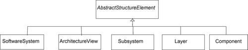 |
| Figure 41 The noun concepts of the Structure viewpoint |
| Figure 42 The verb concept of the Structure viewpoint |
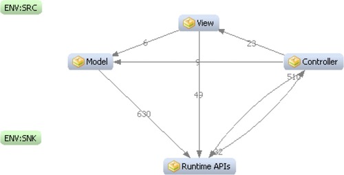
Relationships of the Structure views are entirely defined by the mechanism of aggregated relations. The only relationship defined in the Structure view established the vertical traceability links between the system elements (instances of the noun concepts of the Structure vocabulary) and other KDM elements. The next diagram, Figure 43, illustrates an architecture significant Structure view of the Clicks2Bricks system (from the case study that is described in Chapter 12).
 |
| Figure 43 Example of the Structure view at a less detailed level of resolution |
The view at Figure 43 maps the entire code base of the Clicks2Bricks into the elements of the Model-View-Controller architecture pattern. The facts in Figure 43 can be verbalized using the SBVR Structured English as follows:
There exists Subsystem with name “View.”
There exists Subsystem with name “Controller.”
There exists Subsystem with name “Model.”
Subsystem “View” depends on Subsystem “Model.”
Subsystem “View” depends on Subsystem “Runtime Paltform APIs.”
Subsystem “Model” depends on Subsystem “Runtime Paltform APIs.”
Subsystem “Controller” depends on Subsystem “View.”
Subsystem “Controller” depends on Subsystem “Model.”
Subsystem “View” depends on Subsystem “Runtime Paltform APIs.”
Figure 43 shows that Subsystems “Model,” “View,” “Controller,” and “Runtime Platform APIs” cover an entire set of system facts. This is based on the absence of relations to ENV nodes and from ENV nodes (to and from the rest of the system), as well as on the understanding that the KDM system model is a closed system that contains all known facts about the system of interest (within the scope of the model). Under these assumptions, the above view is evidence for the claim that the Subsystem “Model” depends only on the entities inside the subsystem “Runtime Platform APIs.”
11.5.2. Conceptual views
The Conceptual viewpoint defined in the KDM Conceptual package provides constructs for creating a linguistic and behavior models during the analysis phase of knowledge discovery from the existing code.
The Conceptual viewpoint is defined by the following considerations:
Concerns
• What domain concepts are implemented by the system?
• What are the behavior elements of the system?
• What business rules are implemented by the system?
• What scenarios are supported by the system?
Analytic methods
The Conceptual viewpoint supports the following main kinds of checking:
• Conceptual relationships (what are the relationships between conceptual entities, based on their implementation by the Code and Data entities?)
• Scenario flow (what are the control-flow relationships between the two scenarios based on the flow between action elements referenced by each scenario?)
• BehaviorUnit coupling (what are the control-flow and data-flow relationships between two behavior units based on the action elements referenced by each behavior unit?)
• Business Rule analysis (what is the logic of the business rule based on the action elements referenced by the business rule?)
Conceptual views are used in combination with Code views, Data views, Platform views, UI views, and Inventory views.
Construction methods
• Conceptual views can be produced manually using the input from the information analysis and the architect of the system and architecture documentation.
• Construction of the Conceptual view is determined by the domain model and the architectural description of the system.
• Construction of the Conceptual views corresponding to a particular architectural description may involve additional information (system-specific or architecture-specific). This information can be attached to KDM elements using stereotypes, attributes, or annotations.
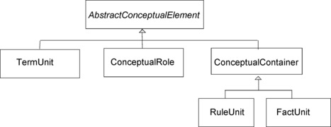
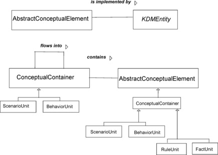
The Conceptual Model enables mapping of KDM compliant model to models compliant to other specifications. Currently, it provides “concept” classes—TermUnit and FactUnit facilitating the mapping to SBVR specification, described in Chapter 10.
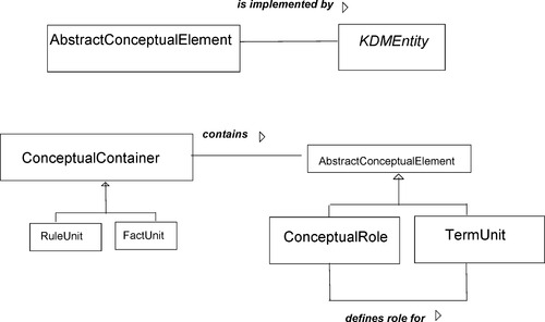
KDM TermUnit is a representation of the SBVR noun concept or SBVR individual concept as a first-class citizen on a KDM view. This element can be further connected to its implementation by lower-level KDM elements for the Code, Data, UI and Platform views by the vertical traceability links using the “is implemented by” relationships. This is the key to mechanism for using KDM as the nucleus of the Common Fact Model and importing the vocabularies, defined in 4, 5, 6 and 7 in a KDM-compliant tool for the purpose of establishing the integrated system model.
Similarly, a KDM FactUnit is a representation of the SBVR verb concept in the integrated fact model. KDM RuleUnit element is the representation of the SBVR elements of behavior guidance.
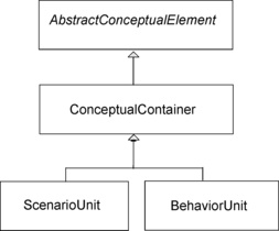
The Conceptual Model also provides “behavior” types—BehaviorUnit and ScenarioUnit that support mapping to various external models, including but not limited to activities/flow chart and swim lane diagrams, and use case scenarios. The following explains the difference between these “behavior” types:
• BehaviorUnit represents a behavior graph with several paths through the application logic and associated conditions. The “implementation” of this graph is provided by the ActionElements connected with Flow relations, from the Program Elements KDM layer. The graph can be as small as a single ActionElement. BehaviorUnit is an “abstraction” of ActionElements since it provides a modeling element for representing a collection of ActionElements that is meaningful from the application domain perspective, and further manipulates with this representation as a first-class citizen of the ConceptualModel of KDM.
• ScenarioUnit represents a path (or multiple related paths) through the behavior graph. For example, ScenarioUnit corresponds to a trace through the systems, or a “use case.” ScenarioUnit can own an entire collection of BehaviorUnits, connected with ConceptualFlow elements, and can thus represent a slice of the original behavior graph in implementing the software system. The conditions responsible for navigation between alternative paths within the graph can be represented as RuleUnits.
• RuleUnit represents a condition, a group of conditions, or a constraint. RuleUnit is a representation for some meaningful navigation conditions within behavior graphs represented by several BehaviorUnits.
11.5.2.1. Linguistic viewpoint
The purpose of Linguistic elements is to provide a bridge between low-level, physical, and implementation viewpoints and high-level policy documents describing the business rules of the system of interest. Also, systematic traceability from domain-specific vocabulary terms all the way down to the individual code elements provides an efficient way of navigating the system and allows assurance of certain evaluation activities.
Figure 44 illustrates the noun concepts of the KDM Linguistic viewpoint.
 |
| Figure 44 The noun concepts of the Linguistic viewpoint |
The next diagram, Figure 45, illustrates the verb concepts of the Linguistic viewpoint.
 |
| Figure 45 The verb concepts of the Linguistic viewpoint |
Figure 46 illustrates KDM linguistic facts for a fragment of the Conceptual Model for Clicks2Bricks system, described in more detail in Chapter 12.
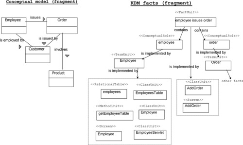 |
| Figure 46 Example of the KDM linguistic facts in the Conceptual view |
11.5.2.2. Behavior viewpoint
The purpose of Behavior elements is to provide a bridge between low-level, physical, and implementation viewpoints and high-level functional views of the system of interest. Also, systematic traceability from the system functions all the way down to the individual code elements provides an efficient way of navigating the system and allows assurance of certain evaluation activities.
The next two diagrams, Figures 47 and 48, illustrate the concepts of the KDM Behavior viewpoint.
 |
| Figure 47 The noun concepts of the Conceptual viewpoint: behavior |
 |
| Figure 48 The verb concepts of the Conceptual view: behavior |
BehaviorUnit is a named unit of functionality, defined by the vertical traceability links to other KDM elements (for example, to ActionElements). In addition, direct “flows into” facts involving BehaviorUnits can be generated if needed.
Figure 49 illustrates KDM BehaviorUnits by using a fragment of the Data-Flow Diagram describing Clicks2Bricks system from Chapter 12.
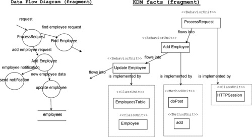 |
| Figure 49 Example of the behavior facts in the KDM Conceptual view |
Bibliography
ISO/IEC 19506 Architecture Driven Modernization—Knowledge Discovery Metamodel. (2009) .
Object Management Group, Knowledge Discovery Metamodel (KDM) 1.2. (2006) .
Object Management Group, Semantics of Business Vocabularies and Rules (SBVR) 1.1. (2009) .
[XMI] Object Management Group. XML Model Interchange (XMI)
W3C, Extensible Markup Language (XML) 1.0. 5th ed (2008) ; W3C Recommendation.
..................Content has been hidden....................
You can't read the all page of ebook, please click here login for view all page.