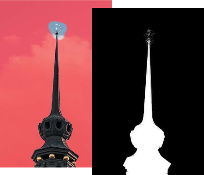
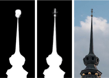
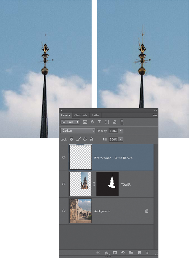
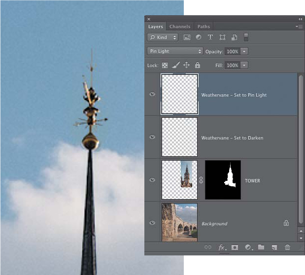
Chapter 9. Layer Masks

Some men have commitment problems when it comes to relationships—or so the old cliché goes. Well, we’ve met quite a few Adobe Photoshop users with deep-rooted commitment problems, and yes, we count ourselves among them. We fear the commitment of making an irrevocable image-editing decision that we’ll regret in the morning. In fact, if it wasn’t for one essential feature in Photoshop—layer masks—our work in Photoshop would be much more stressful.
Layer masks allow you to try various approaches and follow different idea paths in your images without losing the flexibility to change your mind. Layer masks are such an essential component in creating composite images that it’s difficult for us to get very far into a collage without using them. You’ve already seen many examples of layer masks in some of the illustrations in the earlier chapters. But now we’ll dive deep into the amazing possibilities that layer masks can bring to the creation of composites. Our explorations of layer masks in this chapter are a culmination of the material on selections and layers presented in Chapters 6, 7, and 8. In this chapter, you’ll learn:
• How to work with painted, gradient, and selection-based layer masks
• When to use pixel or vector layer masks
• Why layer masks are powerful, flexible, and creative
If we had to decide between giving up coffee or layer masks, we wouldn’t think twice. Some types of tea have caffeine, too! So brew a cup of your favorite beverage, and let’s explore one of the most exciting and essential features of Photoshop.
Working with Pixel Layer Masks
Layer masks are the soul of Photoshop compositing—the key to combining images in a completely nondestructive manner. They enable you to move, hide, blend, conceal, and experiment with image combinations to your heart’s content—all without ever harming a single pixel.
Each layer can support a pixel and a vector layer mask. Pixel-based masks are used for blending photographs together to gradually have images or tonal and color changes fade in and out, and wherever painted or soft-edge quality is desired. Vector-based masks are employed when the Bézier accuracy and crispness offered by the Pen tool are required. Both types of layer masks are very useful, but the pixel-based mask is the true workhorse of the compositing process.
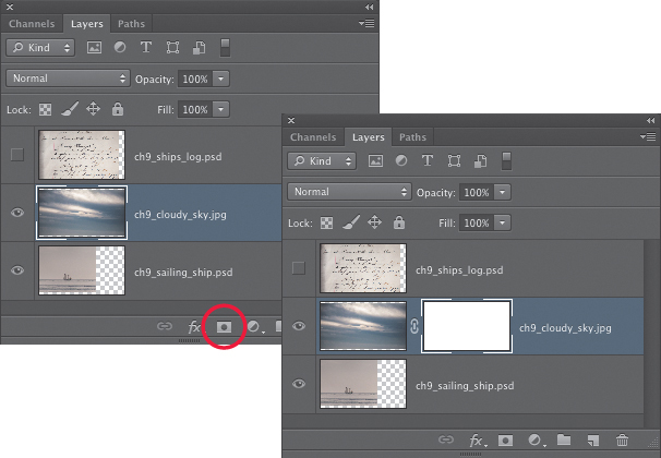
Background and type layers do not support layer masks. Adjustment layers automatically come with a layer mask. To add a layer mask to an image layer, either click the Add layer mask button in the Layers panel (FIGURE 9.1) to add a white layer mask, or Option-click (Alt-click) to add a black layer mask. You can also choose Layer > Layer Mask > Reveal All to add a white layer mask, or Layer > Layer Mask > Hide All to add a black layer mask.
Figure 9.1. Clicking the Add layer mask icon in the Layers panel will add a white layer mask to the active layer.
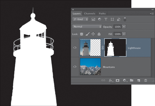
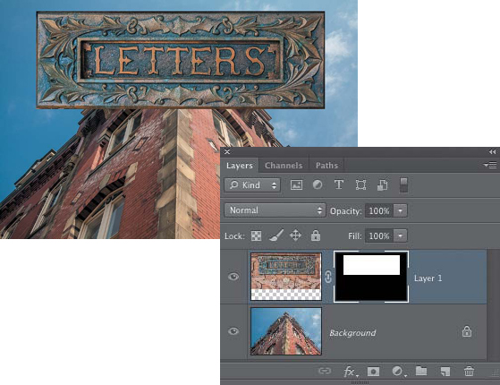
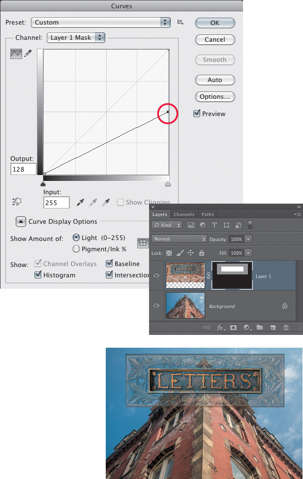
Just like an alpha channel mask that you create by saving a selection, pixel layer masks can be black or white with all shades of gray in between. Wherever the mask is darker, less of the layer will show through; wherever it is lighter, more of the layer shows through. In a nutshell, black conceals and white reveals—meaning that if you want part of an image to show through, the corresponding mask must be light. If you don’t want an image area to be visible, the mask must be black.
Selection-based Layer Masks
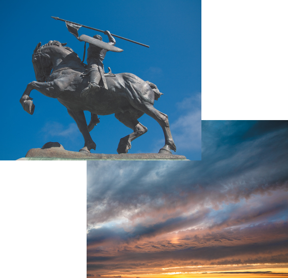
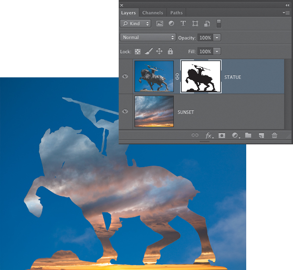
One of the most common ways to create a layer mask is to begin with a selection. This is a logical workflow when making a composite because isolating an element within an image typically begins with a selection. When a selection is active in the image, clicking the Add layer mask button will add a mask that shows the selected areas. If you Option-click (Alt-click) the Add layer mask icon, the layer mask will hide the selected areas. With an active selection, additional choices to reveal or hide the selection become available in the Layer Mask menu (Layer > Layer Mask). To explore this concept, we’ll revisit the image of the warrior statue from Chapter 6, “Selection Fundamentals,” and add it to a photo of a sunset (FIGURE 9.2).
© SD
Figure 9.2. The warrior statue and sunset images.
![]() ch9_warrior_statue.psd
ch9_warrior_statue.psd
ch9_sunset.jpg
1. Open the warrior statue and sunset images in Photoshop. To streamline this tutorial, we’ve already created an alpha channel of the warrior statue. This was made using the Magic Wand tool with Noncontiguous selected in the Options bar and the Inverse command (Select > Inverse), as shown in Chapter 6.
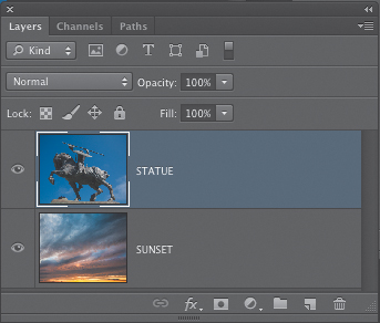
2. Bring the sunset image into the statue file by using the Move tool to drag and drop the sunset onto the statue, either from one document window to the other or by dragging the sunset image up to the statue name tab, as shown in the section “Moving Layers” in the previous chapter. If you hold down the Shift key as you release the mouse, it will center the sunset image over the stature photo (both images are the same size). Double-click the Background layer in the Layers panel to promote it to a regular layer. Then drag this layer above the sunset layer so that it is the top layer in the stack (FIGURE 9.3).
Figure 9.3. The Layers panel after moving the warrior statue layer to the top of the stack.
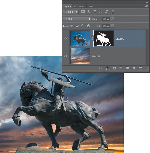
3. In the Channels panel, Command-click (Ctrl-click) the thumbnail for the Statue Selection alpha channel to load it as a selection in the image. With the selection active, click the Add layer mask icon at the bottom of the Layers panel. The resulting layer mask shows the areas that were selected and hides the non-selected areas (FIGURE 9.4).
Figure 9.4. With a selection of the statue active, adding a layer mask reveals the statue and hides the blue sky surrounding the statue.
4. Undo the layer mask by pressing Command+Z (Ctrl+Z). The selection should still be active in the file. If it’s not, reload it again from the Channels panel. Now, Option-click (Alt-click) the Add layer mask icon and the selected areas will be hidden instead of revealed (FIGURE 9.5). This is a very useful shortcut to know.
Figure 9.5. Option-clicking (Alt-clicking) the Layer Mask button will create a mask that hides the selected areas.
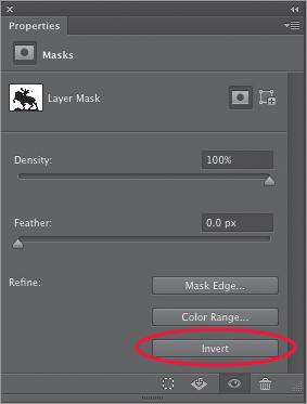
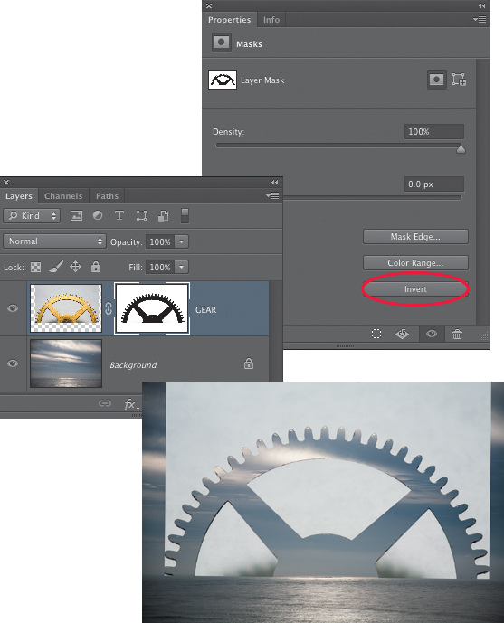
5. To return the layer mask to the state where it reveals the statue and hides the sky, click on the thumbnail of the layer mask to make sure it is active, go to the Properties panel, and click the Invert button (FIGURE 9.6). If you are using Photoshop CS4 or CS5, this functionality is in the Masks panel. We’ll take a closer look at the mask options in the Properties panel a bit later in this chapter.
Figure 9.6. The Invert button in the Properties panel will be available when a layer mask is active. It inverts the tonal values in the mask, making black white and vice versa.
When a layer mask is active, the highly useful keyboard shortcut for inverting a layer mask is Command+I (Ctrl+I).
Painted Layer Masks
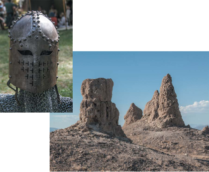
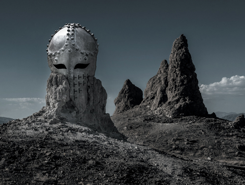
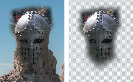
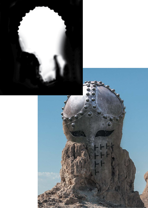
Although working with a layer mask that is generated from an active selection can yield very good results to reveal only portions of a layer (assuming, of course, that your selection was accurate), you can also control the visibility of a layer simply by painting directly on the mask. For some types of composites, this is a perfectly valid way of working. It all depends on the image you’re working with and how it needs to be blended with the other elements in the composite. In the following exercise, you’ll paint directly on a layer mask, as well as use selections to blend two photos of a steel helmet and desert pinnacles (FIGURE 9.7) into a strange mythical landscape (FIGURE 9.8).
© SD
Figure 9.7. The helmet and desert pinnacles images.
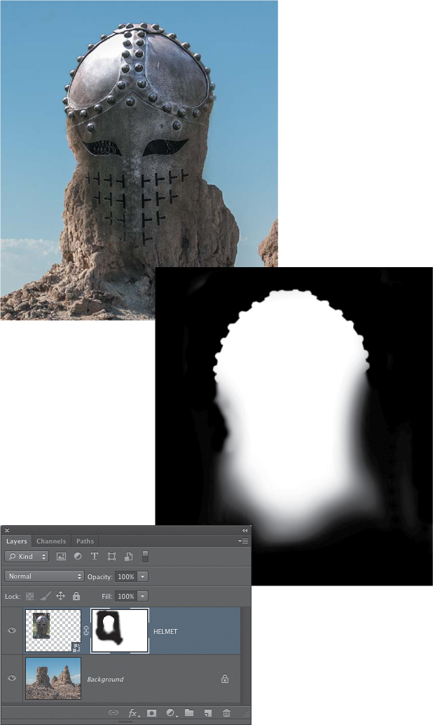
Figure 9.8. When the helmet image is blended into the landscape, it becomes reminiscent of a movie scene from The Lord of the Rings.
![]() ch9_helmet.jpg
ch9_helmet.jpg
ch9_pinnacles.jpg
Position and transform the helmet
The first thing to notice about the two images for this exercise is that the light is coming from different directions in each photo. In the helmet image the light is coming from the right; in the landscape shot it is coming from the left. To make a convincing composite, even if it is obviously fictional, as is the case here, you need to pay attention to the basic physics of the scene you are creating. And that means making sure that the light and shadows of the different elements work well together. To make the direction of the lighting match, one of the images needs to be flipped. For these photos, it doesn’t matter which one is flipped because there is nothing in either picture that would read backwards. Because the helmet is the smaller element in the composite, we’ll flip that one.
1. Open both images in Photoshop. Make the helmet image active and choose Image > Image Rotation > Flip Canvas Horizontal. If the helmet was already a layer in a composite, you could complete the same task by choosing Edit > Transform > Flip Horizontal.
2. Use the Move tool to add the helmet to the landscape image (if you need a review of how to do this, see “Moving Layers” in Chapter 8, “Layer Essentials”). Position it so that it is over the front pinnacle on the left side. Control-click (right-click) on the helmet layer in the Layers panel and choose Convert to Smart Object. By making the layer into a Smart Object, it will allow you to scale the helmet smaller without losing any pixels.
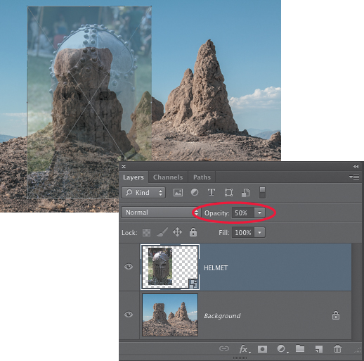
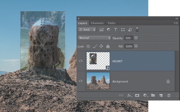
3. With the Helmet layer active, choose Edit > Free Transform. To help you see just how much smaller the helmet needs to be, lower the opacity of the layer to about 50% using the control at the top of the Layers panel (FIGURE 9.9).
Figure 9.9. Lowering the opacity of a layer lets you see the layer in relation to what is under it and can help you determine just how much scaling is needed.
4. Hold down the Shift and Option (Alt) keys, and drag inward on one of the corner handles of the transform bounding box. The Shift key will constrain the proportions of the helmet, and the Option (Alt) key will transform from the center point. Scale the helmet smaller so that it “fits” onto the area of the rock pinnacle. If you pay attention to the Options bar as you do this, you’ll see the width and height values change. For creating this exercise, we scaled the helmet down to 68% (FIGURE 9.10). When you are done scaling the helmet, press Return (Enter) to commit the transformation. Return the Helmet layer opacity back to 100%.
Figure 9.10. The helmet Smart Object scaled to 68%.
Create the Helmet layer mask
Now you need to create the Helmet layer mask.
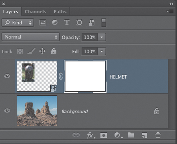
1. Click the Add layer mask icon to create an empty (white) layer mask for the Helmet layer (FIGURE 9.11). Before proceeding, double-check that black is the foreground color. If it is not, press D to set the default Foreground and Background colors in the Tools panel, and then press X to exchange them so the black is in the foreground swatch. Choose the Brush tool (B), and make sure that the brush opacity is 100% and the mode is Normal in the Options bar. Open the Brush Size picker on the left side of the Options bar, choose a soft-edged brush, and set the size to about 200 pixels.
Figure 9.11. An empty (white) layer mask is added to the Helmet layer.
2. Double-check to make sure that the layer mask is active in the Layers panel (look for the highlight border around the mask thumbnail). Begin painting over the outer edges on the helmet image to hide them from view (FIGURE 9.12). Don’t worry about being too accurate along the edges of the lower portion of the helmet. The only part of the helmet where the original edge will be preserved is the rounded top part.
Figure 9.12. The initial brush strokes on the layer mask hide the outer edges of the helmet image.
3. Use the Opacity slider in the Options bar to lower the brush opacity to 40%. You can also tap the number 4 on the keyboard to set the brush opacity to 40%. Working on the bottom part of the outer edges of the helmet, beginning just above the eyes, start to brush in to hide the helmet edges and reveal the rock. Use many very short brush strokes to do this. A brush stroke is a single motion of the cursor with the mouse button held down. When you release the mouse button, that ends a brush stroke. Adjacent to the eye openings on the helmet are sections where the jagged edges of the rock tower are showing. This is fine because it adds to the effect that the helmet is actually a part of the rock formation (FIGURE 9.13).
Figure 9.13. Additional brush work at 40% opacity “feathers” the edge even further, blending the helmet more with the rock tower. Turning off the visibility of the Background layer shows how the layer mask is hiding the helmet and blending it into the rocks.
Now it’s time to work on the top of the helmet. You can either paint out the background along the top, rounded part of the helmet, or you can use a selection. Both involve a moderate amount of tedium. We’ll cover the brush method first.
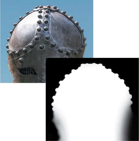
4. Zoom in to 100% (View > Actual Pixels), make your brush size 100 pixels, and begin to paint away the original background of the helmet image. When you get closer to the actual helmet edge, open the Brush Size picker on the left side of the Options bar, choose a much smaller brush size of about 30 pixels, and set the brush Hardness to 50%. Carefully paint out the background along the edge. As you get closer to the edge of the helmet and are working around the contours of the curved edge and the raised metal studs, you may need to decrease the brush size even more, and possibly increase the Hardness setting to create a harder, more accurate edge (FIGURE 9.14).
Figure 9.14. By carefully brushing along the top edge of the helmet with a small, harder-edged brush, you can create an accurate edge.
5. If you make a mistake and paint into the helmet, just press X to switch the foreground and background colors and paint with white to restore the edge of the helmet. That’s the beauty of working with layer masks. Image detail is never permanently erased; it’s only hidden!
Editing the Helmet mask with a selection
Applying the same edits to the mask with a selection can also work, but for this image, making the selection is not a quick, one-click operation. The tools to use are those that will “see” the contrast edges, such as the Quick Selection tool, the Magic Wand, or the Magnetic Lasso. The varying levels of hard contrast on the top of the helmet, however, make it challenging to create a selection using those tools. We settled on the Magnetic Lasso (the Pen tool is another good choice), but the operation was a combination of carefully guiding the Magnetic Lasso along the helmet edge and frequently clicking to manually set down an anchor point when the lasso became “confused” by the contrast. You can find a detailed discussion of using the Magnetic Lasso tool on a similar, high-contrast, metal edge in Chapter 6.
1. Before you begin, click on the Helmet layer thumbnail to make it the active part of the layer, as opposed to the layer mask. This will ensure that the selection is derived from the pixel information on the layer, not the black, white, and gray tones in the layer mask.
2. When you have a selection of the top part of the helmet, choose Select > Inverse. Everything except for that top edge should be selected. Click the thumbnail for the layer mask to make it active, and use the Brush tool to paint with black at 100% opacity to mask out the background part of the helmet image (FIGURE 9.15). When you’re done painting on the mask, choose Select > Deselect or press Command+D (Ctrl+D) to inspect the edges. Depending on how you made the selection, you may want to use the Feather slider in the Properties panel to slightly soften the edge. We feathered the mask by one pixel.
Figure 9.15. The image and the layer mask after editing the top part using a selection to protect the helmet part of the mask from the brush strokes that masked out the background.
Further mask edits with the Brush tool
Next, you’ll use the Brush tool to integrate the lower part of the helmet with the actual surface of the rock.
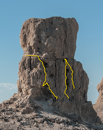
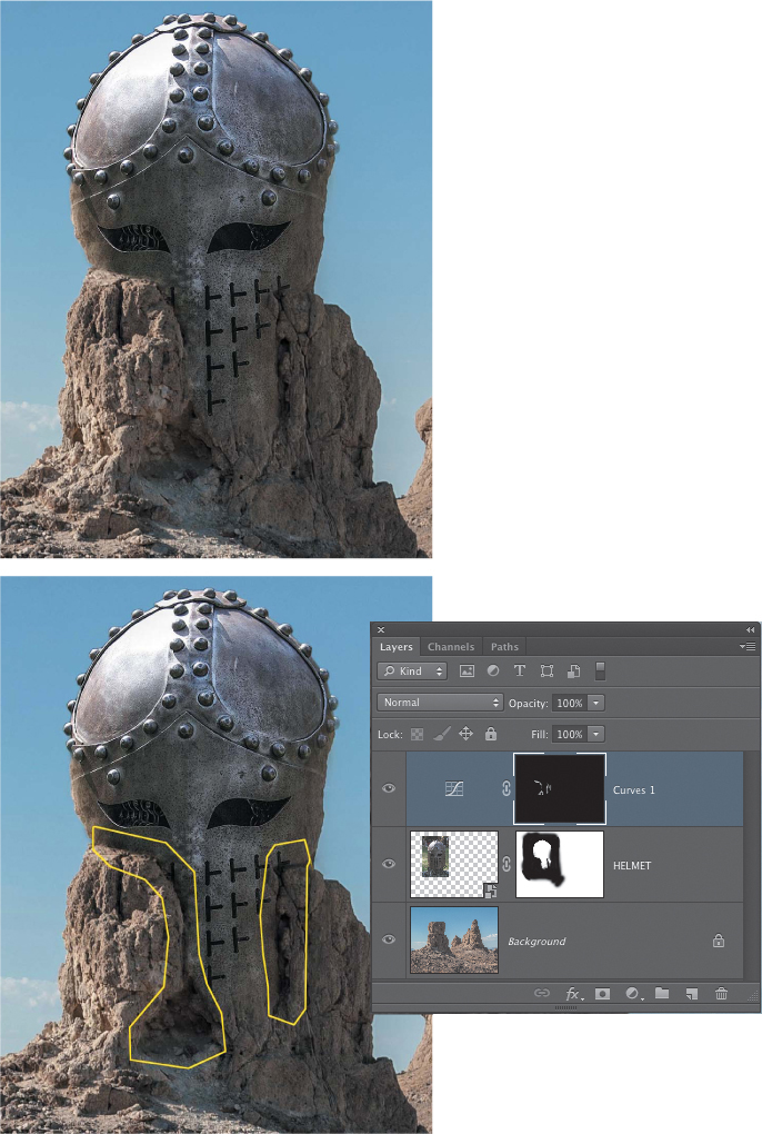
1. Click the eye icon for the Helmet layer to turn it off. Take a close look at the surface structures of the lower part of the rock column. Several deep fissures and cracks can be used to create a better blend for the helmet (FIGURE 9.16). The idea is to edit the lower part of the mask to selectively reveal some of these characteristics and make it appear that the helmet is actually built into the rock instead of just floating on top of it.
Figure 9.16. The yellow lines highlight actual edges in the rock that can be selectively revealed to create a more realistic blend between the helmet and the rock.
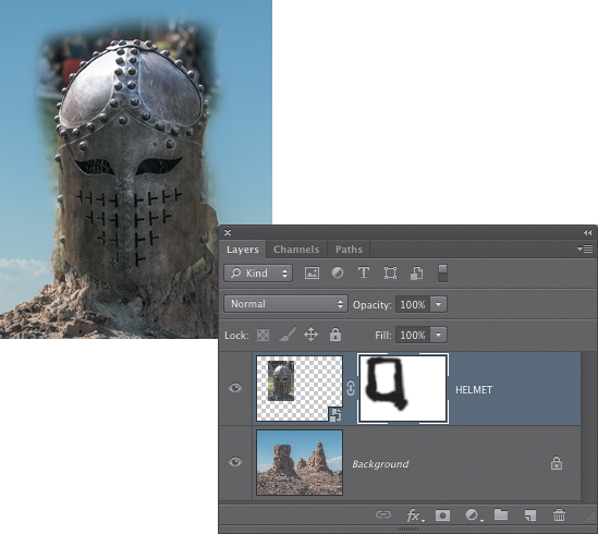
2. Turn on the visibility of the Helmet layer again and click the thumbnail of the layer mask to make sure that it is active. Lower the opacity of the layer to about 50% so you can see those cracks and fissures in the rock. With black as the foreground color, begin brushing over the areas where you want to hide the helmet. Once you’ve done that, return the layer opacity to 100% and continue to fine-tune the integration of the helmet with the rock. There are no exact instructions on how to do this, and there will be a lot of back and forth as you switch between black and white while editing the mask. You can see the finished version of our edits to the Helmet mask in FIGURE 9.17.
Figure 9.17. Editing the layer mask so that it fits with actual details on the rock can help to create a more convincing blend between the helmet and the rocky pinnacle.
Adding shading with adjustment layers
The edits to the lower part of the layer mask look good, and the helmet looks more like it is actually a part of the rock structure. However, some additional shading will make that effect even better. To do this, you can use an adjustment layer to apply a darkening effect and then paint on the layer mask for the adjustment layer to show the darkening only where you want it.
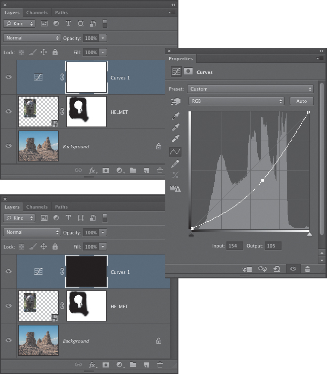
1. Click the Create new fill or adjustment layer button at the bottom of the Layers panel to add a Curves adjustment layer. In the Properties panel, pull down a bit on the center of the curve, as shown in FIGURE 9.18. The entire image will become darker. Press Command+I (Ctrl+I) to invert the layer mask to black, which will hide the darkening adjustment.
Figure 9.18. A Curves adjustment layer is added to darken the entire image. When the layer mask is inverted to black, the darkening can be painted in to create effective shading.
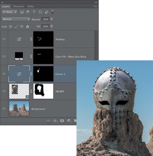
2. Use a small, soft-edged brush and paint with white at 50% opacity to brush in the shading on the helmet where it makes sense. This will be along the cracks and fissures in the rock that form the edge between the helmet and the rock. The main objective is to enhance this edge so that it is more noticeable and so that the helmet looks slightly recessed into the surface of the rock. In the version shown in FIGURE 9.19, we also darkened the small triangular opening at the base of the rock pillar.
Figure 9.19. The first image shows the composite before any shading. The second image shows the result of painting in the shading using the Curves adjustment layer mask.
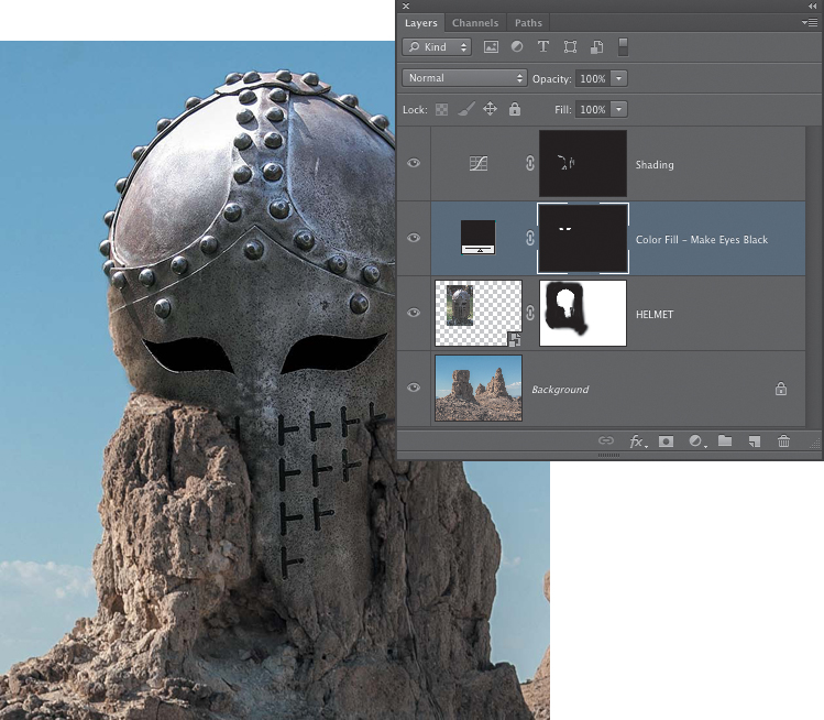
3. Another place where some shadows would come in handy are the eye openings in the helmet. A little bit of the chain mail shirt the helmet was resting on is still visible there. Click on the Helmet layer and use the Quick Selection tool to make a selection of the eye openings. When you have both eyes selected, click the Create new fill or adjustment layer button to add a Solid Color Fill layer. In the Color Picker dialog that appears, set the color to black and click OK (FIGURE 9.20). Use the Brush tool to apply fine-tuning edits to the mask (make sure that the highlight edges of the eye openings are not affected by the addition of black to the interior part of the openings).
Figure 9.20. Using a Solid Color Fill layer and a layer mask to add black to the eye openings.
Adding highlights with adjustment layers
As you view the image, the left side of the helmet around the eye opening seems a bit dark considering the bright sunlight in the scene. Just as you added an adjustment layer to create shading, you can do the same to create or enhance a highlight.
1. Option-click (Alt-click) on the layer mask thumbnail for the Helmet layer to reveal the black and white mask. Use the Quick Selection tool to click inside the white area that defines where the mask will be visible. This will create a selection that conforms to the visible areas of the mask in the composite. When you have the selection, click on the Helmet layer thumbnail to return to the standard view of the image.
Using the existing mask is a great way to take advantage of work you’ve already done. If you’re wondering why we simply did not load the entire mask as a selection by Command-clicking (Ctrl-clicking) it, it’s because that would also load all of the white areas surrounding the parts where we painted with black. Viewing the black and white mask and clicking inside the white area with the Quick Selection tool loads only that part of the mask as a selection.
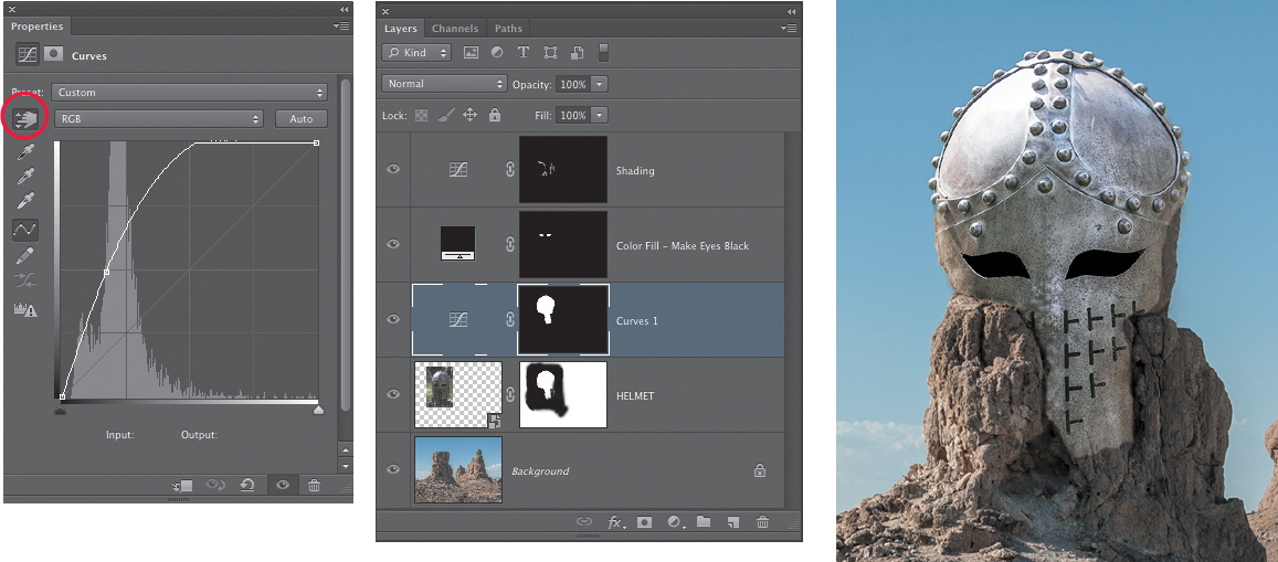
2. With the selection active, add a Curves adjustment layer. Click the targeted adjustment tool in the upper-left corner of the Curves Properties panel, and then in the image, drag up on the darker area of the helmet under the left eye opening (FIGURE 9.21). This is the main area you want to lighten a bit. Don’t be concerned if other areas of the helmet become too bright; you’ll fix that in the next step.
Figure 9.21. Lightening the helmet with a Curves adjustment layer.
3. Use the Brush tool and paint with black at 40% opacity to tone down the brightening where you don’t want it to show. To completely remove the brightening, paint over an area using multiple brush strokes (release the mouse button to end one stroke and then start another). In the example shown in FIGURE 9.22, we ended up brightening only the left side of the helmet around the eye opening and a little bit above that eye. The primary goal is to enhance the light that is shining onto that side of the helmet, so it should be a bit brighter than the other side. When you adjust the mask after lightening the helmet, make sure that you do not lighten any of the shading along the rock and helmet edges that you already added with the earlier Curves layer.
Figure 9.22. The layer mask for the Curves layer that lightens the helmet is modified to show only the lightening on the left side around the eye opening.
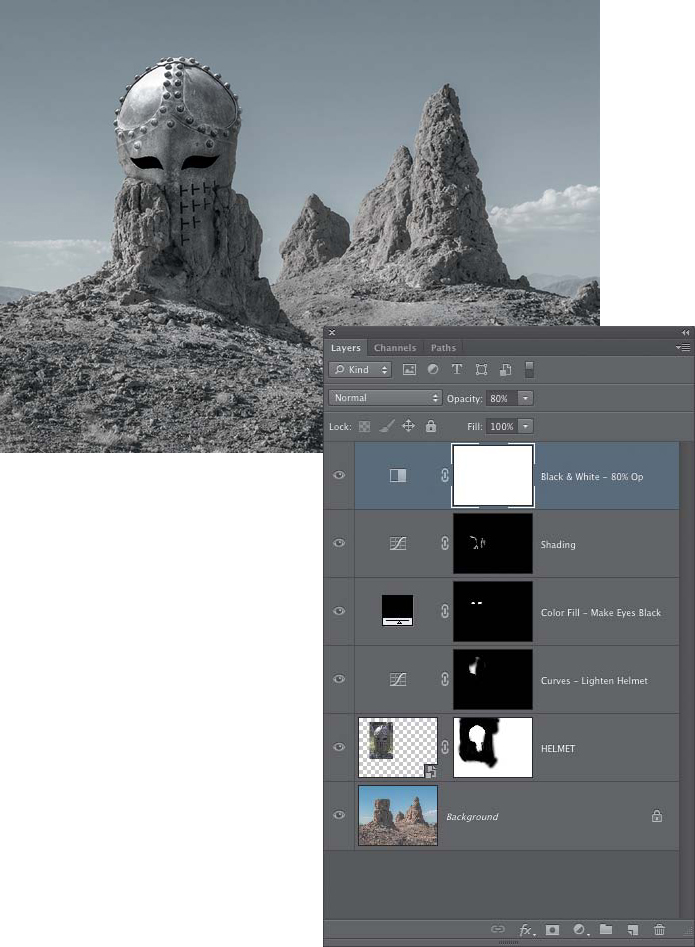
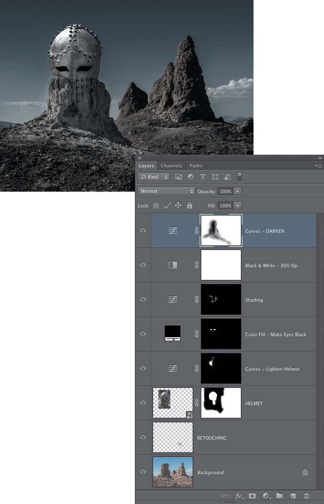
After the main compositing work was done on this image, we added a Black & White adjustment layer and set the layer opacity to 80% to desaturate the scene and let just a little of the original color show through (FIGURE 9.23). Then we added a Curves adjustment layer to darken the overall scene and create a more moody and foreboding atmosphere (FIGURE 9.24). We used the Brush tool to paint on the layer mask so that the helmet and parts of the rock pinnacle did not get too dark. We also added a retouching layer immediately above the background and used the Clone Stamp tool and the Healing Brush to retouch some of the tire tracks in the background.
Figure 9.23. A Black & White adjustment layer set to 80% opacity is added to desaturate the entire scene.
Figure 9.24. A Curves layer is used to darken the entire image. The layer mask for the Curve is then edited to prevent the helmet from getting too dark. A retouching layer was also added for removing the tire tracks in the background.
Editing a layer mask with the Brush tool and painting with black or white to conceal or reveal the content of a layer may not be as precise as creating a mask from a carefully prepared selection, but as you can see from this exercise, you can accomplish quite a lot with this method. Not all image composites may require the exact precision of an accurate selection, such as the lower part of the helmet where it blends with the rock. As you saw with the upper part of the helmet, you can also use the Brush tool in combination with a selection to restrict the brush strokes to a specific area. In the next section we’ll explore how to use the Gradient tool to create subtle and gradual transitions from one image to another.
Gradient Layer Masks
The largest “paintbrush” in Photoshop is the Gradient tool. It enables you to create subtle transitions from one color or tone to another. When used to edit a layer mask, the Gradient tool makes it very easy to seamlessly blend images together. It is an essential part of the image-compositing tool kit. In this section, we’ll look at several ways to use gradients in layer masks to combine images in different ways, as well as to apply color and tonal corrections in adjustment layers. We’ll also explore how a gradient layer mask can be combined with other masking techniques and blending modes to create even more image-blending possibilities.
Gradient tool overview
Before we get to blending images with the Gradient tool, let’s take a quick look at how it works and how you can use it to create exactly the type of gradient you need. If you want to experiment as you read this section, create a new, blank file in Photoshop (File > New). In the New File dialog, set the background color to white. For this quick overview, the size of the document does not matter.
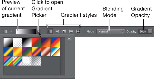
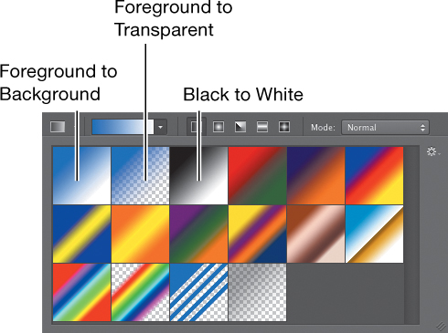
The Gradient tool creates a transition from one color to another. In some cases, you can even create gradients that transition between several colors or tones. In the Options bar for the Gradient tool, you can open the Gradient Picker to select the colors and choose a style for how the gradient will be applied in the image (Linear, Radial, Angle, Reflected, or Diamond), as well as determine the blending mode, opacity, and a few other options (FIGURE 9.25). In the Gradient Picker, the first three swatches are probably the ones you’ll use the most often (at least for masking purposes). From left to right they are Foreground to Background, Foreground to Transparent, and Black to White (FIGURE 9.26). The appearance of the first two will vary depending on what the foreground and background colors are set to. When you add a layer mask, the foreground and background colors will be black and white by default. The third swatch, Black to White, is one that you will rely on a lot when creating gradient masks.
Figure 9.25. The Options bar for the Gradient tool.
Figure 9.26. The Gradient Picker.
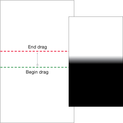
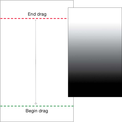
The default gradient style is Linear, which means the gradual transition will occur along a straight line. When you drag in the image to create a gradient, where you begin dragging represents 100 percent of the starting color, and where you stop will be 100 percent of the ending color. Everything in between those two points will be the gradient transition between the two colors. Dragging a short line will result in a shorter and more abrupt transition (FIGURE 9.27). Dragging a longer line will create a longer and more gradual transition (FIGURE 9.28).
Figure 9.27. Dragging a short line with the Gradient tool will result in a short gradient transition. This is a Black (starting color) to White (ending color) Linear gradient.
Figure 9.28. Dragging a long line with the Gradient tool results in a long and gradual transition. This is a Black (starting color) to White (ending color) Linear gradient.
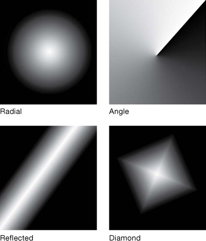
In addition to the default Linear gradient, you can also choose from Radial, Angle, Reflected, or Diamond gradients (FIGURE 9.29).
Figure 9.29. Clockwise from upper left, a white to black Radial gradient; a black to white Angle gradient; a white to black Reflected gradient; and a white to black Diamond gradient.
Image blending with gradient masks
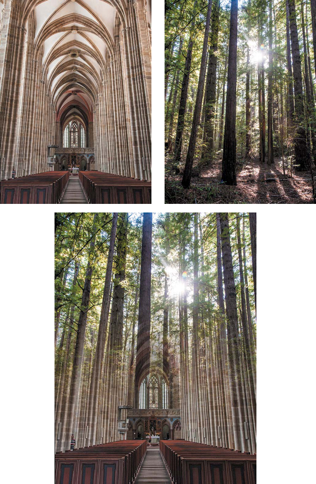
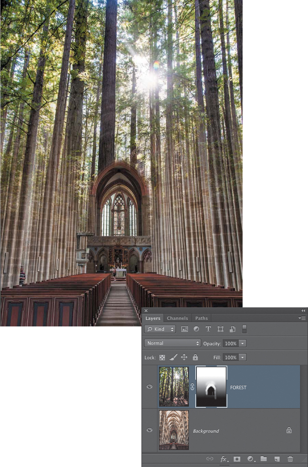
Blending images together using a gradient layer mask is a quick and easy way to jump-start the collage process. For some image pairings, you may be able to rely entirely upon the Gradient tool to help create the composite; for other images, applying further edits to the layer mask or using blending modes may be required. We’ll start with a simple gradient blend between a grand European cathedral and a California redwood forest (FIGURE 9.30).
© SD
Figure 9.30. The cathedral and forest images and the composite blend of the two created using a gradient layer mask.
![]() ch9_cathedral.jpg
ch9_cathedral.jpg
ch9_redwood_forest.jpg
When you’re opening multiple files that you want to composite together, in Adobe Bridge you can select the thumbnails of the images you want to open and choose Tools > Photoshop > Load Files into Photoshop Layers. Adobe Lightroom has a similar command when you have more than one image selected: Choose Photo > Edit In > Open as Layers in Photoshop.
1. Open the two images you want to blend, and determine which one will serve as the base image and which one will be the top layer. For the cathedral-forest collage, the cathedral is the base image. Add the forest image to the cathedral photo. You can either drag from the cathedral image up to the name tab of the forest file and then down over the image and release the mouse, or if you can see both document windows at the same time, you can drag from one window to the other. When you’re using the Move tool to drag images from one document to another, make sure that your cursor leaves the first image entirely. Otherwise, Photoshop will display the polite yet irritating message, “Could not use the Move tool because the layer is locked.” Pressing and holding the Shift key as you release the mouse will place the top image exactly on the center point of the bottom image. If the two photos are the same size, as is the case with the cathedral and forest images, they will be perfectly aligned.
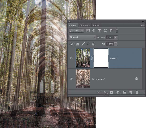
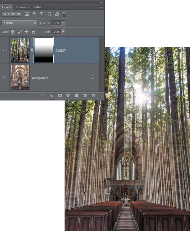
2. Add a layer mask to the top layer (the Forest) and reduce the layer opacity to 50%. This will help you find the best position for the gradient transition, because you can see through to the cathedral layer underneath (FIGURE 9.31).
Figure 9.31. After adding a layer mask to the Forest layer, lower the opacity to about 50% so you can see the relationship between the two images.
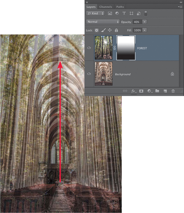
3. Click on the thumbnail of the Forest layer mask to make sure it is active, and select the Gradient tool in the Tools panel. In the Options bar, open the Gradient Picker and choose the third gradient from the left—Black to White. Make sure that the style is set to Linear, the blending mode is Normal, and the Opacity is 100%; the Reverse check box should not be selected. Start the gradient where you want the bottom image (the cathedral) to show through completely and draw up. Release the mouse when you reach the point in the top image that you want to see completely. In this example, we began dragging the gradient at the top of the white altar and ended it at the large circular opening in the ceiling about a third of the way down from the top edge of the image (FIGURE 9.32).
Figure 9.32. Using a Black to White gradient to reveal the lower part of the cathedral image and show the upper part of the forest photo.
4. Increase the Forest layer opacity to 100% to see the results (FIGURE 9.33).
Figure 9.33. With the Forest layer opacity set to 100%, the full blending effect of the gradient mask is revealed.
5. Now that you can see the blend of both images better, you can redraw the gradient to try out shorter or longer gradients, or place the start and end points of the gradient in a different position. With the Gradient blending mode set to Normal, every time you drag out a new gradient, it will replace the previous one. Just make sure that the layer mask is the active part of the layer; otherwise, you’ll add a gradient to the actual image layer and obliterate the photo!
When you’re editing a layer mask with the Gradient or Brush tools, always double-check that the mask thumbnail is the active part of the layer before applying your edits. A thin highlight border around the thumbnail denotes that it is active.
Adjusting position
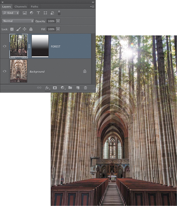
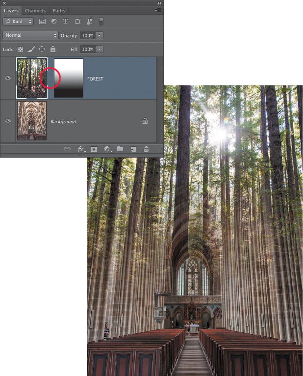
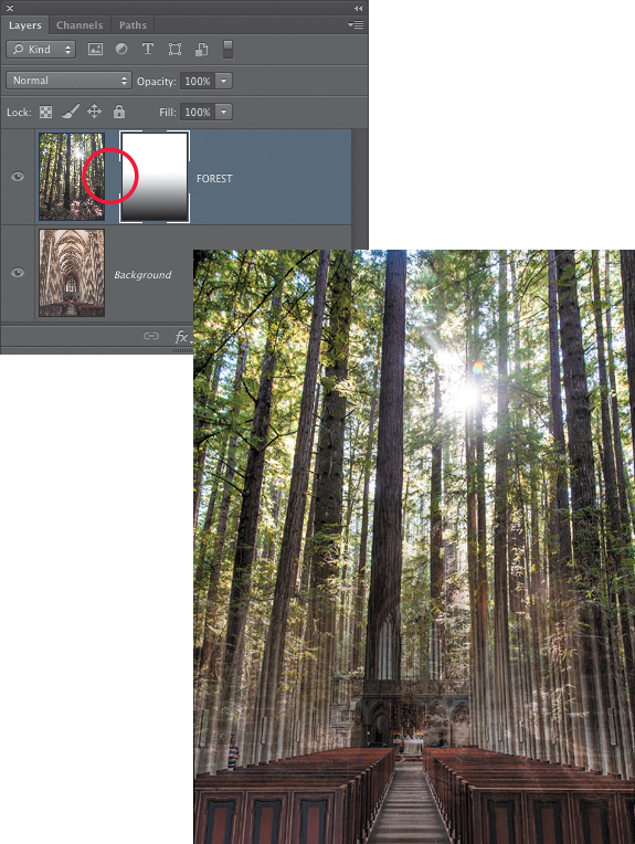
The layer and the layer mask can be moved together or independently of one another. The default condition for most layer masks is that they are linked to the layer. To move the layer and mask together, look for the chain link icon between the layer and layer mask thumbnails. This indicates that the two are linked and both will move as a single unit. To move either one separately, unlink them by clicking the small chain icon between the two thumbnails. The link icon will disappear and the layer or the layer mask will then move independently.
To change the position of the forest, do one of the following:
• Move the forest image with the layer mask (FIGURE 9.34) by using the Move tool to reposition the layer. Because the top edges of both photos are aligned, moving the Forest layer upward is the only option in this case.
Figure 9.34. Moving the Forest layer and its layer mask together so that the sun is positioned higher in the composite. This reveals more of the cathedral.
• Move just the Forest layer but not the layer mask by unlinking the forest pixels from the layer mask. Click the small chain between the layer and layer mask thumbnails (FIGURE 9.35), and then make sure the layer is active before moving it.
Figure 9.35. Moving the Forest layer but not its layer mask. The sun is positioned higher in the composite, but the forest still covers the same area of the cathedral.
• Move just the layer mask by unlinking the Forest layer pixels from the layer mask. If the layer and layer mask are still unlinked from the previous step, just click on the thumbnail of the layer mask to make it the active element, and then drag in the image with the Move tool to move the mask (FIGURE 9.36).
Figure 9.36. Moving the layer mask independently of the layer is useful for fine-tuning the transition point between the two images. In this example, the layer mask has been moved down to reveal more of the forest image and less of the cathedral.
Many times you’ll want the mask to stay linked with the layer, but very often it is quite useful to move the layer mask—for example, when the length of the gradient blend is perfect, but you want to change its position slightly.
Experimenting with the Gradient tool
The best thing about the Gradient tool and layer masks is that you can redo the blend over and over again to get the image exactly right. We’ve provided a few variations in FIGURE 9.37. Every time you draw a new gradient, the previous blend is overwritten, letting you experiment to your heart’s content.
Figure 9.37. Experiment with the length and direction of the gradients you add to a layer mask to create different blends between the two layers.
Take a moment to experiment with the Gradient tool: Create very steep transitions by dragging the gradient line for only a short distance; create a very long transition by dragging the gradient across the entire image. Try it going from right to left, or diagonally, or take one of the other gradient styles for a test drive.
Gradients do not have to be constrained within the boundaries of the document. If you are viewing the image in Full Screen with Menu Bar mode (tap the letter F on the keyboard to cycle through the screen view modes), you can start and end the gradient drag in the empty gray areas surrounding the image. This allows for gradients with much longer and gentler transitions.
Editing a gradient mask with the Brush tool
Often, an image combination requires more than a straight-line gradient to blend in a new image, and you may need to apply additional edits to the layer mask after the initial gradient has been applied. In the forest cathedral image, for example, the Linear gradient that reveals the forest at the top and the cathedral at the bottom works pretty well, but a few simple edits with the Brush tool can enhance the mask and take the composite to another level by showing more of the window behind the altar (FIGURE 9.38).
Figure 9.38. Editing the initial gradient mask with the Brush tool reveals more of the window behind the altar.
Combining a gradient mask with blending modes
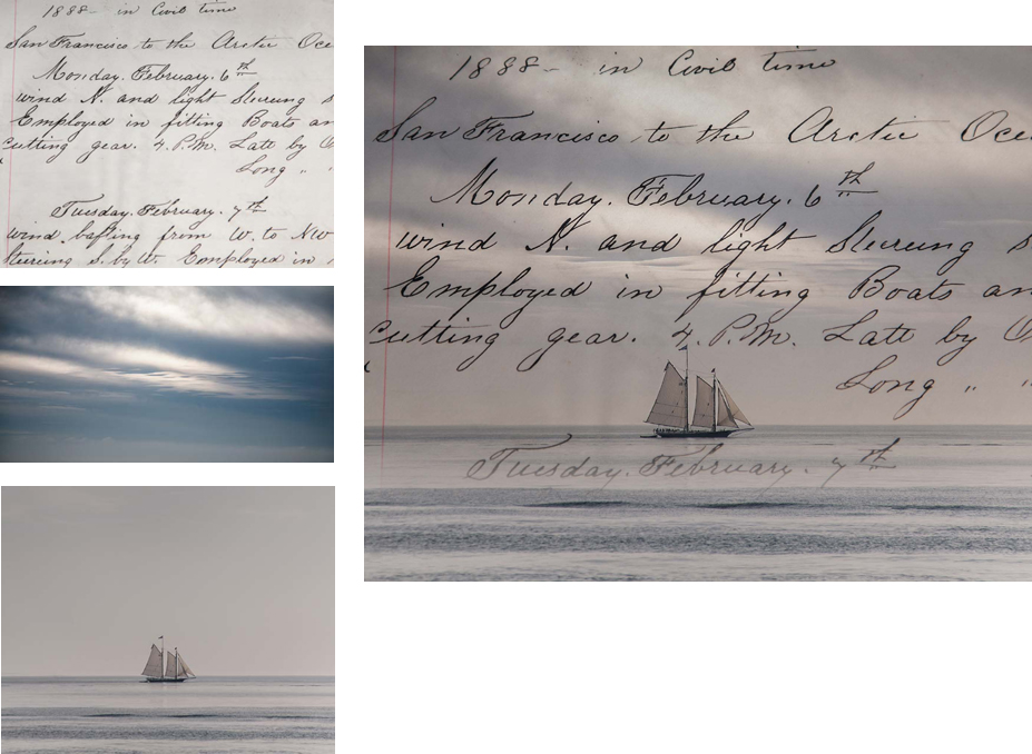
Although a gradient mask can create very interesting and highly customizable transitions between images, be sure to try some of the blending modes. Depending on the characteristics of the layer you want to blend, the combination of a gradient mask and a blending mode can often create just the right effect (FIGURE 9.39).
© SD
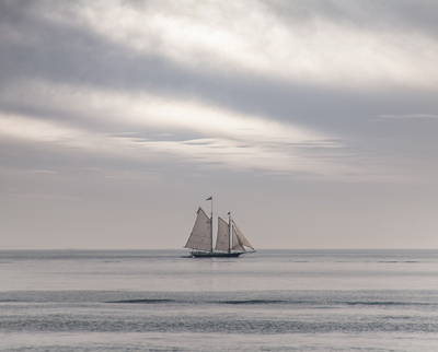
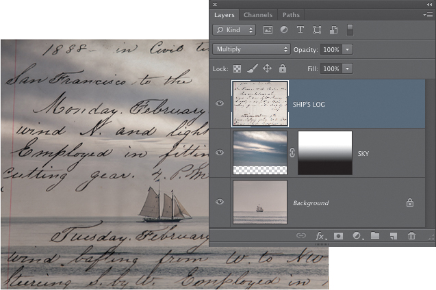
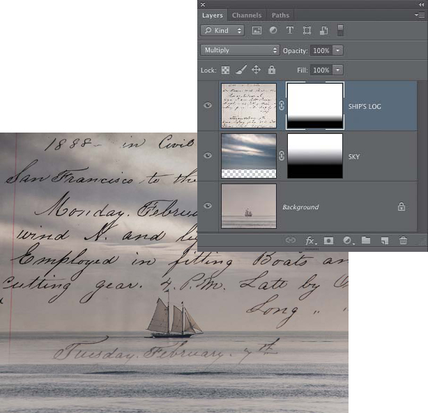
Figure 9.39. The ship’s log, cloudy sky, and ship images, and the composite blend of the three, were created using gradient layer masks and blending modes.
![]() ch9_sailing_ship.jpg
ch9_sailing_ship.jpg
ch9_ships_log.jpg
ch9_cloudy_sky.jpg
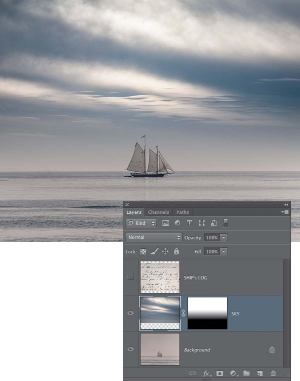
1. Open the three images, and bring the ship’s log and the cloudy sky into the sailing ship image. Arrange the layers so that the ship is on the bottom, followed by the sky, and then the ship’s log. Turn off the visibility for the Ship’s Log layer, and add a layer mask to the Sky layer.
2. Using the Gradient tool, add a Black to White gradient to the Sky layer mask so that the ship is visible beneath the new sky. For this example, we dragged up from the horizon line of the ocean to the middle of the bright diagonal cloud in the center of the sky (FIGURE 9.40). Feel free to experiment with different gradient lengths to create the blend that works for you.
Figure 9.40. A gradient added to the Sky layer mask creates the initial blend between the sky and ship images.
3. The gradient mask works well to blend the sky with the ship. However, depending on how long you made your gradient, you may notice that the top flag on the mast looks a bit as if it was covered by the cloudy sky. To edit this, you could try painting very carefully on the mask with a tiny brush so that the flag appears at normal opacity, or you could try a blending mode. We’ll take the latter approach. Change the blending mode for the Sky layer to Overlay (FIGURE 9.41). This lets the ship’s mast and flag show through at normal strength and also blends the colors of the sky better with the underlying image. You might also want to try the Soft Light and Hard Light blending modes.
Figure 9.41. Changing the blending mode for the Sky layer to Overlay creates a better blend with the ship’s mast and flag, and matches the underlying sky color.
4. Turn on the visibility for the Ship’s Log layer. Because this is dark text on a white background, we’ll let a blending mode do most of the heavy lifting here. Change the blending mode for this layer to Multiply to create a pleasing blend where the writing appears but the page does not. Multiply is an excellent blending mode to use with written materials, such as old letters, diary pages, tickets, passports, or any type of printed document, where the text is dark and the page is light. The brighter the page, the less the light areas will show. In this case the page slightly darkens the entire image but not by much (FIGURE 9.42).
Figure 9.42. The Ship’s Log layer is set to Multiply.
5. In many cases when you’re working with images of old printed documents, using the Multiply blending mode alone will be all that you need to create a seamless and convincing blend between that layer and the rest of the composite. To customize the blending effect even further, add a layer mask to the Ship’s Log layer and then use the Gradient tool to add a gradient to the mask so that the writing fades out under the ship, as shown in FIGURE 9.43. The gradient that we drew began just under the tail of the letter “y” in “February” and extended up to the horizon line.
Figure 9.43. A gradient mask is added to the Ship’s Log layer to fade the text below the ship.
If you are working with a layer that has light-colored text against a dark background, use the Screen blending mode to show the lighter areas but not the darker parts of the layer.
Combining a gradient with a precise mask
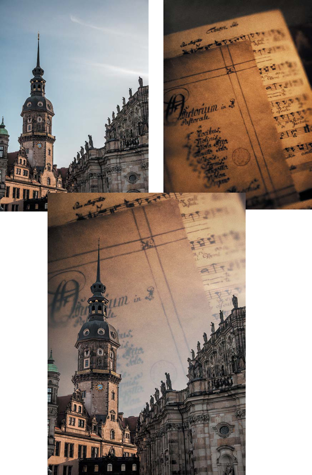
So far in your explorations of layer masks, you’ve seen that in some cases you may have to employ more than a single masking technique. In this section you’ll explore two ways to combine a precise, hard-edged mask with the softer transitions of a gradient (FIGURE 9.44).
© SD
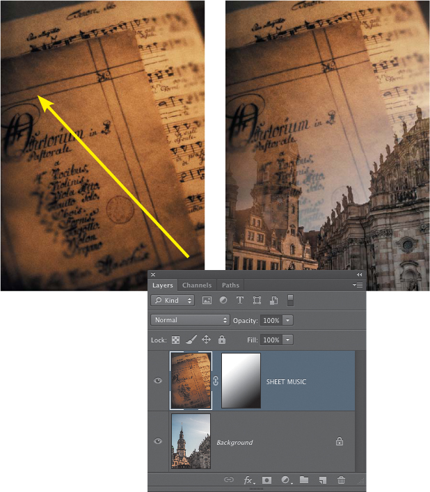
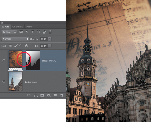
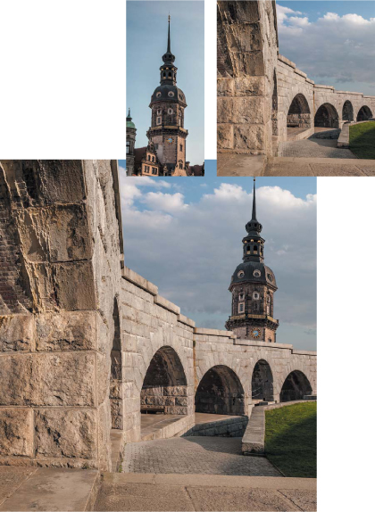
Figure 9.44. The original Dresden and antique sheet music images, and the final composite created using a layer mask that is a combination of a precise mask with a gradient.
![]() ch9_dresden.psd
ch9_dresden.psd
ch9_antique_sheet_music.jpg
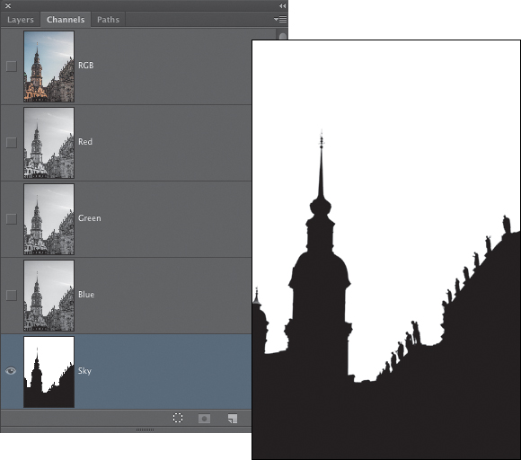
1. Open the Dresden and antique sheet music images. If you check the Channels panel for the Dresden image, you’ll see that a precise mask is already defining the sky (FIGURE 9.45). This mask was made using the Quick Selection tool to make the initial selection of the sky along with the Refine Edge dialog, as discussed in Chapter 7, “The Essential Select Menu.”
Figure 9.45. The alpha channel of the sky in the Dresden image.
2. Bring the sheet music into the Dresden image as a new layer. Add a layer mask to the Sheet Music layer and then use the Gradient tool to add a Black to White gradient to the mask. Drag diagonally from the lower-right corner to the upper-left corner, as shown in FIGURE 9.46.
Figure 9.46. Adding a gradient to the Sheet Music layer mask.
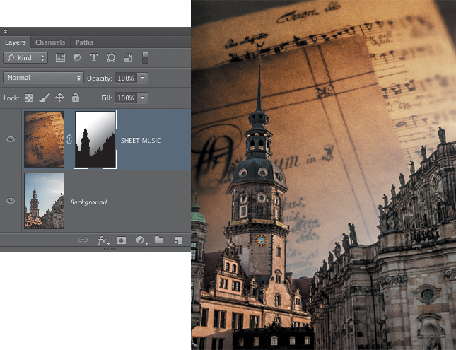
3. In the Channels panel, Command-click (Ctrl-click) on the sky alpha channel to load it as a selection. This creates a selection of the sky, but to edit the mask so that the buildings are not covered by the sheet music, you need to have the buildings selected. Choose Select > Inverse to inverse the selection so that the buildings are selected.
4. In the Layers panel, click on the thumbnail of the Sheet Music layer mask to make it active. Press D to set the default foreground and background colors. When a mask is active, this will place black in the background color swatch. Press Delete to fill the selected area with black. The buildings are no longer covered by the music (FIGURE 9.47). Choose Select > Deselect.
Figure 9.47. Filling the selected area on the layer mask with black adds the precise shape from the alpha channel to the existing gradient mask.
To edit the gradient without affecting the precise silhouette of the buildings, you would have to reload the selection of the sky area and then drag out new gradients until you found one that you liked. That approach does work, but there is a more elegant way to do this, and a blending mode is the key.
5. Throw away the layer mask for the Sheet Music layer by dragging its thumbnail to the trash icon at the bottom of the Layers panel. When prompted whether to apply the layer mask or delete it, click Delete.
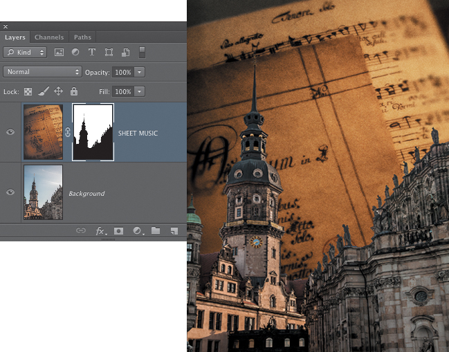
6. Load the selection of the sky from the saved alpha channel in the Channels panel. In the Layers panel, make sure the Sheet Music layer is active and click the Add layer mask icon at the bottom of the panel. The resulting layer mask is based on the selection that was active when the mask was created (FIGURE 9.48).
Figure 9.48. A layer mask based on the selection of the sky alpha channel.
7. Now choose the Gradient tool. To add the gradient without ruining the lovely precise silhouette of the buildings, in the Options bar for the Gradient tool, set the blending mode to Darken (FIGURE 9.49). The Darken blending mode will preserve any tone that is darker than the color that is being applied with the gradient. Because nothing is darker than black, the existing shape of the buildings will be preserved (FIGURE 9.50).
Figure 9.49. The Options bar for the Gradient tool with the blending mode set to Darken.
Figure 9.50. When a gradient is applied using the Darken blending mode, any tones that already exist in the mask that are darker than the gradient will be preserved.
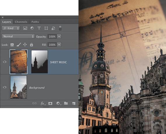
8. To try different applications of the gradient, you need to undo after each drag of the Gradient tool by pressing Command+Z (Ctrl+Z). The Darken blending mode will not allow you to just drag out a new gradient to replace the old one, as you can when the blending mode is set to Normal. Still, this is an easier way to preserve the precise shape of the buildings in the layer mask and easily experiment with different gradient applications. For the final image shown in FIGURE 9.51, we unlinked the Sheet Music layer from its layer mask and moved the layer up so that more of the first word on the top sheet could be seen. The gradient was dragged from the round window in the lower right to the top-left corner of the image.
Figure 9.51. For the final composite, the Sheet Music layer was unlinked from its layer mask and moved up a bit in relation to the tower.
If there are light areas in a layer mask that you want to preserve, set the Gradient tool blending mode to Lighten.
The previous examples have utilized the Linear style for the Gradient tool. The other styles are also quite useful and can sometimes create unexpected results. Try using the Radial, Angle, Reflected, and Diamond gradients on a layer mask to see how they affect the blending of two images. Use a Black to White gradient, and also try selecting the Reverse check box in the Options bar for the Gradient tool to see how the blends are different if the tones in the gradient are reversed.
Gradient masks for tonal adjustments
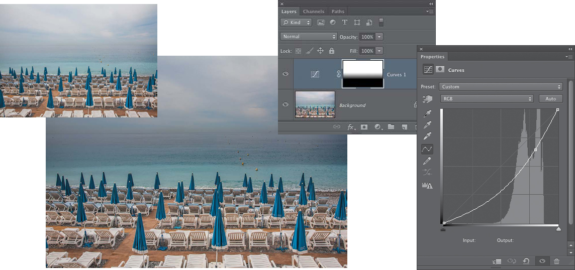
Gradient masks are one of the most useful masking techniques for compositing, but they can also be used with adjustment layers to customize how color or tonal adjustments are applied. Whenever you have a color or tonal correction that is applied at full strength in one part of the image but then needs to gradually fade out to where it is not affecting the image at all, a gradient layer mask can control how the adjustment is applied. FIGURE 9.52 shows a Curves darkening adjustment applied to a photo of a beach on the French Riviera. A gradient in the layer mask applies the darkening only to the top half of the image and then gradually fades to where the lower portion is not being affected at all.
© SD
Figure 9.52. Gradient masks are also highly useful for applying tonal adjustments to specific parts of an image.
Vector Layer Masks
Pixel layer masks are made up of a grayscale mask that defines the visibility of a layer using tones of white (visible), black (not visible), or gray (partially visible). Vector masks define the visible areas of a layer using Bézier paths created using the Pen tool or the Shape tools. The path that makes up a vector mask can be edited with great precision to create a smooth and hard-edged shape. Vector masks are ideal for those imaging situations in which you need to have a precisely defined edge on a layer, and that edge needs to be hard and smooth. Vector masks are exceptionally well suited for masking image elements that have long curved segments as part of their shape.
Although a vector mask is perfect for hard-edged, precise accuracy, it is not the technique to use when you need indistinct and more organic edges, such as frizzy hair, delicate leafy trees, or any edge that requires a gradual and subtle transition. Generally speaking, vector masks are best for shapes and forms that are manufactured, whereas pixel layer masks are better at defining the edges of natural forms and shapes. There are exceptions, of course, such as smooth, polished rock formations, which can be good candidates for a vector mask. But for the most part, a pixel layer mask will work better with natural shapes.
Creating Vector Masks
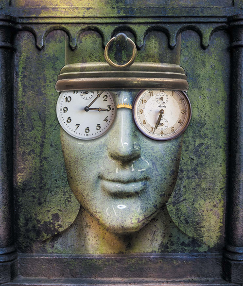
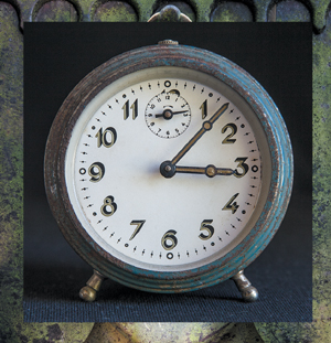
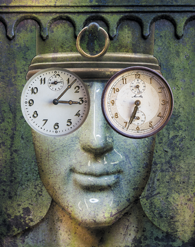
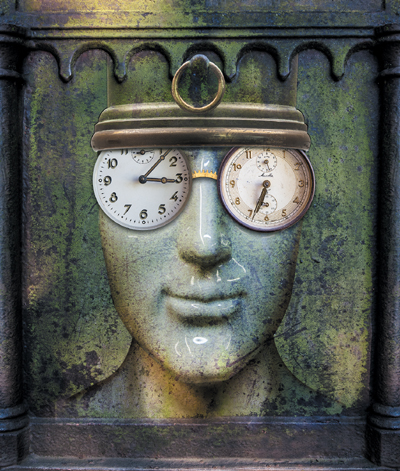
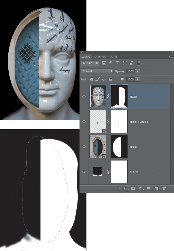
To add a vector mask to a layer, you first need to have a path in the Paths panel. Paths can be created using the Pen tool or by using one of the Shape tools to create a path based on a predefined shape preset. We cover the Pen tool in detail in the web-based chapter “Pen Tool Power.” In this section, we’ll concentrate mainly on how to turn an existing path into a vector mask, and how to modify it and combine it with a pixel layer mask. To explore the possibilities of vector masks, we’ll work with photos of a couple of old clocks, a close-up detail of a clock gear, and a flattened version of a completed composite of a porcelain face (FIGURE 9.53). Using vector masks, we’ll add the clocks and gear to the face image (FIGURE 9.54) to transform the original composite into something new.
© SD
Figure 9.53. The source images for the vector masks exercise.
© SD
Figure 9.54. The completed “Time Keeper” composite.
![]() ch9_clock1.jpg
ch9_clock1.jpg
ch9_clock2.jpg
ch9_clock_gear.jpg
ch9_timekeeper_face.jpg
1. Open all four images and bring the two clock photos into the face image as layers. The clock gear image will not be used until the very end of the exercise.
2. Double-click the name of the blue clock layer and rename it Clock 1. Do the same for the brown clock layer and rename it Clock 2.
3. Turn each clock layer into a Smart Object by Control-clicking (right-clicking) the layer in the Layers panel and choosing Convert to Smart Object. The reason for making the clocks Smart Objects is that we will be scaling them smaller, and as Smart Objects, this reduction in size will be nondestructive and not permanent, two qualities that often come in very handy when making multiple image composites! Smart Objects also allow for repeated transformations with no loss in image quality.
4. Once the clocks have been turned into Smart Objects, turn off the visibility of Clock 2 and make the Clock 1 layer active.
Creating simple paths with the Shape tools
As mentioned earlier, vector masks are created from an existing path. Because the clock shapes are simple circular shapes, you can use the vector Shape tools to easily create a path that fits the round face of the clocks. Using the Shape tools is much faster than using the Pen tool to draw a path manually. There are certainly times when defining a path manually is the approach you will have to take, but this is not one of them. Anytime you have a fundamental geometric shape, such as the circles of these clocks, the vector Shape tools can help you streamline the path-creation process.
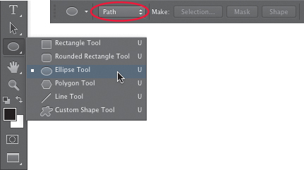
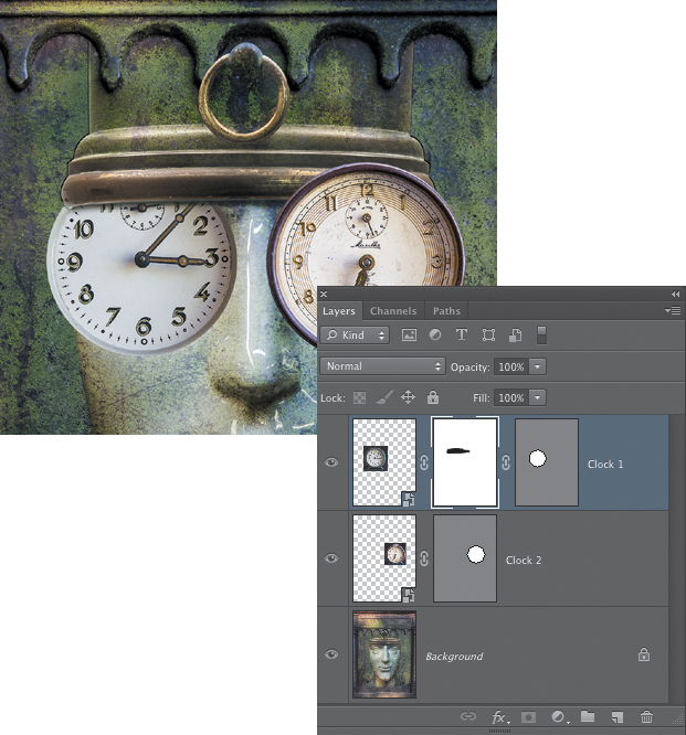
1. In the Tools panel, select the Ellipse tool. This tool is grouped with the other vector Shape tools just above the Hand tool (FIGURE 9.55). In the Options bar for the Ellipse tool, click the drop-down menu on the far left and set it to Path (if you’re using Photoshop CS5, there is no menu for this choice, but there are three icons in the same place that offer the same options; choose the second icon to create a path). Position the cursor over the center point of the Clock 1 face. The same shortcuts for drawing a selection from the center of the origin point and for constraining it to a circle will also work for this tool. Press Option+Shift (Alt+Shift) and click and drag outward to begin the ellipse path. The goal is to create a path that includes the center flat part of the clock face just to the edge of the slanted bevel (that is, the path should include all of the markings on the clock face but stop just beyond them), as shown in FIGURE 9.56. Don’t worry if the ellipse shape is not exactly as you want it to be; you can fix that later.
Figure 9.55. Use the Ellipse tool and the setting in the Options bar to create a path from any shape you draw with it.
Figure 9.56. The actual path may not display well in these illustrations, so we’ve added a red circle to show the approximate position of the path.
2. In the Paths panel, you’ll see a new entry labeled Work Path. Double-click it and name it, or just use the default name of Path 1 (FIGURE 9.57). A Work Path is a temporary state of a path in progress, so it’s always good to double-click on it in the Paths panel and “promote” it to a regular path with a name. If the size and position of the path is not exactly as you want it, don’t worry about that at this point; you’ll be able to easily adjust the path once it has been turned into a vector mask.
Figure 9.57. When a path is first created, Photoshop refers to it as a Work Path. Double-click the path, name it, and promote it to a regular path.
Turning a path into a vector mask
Now it’s time to add a vector mask based on the path.
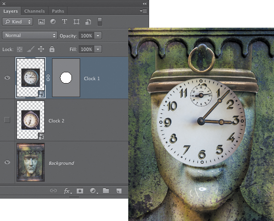
1. Make sure that the path is still the active item in the Paths panel and that the blue, Clock 1 layer is active in the Layers panel. From the main menu, choose Layer > Vector Mask > Current Path. A vector mask is added to the active layer. The areas inside the path are visible, and the areas outside it are hidden (FIGURE 9.58). Click in the area below the path in the Paths panel to make sure it is not active before you continue with the next step.
Figure 9.58. A vector mask is added to the Clock 1 layer.
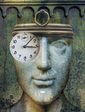
2. With the Clock 1 layer active, choose Edit > Free Transform and scale the clock smaller, as shown in FIGURE 9.59. Hold down the Shift key as you drag inward on a corner handle to constrain the aspect ratio. Press Return (Enter) when you’re done to apply the transformation. Then use the Move tool to move the clock into position over the eye on the left side of the image.
Figure 9.59. The Clock 1 layer scaled smaller and repositioned.
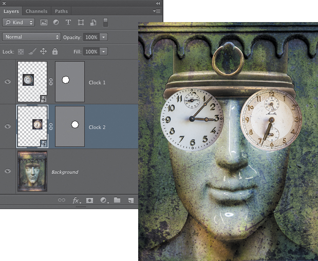
3. Turn off the visibility for the Clock 1 layer and turn on the visibility for the Clock 2 layer. Make this layer active and repeat the procedure from the previous steps to create a circular path around the inner face of the brown Clock 2 layer (similar to the area you selected on Clock 1), turn it into a vector mask, and then scale the clock layer smaller and reposition it over the eye on the right side of the image (FIGURE 9.60).
Figure 9.60. After vector masks are added to the two clock layers, they are scaled smaller and positioned over the eyes of the face.
Editing a vector mask
A vector mask can be edited using the same tools and techniques that you use to edit a path made by the Pen tool. We cover the details of more customized path editing in the web-based chapter, “Pen Tool Power.” In this section we’ll apply simple transformations to fine-tune the shape of one of the vector masks using the Free Transform Path command. In the version shown here, the vector mask for the brown clock is not centered as well as it could be. To transform the path in the vector mask but not the layer, however, you need to make sure that the vector mask is active.
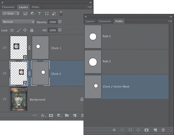
1. Click on the Clock 2 layer to make it active. Then click on the thumbnail of the vector mask to activate it. In the Paths panel you can check to see that the thumbnail for the vector mask is active (FIGURE 9.61).
Figure 9.61. A highlight border around the vector mask thumbnail and the highlighted vector mask in the Paths panel both indicate that the vector mask is the active item.
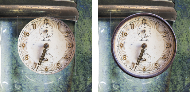
2. Press Command+T (Ctrl+T) to switch to Free Transform mode (Edit > Free Transform Path). For the version we made, we first centered the path better over the clock face and then decided to press Shift+Option (Shift+Alt) and drag on a corner handle to scale it larger from the center point. This showed a bit of the clock casing and suggested a rim to this lens of the “glasses” (FIGURE 9.62). We also transformed the vector mask of the blue Clock 1 layer and expanded it to include the inner beveled rim of the clock face (FIGURE 9.63).
Figure 9.62. Transforming just the path of the vector mask, not the actual layer.
Figure 9.63. The vector mask for the blue Clock 1 layer is also adjusted to show more of the inner bevel.
Combining a vector mask and a pixel mask
A vector mask is ideal for image elements that naturally have hard, smooth, and often curved edges, such as the clocks in the “Time Keeper” composite. However, for some composite scenarios, you may need masking that has hard and soft characteristics in the mask edges. For this image, we’ll add a pixel layer mask to each clock layer and edit it with the Brush tools to suggest that the top edge of the glasses are beneath the rim of the metal fixture at the top of the head.
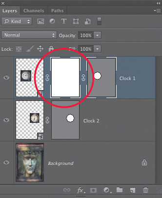
1. Make the Clock 1 layer active and click the Add layer mask icon at the bottom of the Layers panel. This adds a pixel layer mask to the layer in addition to the vector mask (FIGURE 9.64). For the rest of the chapter, we’ll refer to a pixel layer mask simply as a layer mask.
Figure 9.64. A pixel layer mask is added to the layer in addition to the vector mask.
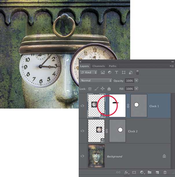
2. Select the Brush tool (B) and set the foreground color to black. Choose a soft-edged brush of an appropriate size (our brush was 70 pixels). With the layer mask active (click on its thumbnail to make sure), paint with black to hide the top edge of the clock and make it appear as if it is just under the brim of the metal “hat.” To quickly paint a straight brush stroke along the entire edge of the hat, click once where you want to begin and then Shift-click at the end. A brush stroke will be drawn between the two click points (FIGURE 9.65). Once you have most of the metal edge painted in, try lowering the brush opacity to about 30% and brushing a bit over the actual top part of the clock. This can help add the sense of some shading along the top part of the clock “lenses.”
Figure 9.65. Painting on the layer mask with black to hide the top part of the clock and make it appear to be under the metal edge.
When a mask is active, pressing D will set the default colors, which places white in the foreground and black in the background. You can then press X to exchange the colors.
Transforming a layer separately from its mask
In the version shown in Figure 9.65, the size of the clock face was a bit too large to look as if it were under the entire front edge of the metal hat. To fix this, we needed to scale the clock smaller, but not the layer mask. To do this, we first clicked the chain link icon between the layer and layer mask thumbnail to unlink the layer from the mask (the vector mask is still linked). Then we clicked on the layer thumbnail to make sure it was active and used the Free Transform command (Command+T [Ctrl+T]) to scale the clock layer smaller (FIGURE 9.66). Because the layer mask was not linked to the layer, it stayed in place where it needed to be to hide the top part of the clock under the metal edge.
Figure 9.66. Scaling the layer independently of the layer mask made it fit better under the metal edge.
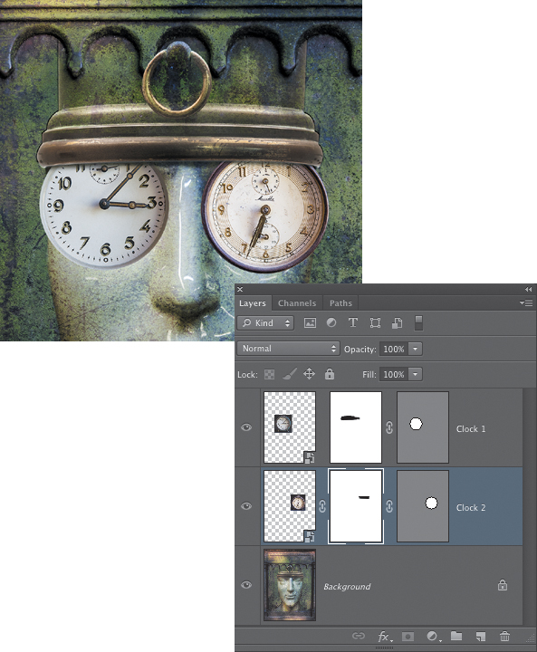
1. Make the Clock 2 layer active and use the Free Transform command to scale that a bit smaller to match the resized clock on the other side. Because a layer mask has not been added yet, you don’t have to unlink anything. In this case you want the vector mask and the layer to be transformed together.
2. Add a layer mask and paint with black on the mask to hide the top part of the clock as you did with the blue Clock 1 layer (FIGURE 9.67).
Figure 9.67. The second clock layer is scaled smaller, and a layer mask is added to hide the top part of the clock “under” the metal edge.
Fine-tuning with Layer Styles
For the final steps in this composite exercise, you’ll bring in the clock gears image to create a bridge between the two clock “lenses.” Then you’ll use some simple Layer Styles to add depth to the image.
1. Make the Background layer active, and then bring the clock gear image into the main composite. Double-click the name for the layer and rename it Gear Bridge.
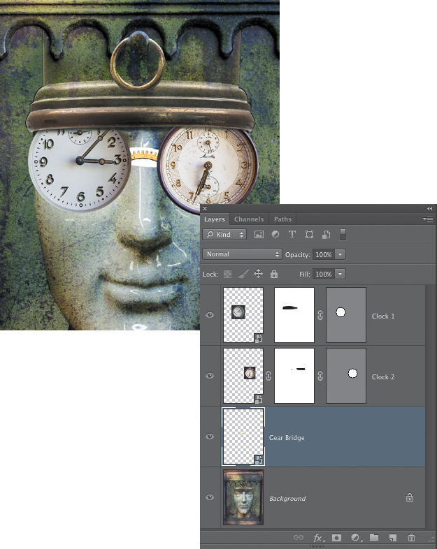
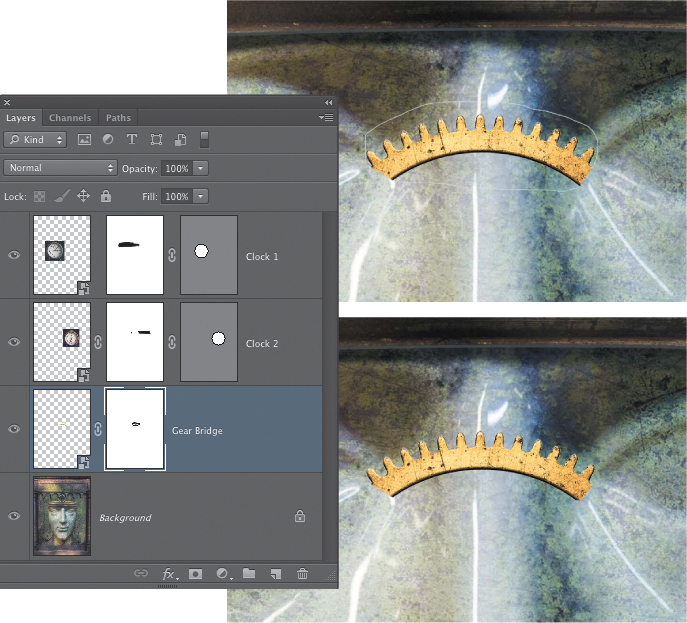
2. You’ll use the gear to create a bridge for the glasses. Making the Background layer active before adding the gear image ensures that the gear will appear below the two clock layers. The clock gear is too large and needs to be scaled smaller. Turn the gear layer into a Smart Object by Control-clicking (right-clicking) on the layer in the Layers panel and choosing Convert to Smart Object. Then use the Free Transform command (Edit > Free Transform) to scale it smaller until it looks about the right size for the bridge between the two lenses (FIGURE 9.68).
Figure 9.68. The clock gear is added as a new layer and scaled smaller to create a bridge for the glasses.
The white background needs to be masked. Although the Multiply blending mode will hide the white areas of the layer, it will not work in this case because it also dulls the brass surface of the gear too much. The Blend If sliders are also an option to explore anytime you have a white background you want to hide. But for this particular layer, they are not ideal. Instead you’ll use a simple selection made via the Color Range command.
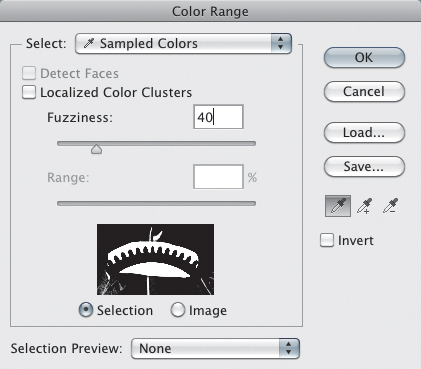
3. Turn off the visibility of the two clock layers by clicking their eye icons. Because the area of the Gear Bridge layer you need to select is pretty small, use the Rectangular Marquee tool to make a pre-selection of just the actual image area of that layer. This preselection will restrict the results of Color Range (and the preview) to only the selected areas. Choose Select > Color Range. Use the Eyedropper tool in the Color Range dialog to sample the white area. The default Fuzziness setting of 40 should work fine for selecting the white areas (FIGURE 9.69). Click OK to create the selection.
Figure 9.69. The Color Range dialog for selecting the white areas of the Gear Bridge layer.
4. With the selection active in the image and the Gear Bridge layer active, Option-click (Alt-click) the Add layer mask icon at the bottom of the Layers panel to add a layer mask that hides the selected area. Some white fringes may still be visible. If so, use the Brush tool with a small-sized brush and paint with black on the layer mask to hide any straggler white areas that should not be showing (FIGURE 9.70). If the edges still look a bit hard and rough, in the Properties panel for the layer mask, set the Feather slider to 1 pixel.
Figure 9.70. Touching up the layer mask for the Gear Bridge layer hides any stray fringes that may still be visible from the initial Color Range selection.
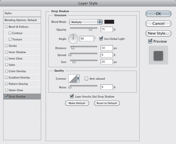
5. Turn on the visibility for both clock layers. Make the Clock 2 layer active, click the Layer Styles button at the bottom of the Layers panel, and choose Drop Shadow. For the shadow in this example, we set the Angle to 90 degrees, the Distance to 10, and the Size to 20 (FIGURE 9.71).
Figure 9.71. The Drop Shadow settings in the Layer Style dialog.
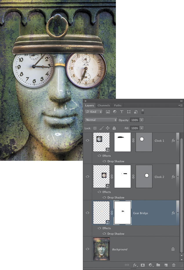
6. Control-click (right-click) on the Clock 2 layer in the Layers panel and choose Copy Layer Style (the same command is available by choosing Layer > Copy Layer Style). Click on the other Clock 1 layer, and then Control-click (right-click) on it and choose Paste Layer Style to copy the same settings to that layer. Do the same for the Gear Bridge layer to copy the drop shadow to that layer (FIGURE 9.72). After you add the drop shadow to the Gear Bridge layer, you may notice some residual white fringing along the lower edge of the gear. If so, click the layer mask for that layer to make it active and paint with black using a small, hard-edged brush to carefully mask out any visible white edges.
Figure 9.72. A Drop Shadow layer style added to all of the layers that form the “eyeglass” creates a more convincing effect.
Summarizing the vector mask exercise
As with several of the exercises in this chapter, this tutorial included several different techniques that have already been introduced in other chapters. You began by using the Ellipse vector shape tool to create a simple path of a basic geometric shape. The path for each clock layer was then turned into a vector mask, creating a hard and smooth edge. A pixel layer mask was added to each layer to further modify the effect and create the appearance that the tops of the clocks were underneath the metal edge of the hat. You also learned how to transform a layer separately from its layer mask. Finally, you added Drop Shadow layer styles to add depth and believability to the effect that the clock glasses are sitting on the face (FIGURE 9.73).
Figure 9.73. The final version of the “Time Keeper” composite.
Layer Mask Essentials
From the tutorials already featured in this chapter, you’ve learned that layer masks are a powerful tool for making multiple image composites. They allow you to flexibly and nondestructively hide and show parts of a layer with great precision and accuracy, or with just the right amount of gradual transition to create a smooth fade from one image to another. In this section we’ll look at the other aspects of working with layer masks that allow you to change the appearance of the mask for editing, turn a layer mask into a selection, and temporarily disable a mask so that it does not affect the image.
Viewing Layer Masks
To see a black-and-white view of a layer mask in the main document window, Option-click (Alt-click) on the thumbnail of the mask in the Layers panel. Repeat the shortcut (FIGURE 9.74) to switch back to the normal view of the image.
Figure 9.74. Option-click (Alt-click) the thumbnail of a layer mask to see the black-and-white view in the main document window.
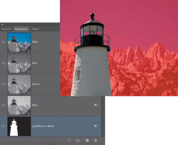
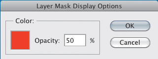
To see the mask represented as a semitransparent colored overlay, press the Backslash () key. You can also access this view by clicking the eye icon for the mask in the Channels panel as you are viewing the main RGB channels in the images (FIGURE 9.75). This view of the mask can be useful when you need to make edits that require you to see the mask and the actual image at the same time. The default color for the overlay is red. To change the color of the overlay, Control-click (right-click) on the thumbnail of the layer mask and choose Mask Options. Here you can set the opacity for the colored overlay and click in the color swatch if you need to choose a color that works better with the colors in the image (FIGURE 9.76).
Figure 9.75. Pressing the Backslash () key displays the mask as a semitransparent colored overlay.
Figure 9.76. The Layer Mask Display Options dialog.
Turning a Layer Mask into a Selection
Layer masks can be turned into an active selection. Just like alpha channels, white areas in the mask will be fully selected and black areas will not be selected. Areas that are gray will be partially selected. The lighter the tone of gray, the more selected that area will be; the darker the gray, the less selected it will be.
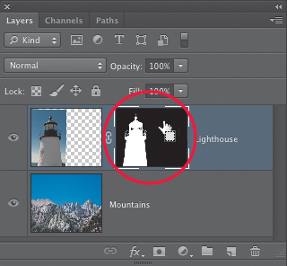
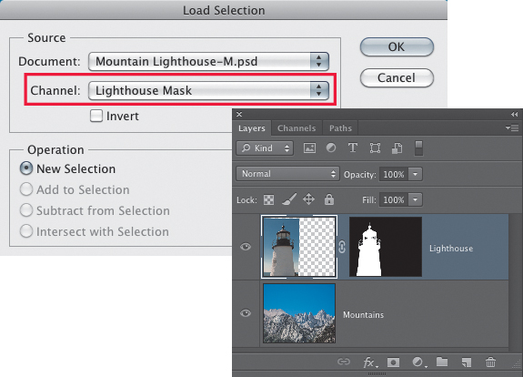
To load a layer mask as a new selection, Command-click (Ctrl-click) on the thumbnail of the layer mask in the Layers panel (FIGURE 9.77). If you prefer to use the menus to load a selection, make sure the layer with the layer mask you want to select is active in the Layers panel and choose Select > Load Selection. In the Load Selection dialog, the mask for the active layer will appear as a choice in the drop-down Channel menu (FIGURE 9.78).
Figure 9.77. By Command-clicking (Ctrl-clicking) on the thumbnail of a layer mask, you can turn it into a selection.
Figure 9.78. When a layer with a layer mask is active in the Layers panel, the option to load a selection from the layer mask is available in the Load Selection dialog.
Once you’ve turned a layer mask into a selection, you can apply the same layer mask to a different layer. With the selection active, activate the layer you want to mask and click the Add layer mask icon at the bottom of the Layers panel. Alternately, you can choose Layer > Layer Mask and then either Reveal Selection or Hide Selection depending on how you want the mask to affect the layer.
Moving and Copying a Layer Mask to Another Layer
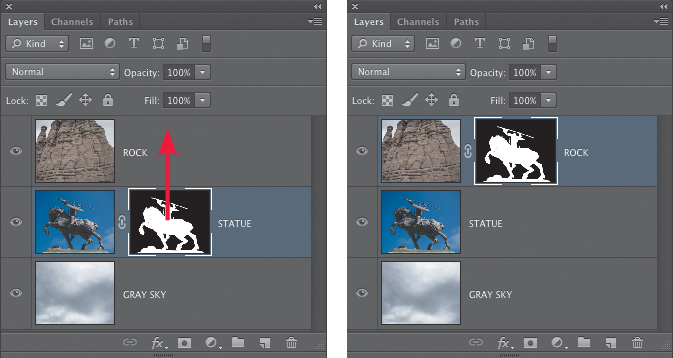
If you have a layer mask attached to one layer and you need to move it to another layer, drag the layer mask thumbnail to the layer where you want to move it (FIGURE 9.79). Using this procedure with an adjustment layer as the target layer will result in a dialog asking if you want to replace the existing layer mask that is part of the adjustment layer (and in most cases, you would click Yes to this question).
Figure 9.79. Moving a layer mask from one layer to another.
Making a copy of a layer mask by first turning it into a selection and then adding a new mask based on that selection to another layer is another way to create a copy of a layer mask.
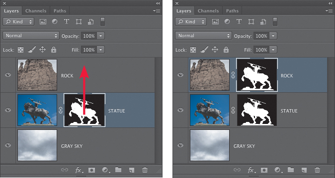
If all you need to do is copy a layer mask from one layer to another, there is a very easy way to do this. Hold down the Option (Alt) key and drag a layer mask thumbnail to the layer where you want to copy it. When you release the mouse button, the layer mask will be copied to the new layer (FIGURE 9.80). If you run into problems with this operation, just remember that you must press the modifier key before you click and drag on the layer mask thumbnail.
Figure 9.80. Copying a layer mask from one layer to another.
Disable/Enable a Layer Mask
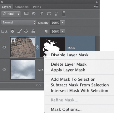
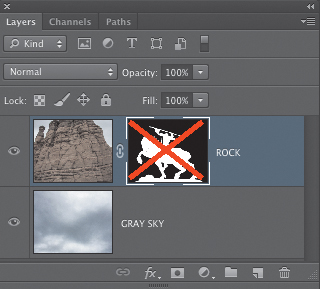
To temporarily turn off a layer mask so it doesn’t affect the image, choose Layer > Layer Mask > Disable. You can also do this by Control-clicking (right-clicking) on the thumbnail of the layer mask in the Layers panel (FIGURE 9.81). A faster way is to Shift-click on the thumbnail of the layer mask. A red X will appear over the thumbnail, indicating that the mask is temporarily disabled (FIGURE 9.82). To turn the mask back on, Shift-click the thumbnail again, or choose Layer > Layer Mask > Enable (also available by Control-clicking (right-clicking) on the thumbnail of the layer mask).
Figure 9.81. Control-click (right-click) on the thumbnail of the layer mask to access a context menu with additional options, including disabling the mask.
Figure 9.82. When a layer mask is disabled, a red X appears over the thumbnail of the mask in the Layers panel.
Linking and Unlinking Layer Masks
Just as layers can be linked together, layer masks can also be linked or unlinked from the layer they are associated with. You’ve already taken advantage of the ability to unlink a layer from its mask earlier in the “Time Keeper” composite exercise. In most cases, when you add a layer mask to a layer, the default behavior is for the mask to be linked to the layer. This is true whether a selection is active or not. (However, there is an exception to this rule, and we’ll get to that in a bit.) This means that when you move the layer with the Move tool, the mask will move with it. A small chain link icon between the layer thumbnail and the mask thumbnail indicates that the two are linked together. To unlink a layer mask from the layer, click the chain link icon and it will disappear, indicating that the mask and the layer are no longer linked (FIGURE 9.83).
Figure 9.83. When a layer mask is linked to a layer, a chain link icon appears between the thumbnails. Click the chain link icon to unlink the mask from the layer.
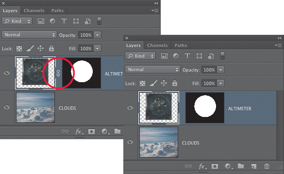
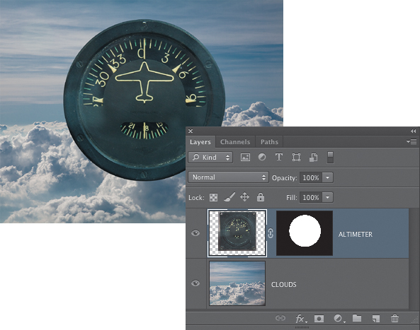
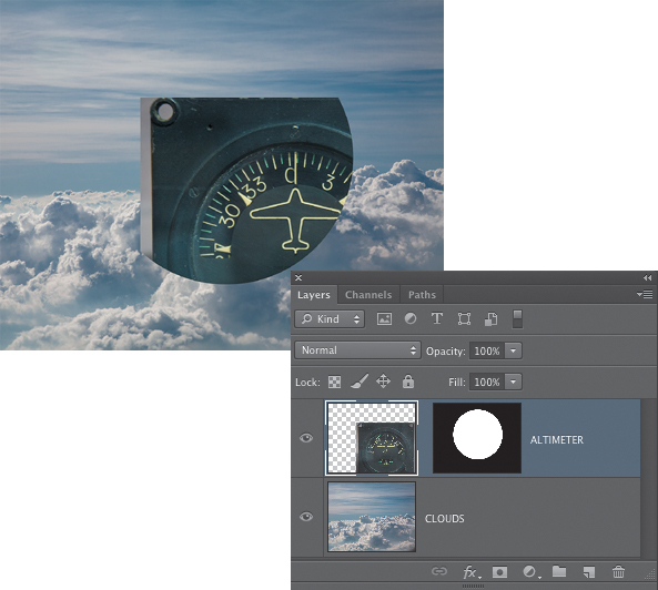
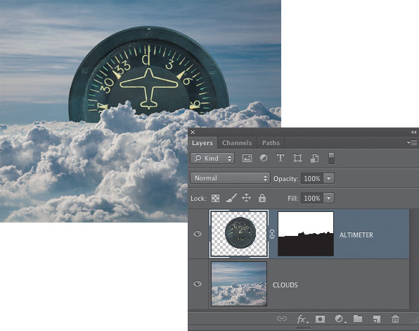
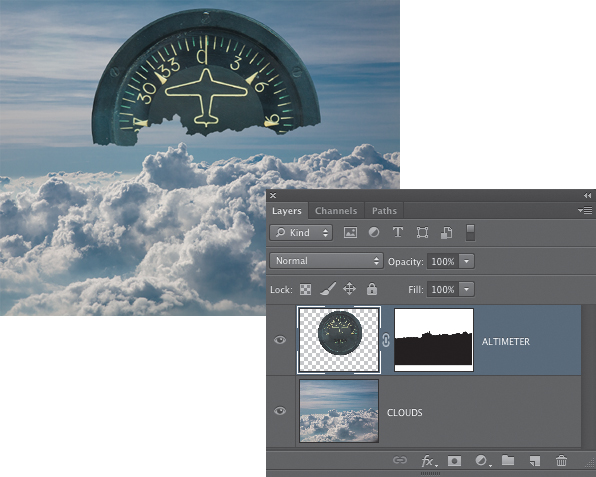
In many compositing situations, having the mask linked to the layer will make the most sense. For example, the altimeter in FIGURE 9.84 is linked to its layer mask, so it can be moved anywhere in the composite and its mask moves with it, preserving the precise circular outline of the gauge. However, when the mask is unlinked, the mask stays in place while the layer is moved. But in this case the mask needs to stay aligned with the circular shape of the altimeter for it to work (FIGURE 9.85).
Figure 9.84. The altimeter is linked to its layer mask, and when the layer is moved, the mask moves with it.
Figure 9.85. When the altimeter layer is unlinked from its layer mask, the layer can be moved but the mask stays in place, breaking the illusion that the mask was creating.
For any compositing scenario where an object, such as the altimeter in the previous example, is meant to be independent of the background elements, having it linked to its layer mask makes sense. When the layer mask is linked to the layer, they function as a single unit. But for a composite in which one of the elements needs to interact with a background element, having a layer mask that is unlinked may be the best way to deal with that situation.
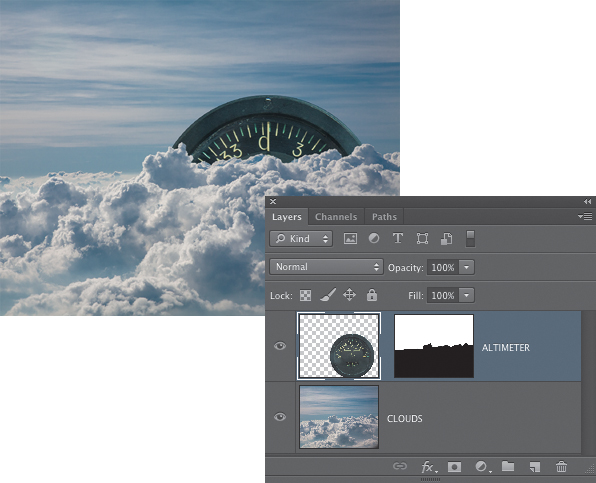
Let’s consider an alternate version of the altimeter composite. In the version shown in FIGURE 9.86, the altimeter is a circular object surrounded by transparency, and a layer mask has been added to it to make it appear as if it is partially behind the clouds. When the altimeter layer is moved, its linked layer mask moves with it, destroying the effect that the lower half was covered by the clouds (FIGURE 9.87). However, when the layer mask is unlinked from the layer, the layer can be moved anywhere in the composite and it will always be covered by the clouds that are in the lower half of the image (FIGURE 9.88). For this type of composite, having the altimeter layer mask unlinked from the layer makes the most sense.
Figure 9.86. In this example, a layer mask makes it appear as if the altimeter is behind the clouds.
Figure 9.87. When the altimeter layer is moved, a linked layer mask moves with it, destroying the illusion that it is behind the distant clouds.
Figure 9.88. When the layer is unlinked from the layer mask, the altimeter will always appear to be behind the clouds, no matter where in the composite it is placed.
Paste Into
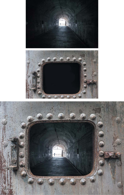
One very useful way to copy an element from one file and paste it into another file in a specific location is to use the Paste Into command. When you have a selection in a file and you choose File > Paste Special > Paste Into, Photoshop creates an unlinked layer mask based on the selection that reveals the pasted element only in the areas that were selected. Because the mask is unlinked, you can move the layer freely and the mask will remain in its original position. This technique is ideal when you want to add a new view to a doorway or window, or put a new scene in a picture frame. We’ll explore this concept by adding a new image that will appear within the opening of a metal hatch (FIGURE 9.89).
© SD
Figure 9.89. The metal hatch, tunnel view, and the final composite created using the Paste Into command.
![]() ch9_metal_hatch.psd
ch9_metal_hatch.psd
ch9_tunnel.jpg
1. Open the metal hatch and tunnel files in Photoshop. In the tunnel image, choose Select > All and then choose Edit > Copy. The shortcuts are Command+A (Ctrl+A) and Command+C (Ctrl+C).
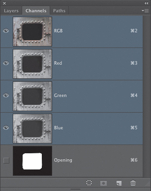
2. Switch back to the metal hatch image. This file already has an alpha channel defining the interior areas of the hatch. Load this as a selection by Command-clicking (Ctrl-clicking) on the thumbnail of the alpha channel (FIGURE 9.90).
Figure 9.90. The alpha channel for creating a selection of the metal hatch opening.
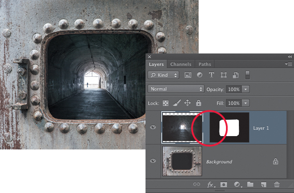
3. Choose File > Paste Special > Paste Into. If you’re good at using two-handed shortcuts, you can press Shift+Command+Option+V (Shift+Ctrl+Alt+V). The tunnel image will be added as a new layer with an unlinked layer mask showing the tunnel only inside the opening of the hatch. The tunnel layer will be active, and you can use the Move tool to reposition it and experiment with different placements (FIGURE 9.91).
Figure 9.91. The Paste Into command creates a new layer with an unlinked layer mask based on the selection of the hatch opening.
Two other options are also in the Paste Special menu. However, for most compositing work, we feel that neither is as useful as Paste Into. Still, for some situations, they may be just what you need:
• Paste Around will do the opposite of what Paste Into does. It will create an unlinked layer mask based on the active selection that hides the newly pasted layer in the selected areas, showing it only in the parts of the image that were not selected. As the name implies, it pastes the copied data around the active selection instead of inside it.
• Paste in Place may appear to be no different than a regular Paste, but there is a key difference that may be critical for some operations. When you choose Edit > Paste, if the copied element is smaller than the file where you are pasting in, it is centered in the file. But if it is larger, Photoshop will align the top-left corner of the pasted item with top-left corner of the file where you are placing it. When you choose Paste in Place, it will align the exact center of the pasted item with the exact center of the destination file.
Applying a Layer Mask
If this chapter was an old pirate treasure map, it is at this point where you would see the warning, “Here there be dragons!” We’re not talking about real dragons, of course, or even a pixelated equivalent, but metaphorical dragons in the form of a potentially destructive operation.
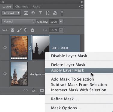
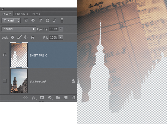
The Apply Layer Mask command is in two places in Photoshop: To access it, you can choose Layer > Layer Mask > Apply or Control-click (right-click) on the thumbnail of a layer mask in the Layers panel and choose Apply Layer Mask (FIGURE 9.92). Choosing this command will make the effect of the layer mask permanent by deleting the hidden, masked pixels and leaving only those that were visible when the mask was in place. Using the example of the Dresden sheet music composite from earlier in this chapter, you can see that applying the layer mask on the Sheet Music layer throws away all of the masked pixels (FIGURE 9.93). This means that this layer can never be repositioned because it would no longer match the intricate edges of the buildings.
Figure 9.92. The Apply Layer Mask command removes the mask and permanently deletes the masked pixels.
Figure 9.93. With the visibility of the Background layer turned off, this illustration shows how the Apply Layer Mask command has deleted pixels from the Sheet Music layer.
We generally don’t like to delete pixels from a masked layer, mainly because if the mask was not perfect, we’ve lost the ability to go back and fine-tune the edges. Although the History panel may provide you with the ability to recover from applying the layer mask should you need to (depending on how many history states are being recorded, that is), once you save and close the file, there is no going back. For that reason, we counsel you to use this command with caution and only when you know that there is no reason to keep the layer mask.
You will also see the Apply Layer Mask message dialog when you drag a layer mask thumbnail to the trash can icon at the bottom of the Layers panel. The safe approach is always to delete the mask and not apply it.
Refining Layer Masks
Just as selections often require modifications or editing before they are ready to be used, layer masks may also need to be finessed, fine-tuned, improved, modified, and refined. Fortunately, there are many ways to do this. The type of refinement method you choose depends on how the mask needs to be modified. In this section we’ll look at some of the most important techniques for editing layer masks.
The Properties Panel
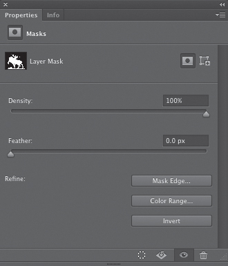
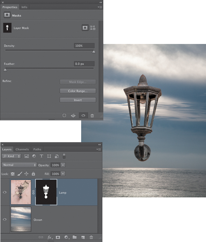
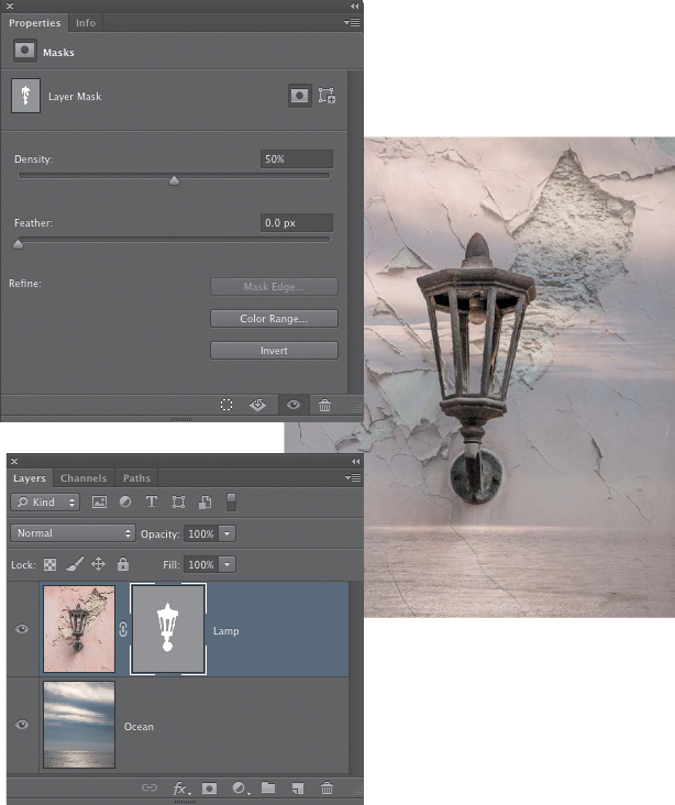
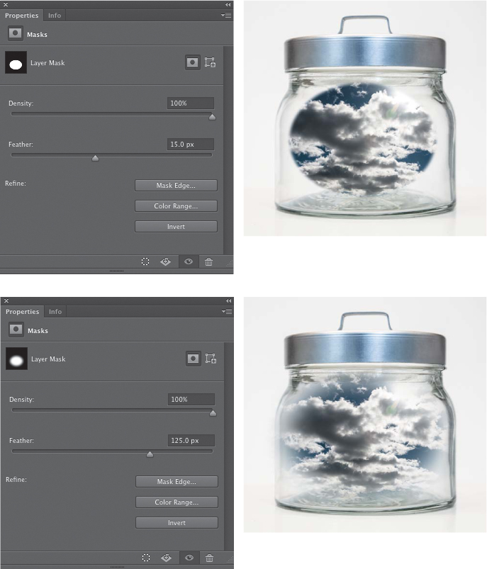
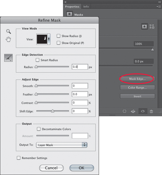
The first stop for refining your layer mask will most likely be the Properties panel. The Properties panel is a new addition to Photoshop CS6, but it really is just a renaming and reorganizing of functionality that has been in Photoshop since CS4, combining the Adjustments and Masks panel into a single panel.
The available options in the Properties panel will vary depending on what aspect of a layer is currently active. When a regular layer with no layer mask is active, no properties will be displayed. When an adjustment layer is active, such as a Curves, Levels, or Hue/Saturation layer, this is where you can adjust the settings for that adjustment. Two buttons on the top left let you switch between the adjustment controls and the layer mask (FIGURE 9.94). If a layer mask is active, either on an adjustment layer or a pixel layer, you have access to several useful controls for modifying the mask, including buttons to make the layer mask active if it is not currently active or to add a vector mask (FIGURE 9.95).
Figure 9.94. When an adjustment layer is active, the Properties panel contains controls for modifying the adjustment. Buttons in the top left let you switch between the adjustment properties and the mask properties.
Figure 9.95. When a layer mask is active, the Properties panel contains controls for modifying the mask. Buttons in the top right let you activate the mask if it is not already active or add a vector mask.
Density
The Density slider controls the density of the black tones in the mask and allows you to create effects where parts of the image show at full opacity (those areas that are white in the mask) while other areas are only partially visible, letting some of the underlying layers show through. With a setting of 100% density, black areas in the layer mask are totally black (FIGURE 9.96). When the setting is lowered, the black tones in the mask gradually become lighter. If you recall that black in a mask hides the layer, white shows it at full strength, and gray partially shows it, this will give you some insight into how the Density slider will affect the visibility of the layer. The lower the density setting, the more “transparent” the black areas of the mask become, allowing parts of the active layer to show through in combination with whatever is on the layers underneath (FIGURE 9.97). The Density slider is nondestructive and can be changed at anytime. The one issue with the Density slider is that it affects the tonality of only the blacks, not the whites.
© SD
Figure 9.96. When the layer mask Density is set to 100%, black tones in the mask are totally black and hide those areas of the layer.
Figure 9.97. As layer mask Density is lowered, black tones in the mask become progressively lighter, allowing more of those parts of the layer hidden by the black mask to show through in the composite image.
A similar slider that controls the density of the whites would be incredibly useful (hint, hint, Adobe!). Fortunately, we have a workaround for that using Levels and Curves to modify a mask. You’ll learn about this later in the section “Modifying Masks with Levels and Curves.”
Feather
The Feather slider lets you soften the edges of a layer mask. Like the Density slider, it is a nondestructive adjustment and you can unfeather a mask even after it has been softened significantly. Use a low setting of one or two pixels to slightly soften the edges when a mask just looks a bit too sharp and “cut out.” Increasing the Feather value creates more noticeable softening while still preserving the basic shape of the mask, and at higher settings the mask edges will blur completely so there are no distinct edges at all (FIGURE 9.98).
© SD
Figure 9.98. A Feather value of 15 pixels applies a slight yet noticeable softening to the edges of the oval layer mask on the Cloud layer. Increasing the value to 125 pixels removes any obvious edge and creates the appearance that the clouds are suspended inside the jar.
Refine Mask
In the lower-right section of the Properties panel are three buttons that offer additional ways to modify a layer mask. The first is the Mask Edge button. Clicking this button takes you to the Refine Mask dialog (FIGURE 9.99). If this looks familiar to you, it should; it is the same as the Refine Edge dialog, which we explored in great detail in Chapter 7. The only difference is that Refine Edge is for refining the edges of an active selection, and Refine Mask is for refining the edges of a layer mask.
Figure 9.99. Clicking the Mask Edge button in the mask Properties panel brings up the Refine Mask dialog, an identical twin to the Refine Edge dialog, which is used to modify selections.
For a quick review of the Refine Edge/Refine Mask dialogs, we’ll add a clock tower behind the walls of an old fort and use the Refine Mask controls to improve the layer mask for the clock tower (FIGURE 9.100).
© SD
Figure 9.100. The two source photos, and the final composite of the clock tower and the fort images.
![]() ch9_fort.jpg
ch9_fort.jpg
ch9_clocktower.jpg
1. Open both images in Photoshop and drag the clock tower photo into the fort image. With the Tower layer active, use the Quick Selection tool to make a selection of the tower. Don’t worry if the selection does not include the weathervane at the top of the tower. With the selection active, click the Add layer mask icon at the bottom of the Layers panel (FIGURE 9.101).
Figure 9.101. The layer mask added to the Tower layer.
2. The selection made by the Quick Selection tool and the layer mask created from it are probably pretty good. The one element that may not be included is the delicate weathervane at the top of the tower (FIGURE 9.102). Fortunately, this is easily fixed with the Refine Mask dialog.
Figure 9.102. Because the weathervane atop the tower was not included in the initial selection made by the Quick Selection tool, the layer mask created from that selection is masking that part of the tower.
3. Click the Mask Edge button in the Properties panel to bring up the Refine Mask dialog. Open the View menu at the top and choose Overlay (V). This is a useful view because you can see the mask represented as a red transparent overlay and the image at the same time. Other useful views are Black & White view (K), which shows a mask view, and On Layers (L), which shows the composite view. The On Layers view is useful at the end of the process to check to see how well the edge refinements are working. We’ll be switching back and forth between these three views to inspect the changes in the mask (FIGURE 9.103). In the Edge Detection section, select Smart Radius and set the Radius to 2 pixels. Just to the left of this area you’ll see a brush tool icon that is already selected. This is the Refine Radius tool, and you can use it to tell Photoshop where it needs to refine the edges of the mask (FIGURE 9.104).
Figure 9.103. Overlay and Black & White views are useful when editing a mask in the Refine Mask dialog.
Figure 9.104. The Refine Radius tool and the Edge Detection settings.
4. Zoom in to a 100% view so you can see a close-up view of the top of the tower (View > Actual Pixels). Move the cursor over the image and adjust the brush size by tapping the left bracket key (smaller) or right bracket key (larger) until you have a brush size that is a good fit for the top of the tower. For our work on this example image, we used a 25-pixel brush (you can see the brush size and change it in the Options bar). Paint over the very top of the tower where you know the weathervane is. Press K to switch to the Black & White view to see the result (FIGURE 9.105).
Figure 9.105. Initial edits with the Refine Radius tool reveal a little more of the weathervane.
5. If the outline of the weathervane is still a bit faint, try raising the Radius to 6 pixels and paint over that area again with the Refine Radius tool. In addition to viewing it in the Black & White view (K), you can also switch to the On Layers view (L) to see how well the weathervane will show up in the composite image (FIGURE 9.106). When you’re satisfied with the result, click OK and the layer mask will be updated with the changes.
Figure 9.106. Further edits with the Refine Radius tool and a higher Radius setting result in more of the weathervane showing in the mask.
If you feel that not all of the weathervane is showing after performing these edits with the Refine Mask dialog, you have two possible ways to deal with this (actually, because you’re using Photoshop, there are probably more than that, but we’ll delve into only a couple of them). The first way is to zoom in closely and use a very small brush to edit the layer mask, painting over the weathervane area with white to reveal the parts that are still not showing. This is slow and tedious work, but it will get the job done. You may need to go back and forth between painting with white and black until you get it just right. Or, you could take an easier route and take advantage of the power of blending modes.
To fix the weathervane in this example image, we made a loose selection of just the weathervane using the Lasso tool with a Feather value of zero. Then, making sure that the actual Tower layer was active (not the layer mask), we pressed Command+J (Ctrl+J) to copy the selected area to a new layer. We set the blending mode for this layer to Darken to reveal anything that was darker. Because the underlying sky is darker than the original sky, the lighter sky from the original image does not show, and more of the dark weathervane is visible (FIGURE 9.107).
Figure 9.107. The first image shows the weathervane after the edits in the Refine Mask dialog. The second image shows the results of copying a selection of the weathervane to a new layer and setting the blending mode to Darken.
Next, we copied this layer again by pressing Command+J (Ctrl+J). For this second copy of the Weathervane layer, we set the blending mode to Pin Light to allow the bright golden highlights to show through (FIGURE 9.108). To prevent the accidental movement of the three layers that now made up the tower, we selected them all in the Layers panel and clicked the chain link icon at the bottom of the Layers panel to link them together (FIGURE 9.109).
Figure 9.108. A second copy of the Weathervane layer is made and the blending mode is set to Pin Light, which brings back the bright highlights on the polished brass surface.
Figure 9.109. The Tower layer and the two Weathervane layers are linked to ensure that they remain aligned together.
As a final edit to this image, we made a copy of the Background layer and the used the Polygonal Lasso tool to make a selection of the fort wall. With this selection active, we added a layer mask to the Fort Wall layer. Then we moved the new Fort Wall layer above the three layers that made up the clock tower. Although we could have edited the Tower layer mask to make it appear that the tower was behind the wall, we wouldn’t have been able to move the tower once the mask had been edited to conform to a specific part of the wall. With a separate Fort Wall layer above the Tower layers, the tower can be repositioned at anytime (FIGURE 9.110). Spending some time thinking ahead to figure out what is the most flexible way to configure the layers in a composite is time well spent!
Figure 9.110. The final composite and the Layers panel.
We’ve only scratched the surface of what you can do with the Refine Mask dialog. But the Smart Radius and Refine Radius tools are two of the most useful features in this dialog, and for many masks edits, you may find they are all you’ll need. For a more detailed rundown on what the rest of the controls in this dialog do, refer to the “Refine Edge” section in Chapter 7.
Color Range
The Color Range button takes you directly to the Color Range dialog, which you can also access via the Select menu. The Color Range command was also covered in detail in Chapter 7, so we won’t repeat that coverage here. Accessing Color Range from the Properties panel is best done when you have added a blank layer mask or are beginning with a simple mask and want to customize it to the image using the Color Range dialog functionality (FIGURE 9.111). When the Color Range dialog appears, you can click on the area in the image that you want to reveal in the mask, and then adjust the Fuzziness slider or Shift-click to add more areas to the mask, as shown in FIGURE 9.112.
Figure 9.111. Accessing Color Range from the Properties panel with a black layer mask active.
Figure 9.112. Using Color Range on an active layer mask replaces any previous mask with a new version based on the Color Range settings.
It really doesn’t make much sense to use this technique to edit a layer mask that is already set up the way you want because accessing Color Range via the Properties panel will replace any existing mask with whatever changes you make in the Color Range dialog. This may be exactly what you need to do, but just be aware that if you already have an intricate, precise, and mostly accurate layer mask, clicking the Color Range button will essentially reset the mask. The preview you see in the Color Range dialog is what the new mask will be, and clicking OK in the Color Range dialog will eliminate all the work you’ve done previously.
Invert
Invert is the simplest feature in the mask Properties panel. Clicking this button inverts the tones in the mask, turning black to white and white to black. To invoke the Invert command, you can press Command+I (Ctrl+I) or choose Images > Adjustments > Invert (FIGURE 9.113). If you create a layer mask from a selection that is the opposite of what you want, which can sometimes occur with more complex selections, inverting the mask is a quick way to reverse it. The main benefit of clicking the Invert button is that it will affect only a layer mask, whereas the shortcut and the menu command will target whatever is active. So if you inadvertently have the layer, not the layer mask, active, you will invert the tones and colors in the actual image layer.
Figure 9.113. The Invert button in the mask Properties panel will invert the tonal values in the active layer mask.
Modifying Masks with Levels and Curves
At the most basic level, a layer mask is simply a grayscale image that Photoshop uses to determine the visibility of a layer. An alpha channel is also a grayscale image that is used to determine what areas of an image are selected and how much they are selected. Because alpha channels and layer masks are just grayscale documents that are part of the main image file, they can be edited like any other grayscale image, including using tonal adjustment tools like Levels or Curves to alter the tonal values of the mask or channel. In this chapter, we’ll concentrate on working with layer masks, but the same principles can also apply to working with alpha channels. We discuss working with channels in more detail in Chapter 10, “The Power of Channel Masking.”
The tonal values in a layer mask control what areas of the active layer are visible in the composite image, as well as the level of transparency of that visibility. Altering the tonal values of the mask gives you additional controls over exactly what the mask reveals. In the previous section you saw how the Density slider in the mask Properties panel allows you to reduce the level of black in a mask, making it progressively lighter, and thus making the masked areas of the active layer partially transparent instead of fully masked. Applying a Levels or Curves adjustment directly to a layer mask allows you to similarly affect the white tones in a mask, making them progressively darker, and thus introducing transparency into those areas.
For example, in FIGURE 9.114 the top layer has a layer mask that hides the wooden door and reveals just the mail slot. A selection was loaded from the layer mask by Command-clicking (Ctrl-clicking) the thumbnail of the mask, and the center part of the mail slot was subtracted from the selection. We then invoked the Curves command by choosing Image > Adjustments > Curves (you cannot use a Curves adjustment layer to modify a mask or a channel; it must be applied directly to the mask). The white point in the upper-right corner was lowered to the midpoint on the grid, darkening the total white value of 255 to a middle gray value of 128. This results in the selected part of the layer mask being turned to a middle gray, which reveals that part of the layer at 50% opacity (FIGURE 9.115). When combined with selections of specific areas in a mask, altering the tonal values of a layer mask in this way lets you create regional opacity differences for the layer.
© SD
Figure 9.114. The top layer has a layer mask that reveals only the metal parts of the mail slot.
Figure 9.115. Curves is used to darken the tonal values of the outer area of the mail slot, making those areas gray in the layer mask and thus partially transparent in the main image.
Modifying Masks with Filters
Just as the grayscale tonalities of a mask can be changed with normal tonal adjustment tools like Levels or Curves, they can also be modified using filters. One of the most useful filters for editing a layer mask is Gaussian Blur. Although it’s best to use the Feather slider in the Properties panel to soften the edges of the entire mask, if you need to soften only a specific section of the mask edge while leaving the rest hard and crisp, using a filter on those areas is the solution.
In FIGURE 9.116 the ceramic phrenology head has a hard-edged layer mask that shows only half of the head. To keep the mask edge hard and precise on the curved section but feather it slightly on the straight edge where it meets the edge of the door, we made a selection of the area of the mask that needed to be softened. Then, with the layer mask active, we chose Filter > Blur > Gaussian Blur and blurred the edge by 25 pixels (FIGURE 9.117).
Figure 9.116. Selecting the part of the layer mask that needs to be blurred.
Figure 9.117. The selected edge of the layer mask is softened with the Gaussian Blur filter.
Unlike the Feather slider in the Properties panel, applying a Gaussian Blur to a layer mask is permanent once the file has been saved and closed (editable Smart Filters can be applied only to actual Smart Object layers and will not work when applied directly to a mask). To provide a way to undo such a modification to the mask, make a copy of it before you apply a filter effect. To make a backup copy of a layer mask, click the thumbnail of the mask to make it active, and then in the Channels panel drag the layer mask channel down to the new Channel button (FIGURE 9.118).
Figure 9.118. Making a copy of a layer mask before applying a filter effect ensures that you can return to a version of the mask before the filter was applied.
You can also use filters on layer masks to create a special texture effect. In FIGURE 9.119, we ran the Ocean Ripple filter (Filter > Filter Gallery > Distort > Ocean Ripple) on the Gaussian-blurred edge of the layer mask to create an effect that suggests the face is gradually crumbling away.
Figure 9.119. Applying the Ocean Ripple filter to the blurred edge of the layer mask creates an interesting effect.
Masking with Layer Groups
As addressed in Chapter 8, layers can be arranged into layer groups in the Layers panel. In that chapter we discussed how layer groups can be used to organize the Layers panel for functional reasons and to reduce visual clutter by having related layers arranged together in specific groups (very useful in a file with lots of layers!).
Another advantage of layer groups is that they can have layer masks just like any layer can. When a layer group has a layer mask, it affects all of the layers in the group as if they were a single layer. Adding a mask to a layer group works the same as with any type of layer.
To add a layer mask to a layer group, click the Layer Group folder in the Layers panel to make it active and then click the Add layer mask icon at the bottom of the panel. If you have a selection active when you click the Add layer mask icon, the layer mask will be based on the selection.
Apart from convenience, using a mask with a layer group has some important ramifications for simplifying your work. For example, if you have several layers that all require the same layer mask, having a single layer mask attached to the layer group is more efficient than adding multiple copies of a layer mask to all of the layers that need it. Consider the extra work and potential confusion if you discover that the layer masks for several layers need editing. Take a look at the Layers panel for FIGURE 9.123. All of the layers with a green label are content that can be seen inside the crystal ball. Each has a layer mask that is customized for that particular layer, but those layer masks all share the common outline shape of the crystal ball. If changes were made to the composition (for instance, using another shape or element for the crystal ball), each layer mask would have to be edited separately, or perhaps even redone completely. However, if all the layers were in a layer group and that group had a single layer mask that defined the interior of the crystal ball, there would be only one mask to edit if the contents of the crystal ball needed to be placed in another shape (FIGURE 9.124).
© SD
Figure 9.123. All of the green layers have a layer mask that customizes each layer, but that also shows the layer only within the shape of the crystal ball.
Figure 9.124. With the interior shape of the crystal ball being defined by a single layer mask attached to a layer group, any edits to that mask will be much easier to make.
Pass Through Blending
The default blending mode for a layer group is Pass Through. We first covered the Pass Through blending mode in the “Advanced Blending” section in Chapter 8. But because we’re talking about layer groups here, it is worth mentioning again. The Pass Through mode treats all the layers in the group as if they were just regular layers that were not part of a layer group. You can associate different blending modes and opacity settings with all of the layers in the group. For example, in FIGURE 9.125 the Blue Tail Fins layer is set to the Hard Light blending mode, creating an interesting combination with the deep space image on the layer below it. Both layers are in a layer group with the blending mode set to Pass Through. However, when the blending mode for the layer group is changed to anything other than Pass Through, the new blending mode will apply to all of the layers in the group; all of the layers in the group are treated as a single layer, and the chosen blending mode is applied to the entire group (FIGURE 9.126). The same goes with changing the opacity of the layer group; it will affect all layers as if the entire group was a single layer.
© SD
Figure 9.125. When the blending mode for a layer group is set to Pass Through, all the layers in the group are treated as separate elements.
Figure 9.126. When the blending mode for the layer group is set to Overlay, Photoshop treats all of the layers in the group as if they were a single layer, letting parts of the ocean and sky show through.
Closing Thoughts
The importance of layer masks cannot be overstated when it comes to creating multiple image composites. They are the synthesis of selections and layers, and they make the most amazing compositing magic possible. They are the means of bringing together different photos and seamlessly creating a new image. And the best thing about them is that they are flexible and nondestructive, allowing you endless opportunities to explore your creative ideas without having to commit to an irreversible change.
Remember that if you want to conceal an area, paint the layer mask with black; if you want to show more of a certain area, the layer mask must be white. To partially reveal a portion of the image, use gray in the layer mask. That’s all there is to it! So grab a few files, stack them on top of one another as layers, add some layer masks, and then start painting to hide, reveal, and conceal different parts of the photos and see what new images you can create.

