
18
Managing Bluetooth Devices
The OSI divides management into five functional areas:
- Configuration and Name Management—Controls, identifies, collects data from, and provides data managed objects to assist in interconnection services.
- Performance Management—Evaluates the behaviour of managed objects, and the effectiveness of communication activities.
- Security Management—Provides security management to protect managed objects and services.
- Fault Management—Detects, isolates, and corrects abnormal operation of the OSI system.
- Accounting Management—Enables charging for use of managed objects.
The Bluetooth specification provides for fault management, with many layers of error recovery and recovery from lost links; however, it is silent on how the other OSI management areas should be handled. This is because the Bluetooth specification defines requirements for end to end interoperability; it does not set out to define details of implementation architecture. Most aspects of device management are internal architectural design issues. As such, they do not affect interoperation with other devices, so they do not need to be explicitly specified.
Although the Bluetooth specification does not dictate how implementers should manage their devices, the SIG does have some advice to give about management. The Bluetooth white papers provide some suggestions for possible management schemes; also the Bluetooth specifications gives hints. For instance, L2CAP primitives and HCI commands suggest particular ways things could be done. The final decision, though, is left up to the individual designer.
So what decisions must be made? Most products will not need to cover all the OSI management areas. Bluetooth links use the ISM band, which is freely available, and they are short-range, so they do not require expensive network infrastructure. This means that any charges associated with a Bluetooth device are likely to be levied at the Application or Service Level, rather than being associated with the Bluetooth links. Given that the specification covers fault management, this leaves designers having to decide:
- How to manage discovery and connection to devices?
- How to configure and manage link performance once connected?
- How to manage security?
- How to integrate applications?
The following sections highlight some management issues and make some suggestions. However, because of the wide variety of devices that will incorporate Bluetooth wireless technology, no particular management method can possibly be perfect for every device. So in the area of device management, there is real scope for implementers to come up with good designs to differentiate their products from the rest.
18.1 Link Configuration And Management
Some part of the system must manage the creation and configuration of ACL links. Looking at the functionality of the various parts of the Bluetoooth protocol stack, the L2CA layer looks like a natural candidate for this job for several reasons:
- Data on ACL links is L2CAP data, so L2CA owns the connections which use the ACL links.
- L2CA has a primitive to establish an ACL connection.
However, in the 1.0b and 1.1 specifications, L2CA has no primitive to delete an ACL connection. It makes no sense to have an entity which can create links but not delete them. So either a delete function has to be added to L2CA or ACL link creation should be moved to another part of the stack.
Which option is sensible will depend upon the capabilities of the Bluetooth device. A simple device such as a headset will only ever have to manage one link at a time and will want to put the minimal load on its processor. For such a device, ACL links and L2CAP links can be created and deleted together, and it makes sense to combine the functions.
In more complex devices such as laptops multiple higher layer protocols and services may wish to use one link, each with different QOS requirements. Trading off the QOS requirements may involve complex calculations; these could be more easily handled if separated from the basic L2CA functions. So for complex devices, a separate device management entity makes sense.
The wide range of devices in which Bluetooth wireless technology can be used means that devices will have a range of capabilities. To illustrate the different issues involved in managing devices with different capabilities it is useful to divide devices into four broad categories:
- Personal devices—These are the simplest devices; they will only link to one other preset device, and inquiry is not used.
- Point to point devices—Only supports one link, could be to any device, needs inquiry, and must keep database of devices it has discovered.
- Point to multipoint devices—Must handle QOS balancing between links.
- Scatternet devices—These must be able to maintain information on two (or more) piconets simultaneously, and must handle QOS issues on two time domains.
These four categories of device are illustrated in Figure 18–1.
Figure 18–1 Bluetooth devices with different capabilities.

Note that these are just arbitrary categories chosen as examples to illustrate management issues. They do not cover the complete range of requirements Bluetooth devices might have. (For example, an LAN access point will have to manage multiple links, but it does not have to conduct inquiries.) However, these four categories do provide enough variety to usefully illustrate the issues involved in managing Bluetooth devices.
18.1.1 Personal Devices
A personal device is the simplest possible Bluetooth device to manage. It will only connect to one other preset device. If any other device attempts to connect to a personal device, it refuses the LMP connection request message, LMP_host_connection_req, with an LMP_not_accepted message containing the error code 0x0F, “Host rejected due to remote device is only a personal device”.
An example of such a device might be a headset sold with a cellular phone. One could imagine a headset with a user interface limited to a single button. The headset could be set up so that holding the button for a second switches the power on or off, but a brief tap on the button would answer an incoming call. Such a headset could automatically connect to its cellular phone and park itself whenever it was switched on, then it would just wait for calls in Park mode.
The cheapest way to make such a headset would be to preset it in the factory to only work with the device it is sold with; thereafter, the headset would be completely useless with any other Bluetooth device. Alternatively, one could avoid having an expensive user interface on the headset by writing a simple proprietary application which could be used to reset the Blue-tooth device address of the device the headset would work with. Either way, if the headset only ever had to work with one device at a time, managing its links would be quite simple.
Link management would only have to handle links from one device, and at the L2CAP level, the link could only ever go to SDP or the headset control. A SCO link would only ever be routed to the same destination. A complex management system would be wasted on such a device, so link management could be combined with the implementation of L2CAP.
This is an example of a possible, very simple Bluetooth device. In fact, the Blue-tooth headset profile requires headsets to support general inquiry, so such a device would not conform to the headset profile. At the time of writing, the Link Management Protocol supported the messages needed to deal with personal devices, but there were no profiles which supported personal devices. It is important to realise that personal devices would not be able to claim conformance to the profiles released with version 1.0b and 1.1.
18.1.2 Point to Point Devices
A point to point device only supports one ACL (data) link at a time. This link could be to any device, so it needs inquiry and must keep a database of devices it has discovered.
When a Bluetooth device inquires for other devices in the area, it receives FHS packets. These contain all the information required to connect to the devices, including a clock offset. This information will not be valid forever for several reasons.
Bluetooth devices are mobile. A traditional networking environment is static, with few changes in configuration. A Bluetooth networking environment is dynamic, with devices frequently appearing and disappearing. So any information on devices in the area may quickly become out-of-date and useless. Users do not wish to be presented with a choice of devices to connect with, only to find that none are available; therefore, suitable timeouts should be applied to ensure that inquiry information is updated. This will usually be done by setting the period of inquiry.
The clock offsets passed in FHS packets will become invalid as each device maintains its own clock, and the clocks on two devices will slowly drift apart. There is no particular problem with using the wrong clock offset when connecting, though it will just take slightly longer to establish the link.
The inquiry procedure retrieves information on how to connect to a device. There may be other steps before the user decides whether to use a device’s services:
- An ACL link may be set up to retrieve the device’s friendly name.
- An L2CAP link may be set up to retrieve information on protocols and services from the device’s service discovery database.
The inquiry information is dynamic, but this information is likely to be more static. For example, a mobile phone will be carried in and out of an area as its owner walks around, so it will move in and out of range of other devices. However, if it has been labeled with the friendly name “Don’s phone,” that name is unlikely to change very often. The services offered by a phone, such as connecting to a headset, are even less likely to change.
The user of a Bluetooth device may wish to enter extra information about it; for example, security authorisation PIN codes to be used when connecting. This information is also unlikely to change very often, so some applications will wish to offer the facility to store PIN codes, and the link keys derived from them, for reuse.
So point to point devices will have to manage information about devices they may connect to in the area with long term caches for some information and short term caches for other information. A typical process for a point to point device discovering devices in its area might look like Figure 18–2.
Figure 18–2 Discovering information about devices in the neighbourhood.
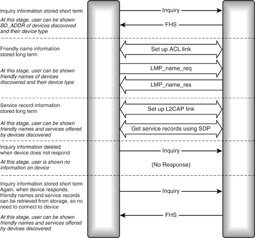
The inquiry procedure allows the user to be told the Bluetooth Device Address (BD_ADDR) and device class of any devices which answer the inquiry. The first time a device is discovered, it must be connected to retrieve its friendly name. This is likely to be more useful to the user. Then an L2CAP link is established to retrieve service discovery information on services and protocols supported by the device. Whether this stage is done and exactly what service discovery information is retrieved will depend on the device. A device which only supports the Bluetooth audio gateway profile would only be interested in retrieving more information from devices in the audio device class, and when it connected to them, it would only retrieve the headset service record. A PC which supported many Bluetooth profiles might retrieve information from a wide variety of devices and would be interested in more services.
The friendly name and service discovery information can be stored. Periodic inquiries are used to check that devices are still in the neighbourhood and available for connection. When a device disappears from view, its information is no longer presented to the user, but the friendly name and service discovery information are still stored. Then when the device again answers an inquiry, there is no need to form a connection; the information on the device can be retrieved from storage.
Service discovery provides a status record which changes whenever a service discovery database changes, so devices may choose to periodically connect to devices in their area to check that their stored service discovery information is up to date by examining the status of their neighbours service discovery records.
Retrieving and storing information on a variety of devices like this uses power for the links and memory for storage. Some devices will follow this way of operating, but for others, limited memory resources and the need to conserve battery power will make it impractical. Such devices may only retrieve information when specifically requested by the user. Applications designers will have to trade off convenience for the user against resource usage in the device.
This section has considered a point to point device which inquires to discover other devices in the neighbourhood. Of course, devices may also inquiry scan and reply to inquiries, passing on information about themselves. This allows other devices to initiate connections. When an incoming connection is received, a device might wish to consult its cached information to see if it can retrieve information on the connecting device, and if it has no information, it may wish to initiate procedures to build up information such as the friendly name for the connecting device.
18.1.3 Point to Multipoint Devices
Point to multipoint devices can establish links to several devices at once. Once multiple links are in place, the device must handle QOS balancing between the links. That is to say, it must decide how much bandwidth to allocate to each link.
Higher layer protocols and services will pass down bandwidth requirements, and initially these will be used to allocate bandwidth to the various links. If the radio environment deteriorates, it is possible that the link will have to shift from using high rate data packets which carry little error protection (DH packets), to lower rate data packets which can correct errors (DM packets). This will reduce the overall bandwidth available. Depending upon the source of interference, a change in the local radio propagation environment may affect some links but not others.
When link quality deteriorates to below the QOS which has been granted to higher layers, the lower layers send QOS violation events to the higher layers. If there is a deterioration in link quality which affects all links, there is a choice: the bandwidth split between all links could be kept the same, in which case all higher layer protocols and services are sent QOS violations, or the device could choose to shut down low priority connections preserving the bandwidth for higher priority connections.
Bluetooth does not define a method for prioritising applications for the purposes of allocating bandwidth, so a suitable scheme would have to be designed to suit the needs of an application running on a particular device by its systems designers. One can envision a system where a connection in use by a WAP micro-browser might be given high priority because delays would be very visible to the user, whereas a connection being used to transfer email might be given lower priority because delays would be less visible.
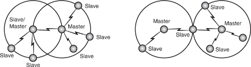
18.1.4 Scatternets
A group of linked piconets joined by common members is called a scatternet. The members linking the piconets can be Slaves on both piconets, or a Master of one piconet and a Slave on another. It is not possible to have a device which is a Master on two different piconets because a piconet is a group of devices hopping on a sequence defined by the clock and Bluetooth device address of the Master. All devices with the same Master must be on the same piconet, and conversely, two different Masters are needed to make two piconets.
Figure 18–3 shows two different scatternets. On the left is a scatternet where one device is a Slave in one piconet and a Master in another. On the right is a scatternet where one device is a Slave in two piconets.
Figure 18–3 Scatternets.
The devices that link the scatternet must maintain two different hop sequences, and must communicate in two different time domains. The devices that are present on more than one piconet do this by time sharing. They spend a few slots on one piconet synchronised to its hopping sequence and timing, then change the hop sequence and timing to match the other piconet and spend a few slots communicating in that time domain.
When switching between timings, there will be some slots which cannot be used. In Figure 18–4, the area above the top line shows the packets transmitted and received by the Master of Piconet 1. The middle line shows packets transmitted and received by one of its Slaves, which is also the Master of a second piconet, 2, and the bottom line shows packets transmitted and received by a Slave on Piconet 2. Starting at the left Master 1 transmits and receives to its Slave. The Slave then moves timing onto its own piconet. It wants to transmit to its own Slave, but because of the difference in timing between the two piconets, it doesn’t have time to retune its radio and transmit, so it has to leave a slot pair and wait to transmit and receive. Then it can retune again and return to Piconet 1. This time it has more time to retune, so it can use the next free slot pair.
Figure 18–4 Scatternet timing.
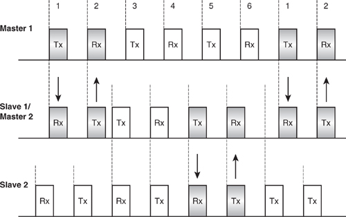
The time spent moving between the timings has meant that during six slot periods, the device which is present on two piconets has only been able to send and receive two packets. Effectively its bandwidth has been reduced by a third. If a higher layer application were using this device to move data between two piconets, it would effectively use six slots to transfer packets between Master 1 and Slave 2, when it would only have needed two slots had they been on the same piconet.
In this example, Slave 1/Master 2 switches timing after each slot pair. This is particularly inefficient (and as we shall see below, practical limitations of negotiating sniff parameters could make such rapid switching awkward). The device could transfer data faster by spending more time on each piconet, but it will still lose bandwidth each time it does a timing switch. The time spent on one piconet will be limited by the need to stop link timers expiring while it is absent from the other piconet.
Because of problems with changing between different slot timings, a device which is present on two piconets will never be able to use the full bandwidth it would have if it were only on one piconet. Each time it changes timing, some slots will be lost, so its available bandwidth will always be lower than a device which is only present on one piconet.
This raises the obvious question: Why not unite the timings, so that the whole scatternet is synchronized? At first thought, this seems like an attractive proposition, but consider the case shown in Figure 18–5.
Figure 18–5 Linking scatternets.

This figure shows the scatternet on the left being united with the scatternet on the right by the link shown in white. In order for the whole scatternet to be united on one timing sequence, timing information would have to be passed around every device on the new scatternet. Bluetooth does not provide a means to pass this information between devices. Also, as scatternets formed and broke, if timing was shared between members of a scatternet, then every device in an area would tend to end up on the same timing sequence. This would increase the chance of packets in different piconets colliding, as all devices would be transmitting together, and all devices would be retuning their radios to hop frequencies together. By increasing the chance of packets colliding, this mass synchronisation effect would lower the overall bandwidth available to piconets in an area.
Another issue associated with managing devices in scatternets is the time a device is missing from one piconet while participating on another piconet. There are two aspects to this:
- A Master that is missing from a piconet may miss polling Slaves and must ensure that it does not miss beacon slots and sniff slots of its Slaves, or links may time out.
- A Slave that is missing from a piconet could appear to its Master to have gone out of range, or to be in a poor quality link.
Dealing with a Master missing from its piconet is fairly simple. When the Master negotiates link parameters such as sniff slots, beacon slots, and poll intervals, it must ensure that it will be present on the piconet at the points where it needs to transmit to sniffing Slaves and parked Slaves, and it must ensure that it will have enough spare capacity on the piconet to poll all of its Slaves before their link timeouts elapse. As a Master controls a piconet, this is just a matter of doing the arithmetic to ensure that it is not over-committed. The actual timing of sniff slots and beacon parameters is negotiated by link manager, the higher layers merely request intervals. The link manager may have to renegotiate sniff and beacon slots when a Master establishes a link to a second piconet. If the link manager is not intelligent enough to automatically renegotiate the sniff and beacon slot timings, renegotiation could be forced by higher layers requesting that Slaves be removed from Park and Sniff modes, then put in Hold mode while the scatternet link is established. Once the scatternet link is established and the Master knows the time it will spend on the second piconet, its Slaves could be put into Park and Sniff modes again.
For the Slave side, handling presence on two piconets requires the cooperation of the Master. The Master must agree not to communicate with the Slave while it is absent. If this is not done, the Master will try to contact the Slave and will get no response. The Master may keep retransmitting, wasting its power while it tries to contact a Slave who is absent because it is communicating on a different piconet. When the Master fails to contact the Slave, it may conclude that the link is poor quality. This could trigger a switch from high-rate (DH) packets to medium-rate (DM) packets. (The medium-rate packets have less data capacity but more error protection, so they are used on poor-quality links.) If the link is actually good quality but the Slave is just not listening, then the channel quality-driven switch to medium-rate packets will unnecessarily reduce throughput on the link.
To save the Master’s power and to avoid misleading the Master on link quality, the Slave could negotiate periods where it is out of communication. The way to arrange this is for the Slave to negotiate Sniff mode with its Master. During the sniff slots, it will be present on the piconet and able to communicate. In between the sniff slots, it can leave and visit the other piconet. The timing of the first sniff slot is determined by the link manager, so the link manager must know when the device will be present on each piconet. Figure 18–6 shows how sniff slots can be used to allow a device to participate in two piconets.
Figure 18–6 Managing scatternet timings with Sniff mode.

The upper line shows the sniff slots on one piconet, and the lower line shows the sniff slots on the second piconet. If the LM of the device which is present on two piconets can negotiate these sniff slots, then it can move between piconets without a Master deciding its link to the device has deteriorated or failed.
Because a device may not get a perfect transmission in its first sniff slot, it would be wise to negotiate several slots for the sniff attempt. The HCI sets the minimum length of sniff timeout to a single slot, so if Sniff mode is used to manage a device’s movement between piconets, there will always be at least one slot in the sniff timeout. This limits the speed with which a sniffing device can switch piconets. However, as explained above, rapidly switching piconets can be a bad idea, as bandwidth is lost on every switch between time domains.
In addition to balancing sniff slots, beacon slots, and poll intervals, a device which is present on two piconets must also handle QOS balancing between the links on the two piconets. Here the issues are similar to balancing QOS between multiple links on one piconet, except that if more bandwidth is to be given to one piconet, then sniff slots have to be renegotiated.
Although the sniff mechanism provides for the possibility of gracefully negotiating absence from a piconet, the Bluetooth specification does not explicitly provide for it to be used in this way, so it is possible that the link managers in many implementations may not be intelligent enough to take into account piconet timing switches when negotiating sniff slots for devices which are present on more than one piconet.
Also, while it is theoretically possible to manage scatternets with Sniff mode in this way, one must question whether it is the best use of available bandwidth. Data rates in the sniffing Slave would be reduced to the point where it might make more sense to manage communications with multiple piconets by alternately using Hold mode on each piconet and communicating in longer bursts.
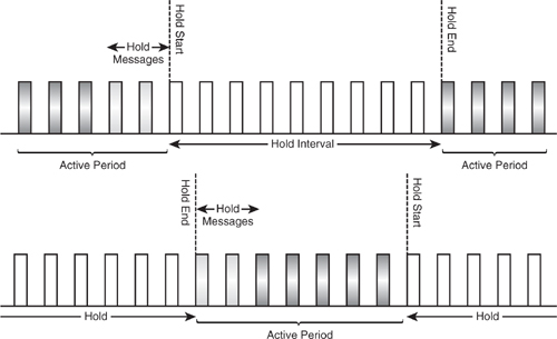
Figure 18–7 shows how Hold mode might be used to manage presence on two scatternets. The device communicates in bursts on one piconet while it is in Hold mode on the other piconet. Bandwidth is only lost due to exchange of LMP messages to negotiate the hold, and for some guard slots when moving between the two piconets timings. The example shown here has just two slots lost for hold messaging; obviously a Master which had to put multiple Slaves on hold would require more slots. One possible drawback of using Hold mode to manage scatternets is that Slave devices can not guarantee to negotiate suitable hold intervals with their Master.
Figure 18–7 Managing scatternet timings with Hold mode.
It is possible that because of the low bandwidth of scatternet links and the fact that a scatternet device is not present on any piconet continuously, they may prove of little use to most devices. None of the profiles released with version 1.0b and 1.1 required the long-term use of scatternets (although the LAN access profile moves through a phase where a device maintains two sets of timings, this is only done as part of connection setup, and the scatternet configuration is not used for user data transfer).
In summary, there are two main management issues involved in scatternet operation.
- Bandwidth is reduced by the time taken to switch between piconets (though this effect is reduced if the switch is done infrequently).
- Devices are absent from one piconet when present on the other, and this absence should be managed, if maximum efficiency is required.
Managing piconets involves calculation and negotiation of parameters for QOS, and may also involve beacon slots, sniff slots, or hold times.
18.2 Device Manager Architecture
Section 18.1 looked at some of the issues involved in managing Bluetooth links for devices with different capabilities. The diversity of management needs is an argument for developing a separate device management entity for Bluetooth protocol stacks. If management is handled in a separate functional block, then only that block needs to be tailored to fit different devices; the remainder of the functional blocks can remain identical.
L2CA is the other main candidate for a functional block to handle device management. The L2CAP data transfer features are identical in all profiles and device types, as are its segmentation and reassembly features, and its interfaces to HCI; even the interfaces to higher layers of the protocol stack do not need to differ between devices. If device management is extracted into a separate functional block, then L2CA becomes a device-independent block which can be reused in many implementations. Of course, this is not a consideration for anybody who is only implementing a single device. However, given the effort involved in implementing a Bluetooth protocol stack, it is likely that the implementation will be reused in more than one device.
The device manager can handle configuration and control of the Bluetooth device, including the facilities required by the Generic Access Profile (GAP). Examples of features which could be handled by a device manager are:
- Setup, teardown, and configuration of the baseband links.
- QOS tradeoffs between links and setting of QOS parameters.
- Management of higher layer links.
- Discovering devices in the neighbourhood and caching information on them.
Figure 18–8 shows how a device manager might be placed in a Bluetooth protocol stack.
Figure 18–8 Bluetooth protocol stack with device manager.
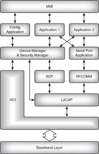
Because the device manager must control the baseband, it has an interface to HCI. It also interfaces to RFCOMM and L2CA to allow it to track the setup of links at various levels of the protocol stack. If the device manager is aware when higher layer links are set up and torn down, it can tear down the baseband links when there are no longer any higher layer links using them.
The device manager acts as a translator between applications and the functional blocks of the Bluetooth protocol stack. When applications request links, they request them from the device manager. When they wish to discover devices in the neighbour-hood, those requests also go through the device manager. Configuration control and information on the neighbourhood passes through the device manager; transfer of raw data does not involve the device manager.
18.2.1 Configuration Application
Some part of the system must handle the initial startup of the system. This is shown in Figure 18–8 as a separate configuration application. On power up, this causes the Bluetooth baseband to be reset. It also sets the device properties: page, inquiry, and scan intervals, user friendly name, and so forth.
The configuration application could be built into the device manager, or it could be part of an application supporting a profile. In a complex device supporting many profiles, it is possible that the device will frequently be reconfigured, and depending upon the mode in which it is being used, it may want to select from several different sets of startup settings. For instance, a laptop could power up a Bluetooth module with different settings depending upon whether it is currently running from mains power or from battery power. If the laptop switches between battery powered and mains powered, the configuration application could be notified and could reconfigure the Bluetooth device to suit the new mode of operation. In such complex devices, it makes sense to split off the management function into a separate functional block to ease software design and maintenance.
In devices such as headsets, there will be far fewer configuration decisions to make, and the configuration application could well be combined with another block in the system, either the headset application or the device manager.
18.2.2 Registering Applications
If applications are to request the facilities of the Bluetooth device through the device manager, then there must be a clearly defined interface between the applications and the device manager.
Applications could register with the device manager. As they register, they could tell the device manager which baseband events are of interest to them, and provide callback functions to be used when baseband events of interest to the application occur.
The level of discrimination in events provided by the device manager is a decision for the implementer. At one extreme, one could imagine a complex device manager offering an application interested in audio devices the ability to be notified whenever an inquiry discovers a new audio device. At the other extreme, a simple device manager might just pass up information on all devices discovered regardless of whether they have been seen before, and regardless of their device type.
Figure 18–9 shows an example message sequence chart for applications registering with a device manager. If there is a separate configuration application, it must register before the other applications can use the device manager’s facilities.
Figure 18–9 Device configuration.
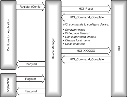
Once applications have registered with the device manager, they receive a ready indication to confirm that the baseband is configured and ready for use. Then they can ask the device manager for connections. The device manager will set up and tear down links as needed. Potentially, a device manager could handle several link types:
- ACL links for use by L2CAP and SCO links.
- L2CAP links for use by SDP and RFCOMM.
- SDP and RFCOMM links for use by applications.
Several applications may share a link, so the device manager maintains a database of applications which are using links and what QOS requirements each application has placed on the link. When applications stop using the link, they signal to the device manager to free the link, and the device manager deletes that application from its database for the link. When the last application using a link frees the link, the device manager can free the link.
Some links may be set up and torn down frequently under this system, so system designers may wish to implement a timeout before the link is shut down.
An example sequence for a system incorporating a device manager could be:
- The configuration application registers, and the device manager configures the baseband.
- A profile application registers.
- The profile application requests SDP information.
- The device manager performs an inquiry via HCI.
- The inquiry result returns information on a remote device.
- The device manager establishes an ACL link to the remote device via HCI.
- The device manager establishes an L2CAP link to the remote device.
- The device manager gets SDP information via SDP (which uses the L2CAP link).
- The device manager passes SDP information to the requesting application.
- If there are no more SDP requests after a timeout, the device manager shuts down links.
This example illustrates how the complexity of Bluetooth management can be abstracted into a device manager. Obviously, if there are many applications in a system it is easier for them to implement a simple interface to the device manager than a complex interface to L2CAP, HCI, and SDP.
18.3 Security Management
Section 18.2 covered how links can be set up and configured, but it is worth considering security configuration separately from general link configuration.
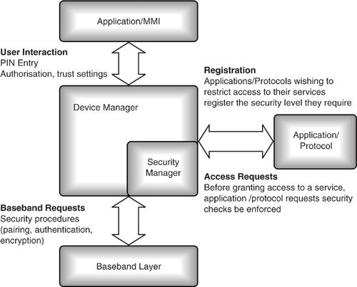
When one application using a link requests security, all traffic on that ACL link is encrypted. A central security manager can turn on encryption when the first application requests it; the other applications will be unaware that this has happened. The security manager could turn off encryption when no application is left using the link which has requested security. To be able to do this, the security manager maintains a database of security requirements.
In the same way that applications register with the device manager, applications wishing to use security services register with the security manager. Each service can register its security level, which is stored in the security database, so there is no need to repeatedly query the application on security. Legacy applications may not understand Bluetooth security requirements, in which case, their requirements could be preregistered in the database. Security services would then be implemented on their behalf by the security manager, without the application ever needing to understand or even be aware of Bluetooth security.
Device-level security settings such as security mode and pairing mode can also be stored in the security database.
The service and device settings for a security profile are modified via user interaction. Although in normal operation the user would be unaware of security procedures; a user could choose to be involved in some security procedures; for instance:
- Access requests—When remote devices request access to local services.
- Security checks such as authentication and pairing are applied as defined by the profile.
- Security checks can be initiated by user interaction.
Most users would not wish to be directly involved in security procedures, so the security manager could also implement bonding. As explained in Chapter 15, bonding allows a user to set up paired relationships before access to facilities is required. Then later on, services can be accessed automatically using the paired relationship, without the user having to get involved and re-entering PINs.
As Figure 18–10 shows, the security manager and device manager have similar interfaces to applications. They also have similar database requirements. They could be implemented as one combined entity.
18.4 Integrating Applications
Applications implement the functionality of the Bluetooth profiles. A Bluetooth application could be a complete solution designed specifically for use in a Bluetooth device. This is likely to be the case for a headset. Alternatively, it could be an existing legacy system which has to be integrated with Bluetooth. This is likely to be the case for dial up networking (modems), where there is a great deal of investment in providing the required functionality from scratch, and far less effort required to integrate an existing system.
The rule when integrating applications with the Bluetooth protocol stack should be to keep the interface to applications as clean and simple as possible. As discussed above, a device manager can be used to simplify the interface to the core Bluetooth control, and a security manager can be used to simplify access control. A configuration application can also be used to simplify startup procedures.
Not only do simple interfaces ease the integration of applications, but they can also help with the process of Bluetooth qualification. Parts of a complete Bluetooth system can be prequalified. If these parts are unchanged in the final system, they do not have to be put through the full qualification process again. Only elements of the system which have changed have to be qualified. For manufacturers with several products to put through qualification, or for those who are buying in prequalified designs, a simple, clean application interface can make the process of deciding which parts to requalify simpler.
Continuing on this theme, it is also worth considering a separate MMI (Man Machine Interface). Because the Bluetooth standard defines the basic functionality of a profile to ensure interoperability, there is limited scope for differentiation in features. One key area for product differentiation is in the user interface. A manufacturer could choose to use a standard Bluetooth solution, but customize the MMI. This allows a range of differentiated products to share the same core.
A reusable core with a variable MMI allows the user interface to be updated without impacting the core (for instance, a new display type might be installed in an upgraded product, or a keypad might be replaced with voice recognition). This minimises development risk and time to market. It also minimises requalification required.
There are several ways to separate the MMI from a core protocol stack:
- Use generic functions for user output and to communicate messages and alerts. The MMI decides whether these are displayed by LEDs, LCD display, audio output, etc.
- Use generic functions for user input to control the stack. These could be tied to switches, buttons, keypad, voice control, etc.
- Use a registration and callback interface. This allows different MMI systems to connect with the same core.
- Have software systems which interface via macros, so that any customizing can be confined to a thin macro layer.
Generally, when integrating applications, the goal should be to keep interfaces as simple as possible, and wherever possible to hide the complexity of Bluetooth within the core protocol stack, so that applications designers can concentrate on providing application functionality rather than having to deal with Bluetooth system management.
18.5 Accounting Management
Accounting management covers the billing of services. Because Bluetooth devices are cheap and they use the ISM band, which is freely available, there are unlikely to ever be any charges for using a Bluetooth link. This is in contrast to mobile telephones, for instance, where the link is usually charged for.
Just because the ISM band links are free does not mean that there are no billing issues at all in Bluetooth systems. As an example, consider a LAN access point in a public place which users may connect with. The LAN access point is providing a useful service which could be charged to the user, but to charge for a service, its use must be restricted to those who pay, and how it is used must be tracked somehow.
PINs can be used to restrict access to services over Bluetooth links. It would be possible to give each user a separate PIN. Users could then pay per hour, and once their time was used up, the LAN access point could be reconfigured via network to not accept connection with the expired PIN.
Paying per megabyte would be more difficult as management and overhead traffic is transferred on a Bluetooth link. Users do not want to pay for system administration traffic. Anyway, Bluetooth does not provide any standardised way to monitor quantities of data transferred on a link. So to charge by traffic usage, this would have to happen at a higher level in the protocol stack.
PIN-restricted access time is certainly the simplest system for controlling access to Bluetooth links. Other systems are technically feasible, but are not provided for in the standard and might require a specially modified L2CAP layer.
18.6 Capacity
The Bluetooth specification provides QOS features for managing link capacity. A Blue-tooth device manager could participate in the process of managing link capacity. This would be done by choosing packet types on links, juggling QOS requirements between links, refusing connections when QOS can’t be met, handling QOS violations, and setting the policy on when to abandon a link with poor quality service characteristics.
As more Bluetooth devices are switched on in an area, they will eventually start to interfere with one another, and link quality will inevitably deteriorate. Because Bluetooth implements a random frequency hopping sequence, collisions will be random, and deterioration of the radio propagation environment due to interference will be gradual. Blue-tooth is a robust protocol which is tolerant of errors, thanks to many levels of error correction and the ability to retransmit. So as link quality deteriorates, this will not be seen as errors on the link; rather, it will appear as reduced throughput.
Applications such as file transfers may request high bandwidth, but they can tolerate slow and bursty data rates. Such applications can usefully be kept running even in very poor link conditions.
Isochronous applications, that is to say those which are transmitting time bounded information, cannot tolerate variable delays. Variable delays will appear in crowded environments where there are frequent random collisions between Bluetooth piconets, causing frequent retransmissions. A device management function could shut down isochronous applications when link quality deteriorates in this way.
18.7 User Interface Design
The processes involved in managing Bluetooth devices can be quite complex. If Blue-tooth is to succeed, it is vital that this complexity is hidden from the end user. If two Blue-tooth products are brought into close proximity, the user should be able to establish a connection between them with as little thought as joining them with wires. It is useful to consider an example of how a pair of Bluetooth-enabled devices might connect and how this might appear to the user.
Consider a cellular mobile phone handset which is switched on in the same area as a Bluetooth headset and a Bluetooth enabled printer. The phone could automatically send an inquiry. Devices within reach, including the headset and a printer, answer with FHS packets. The phone knows from the device classes carried in the FHS packet what types of devices have answered. It also knows that it cannot use the services of a printer, so it ignores this device.
The headset looks more interesting, so the phone connects to it and requests its user friendly name, then establishes an L2CAP connection and sends a service discovery request to see if it supports the headset profile. The phone then displays the headset as an icon with its user friendly name beneath it. The user can select the icon to establish a connection. All the user sees is a device pop up on the screen; all the complexity of inquiring, connecting, and retrieving information is hidden.
One drawback to this procedure is that establishing connections to every device in an area could take some time, and the user may get impatient with the wait. So alternatively, the user interface could display interesting devices with an icon representing their device class when they are first discovered. Then, as more information becomes available, it could be added to the display. Some sort of progress bar could be used to indicate how far the device had progressed through the process of retrieving information.
Yet another possibility is to avoid having automatic device discovery and put the user in control of the whole process. For devices with very stringent battery requirements, it could be useful for the user to be able to completely power down the Bluetooth module in a product when it is not needed. In this case, the user would have to initiate the discovery process. This could be done in a variety of ways—for instance, by selecting from a menu, pressing a button, or clicking on an icon. Only when the user did this would the Bluetooth module begin to discover other devices in its neighbourhood. In this way, battery life would be extended.
Designers of user interfaces must also consider how much of the underlying nature of Bluetooth is exposed to the user. As discussed earlier in Chapter 2 the placing and orientation of an antenna will affect signal strength, and this in turn will affect the quality of the Bluetooth link. It is common for cellular phones to display signal strength indicators on the user interface. These allow users to move to areas of better reception. Similarly, Bluetooth user interfaces could display signal strength obtained from the HCI_Read_RSSI command. This would allow users to site devices in the best positions for a reliable link. However, such displays move Bluetooth away from direct cable replacement, so some device designers may choose not to expose the user to this sort of information.
For battery-operated devices, battery charge indicators will also be useful, although for many devices, such as laptops and cellular phones, these will already be incorporated into the user interface.
Because presenting extra information to the user requires better display capabilities and the exchange of more informational messages, system and application designers will have to trade off the simplest interface for the user against the requirements to produce cheap devices with long battery life.
18.8 Summary
Bluetooth system designers have many issues to deal with in managing Bluetooth links. Because they are radio links, quality is variable, and devices move in an out of radio coverage, giving a highly dynamic networking environment quite unlike more traditional networks.
This poses management challenges for the Bluetooth system designer. There are no standard solutions to these management issues. Because they do not affect interoperability, they are not covered by the Bluetooth specification. There are also no standard answers because the architecture of Bluetooth systems will vary. The architecture will depend upon the complexity of the device. What is appropriate for a complex device such as a PC implementing several profiles will not be appropriate for a simple device such as a Bluetooth headset.
One possibility is abstracting link management, device management, security, and configuration into separate device manager and security manager functional blocks. This allows reuse of standard elements of the core protocol stack, while preserving flexibility in system management.
However management of a Bluetooth device is accomplished, it is vital that it be unobtrusive. A user should find linking devices with Bluetooth wireless technology as easy as joining devices with a cable. Application designers should bear in mind that if the user is exposed to complex configuration and management, then Bluetooth will have failed in its aim to be easy to use.