
Chapter 6. Lighting Models
In the real world, you can’t see objects without light; an object either reflects a light source or emits light itself. In computer rendering, you simulate the interaction of light to add nuance and interest to your 3D objects. But the interplay of light is an extremely complex process that you can’t replicate at interactive frame rates (at least, not yet). Therefore, you use approximations, or models, of how light interacts with 3D objects to add more detail to your scenes. This chapter introduces some of these basic lighting models.
Ambient Lighting
Ambient light is the seemingly ubiquitous “glow” that exists in a lit environment. Look under your desk, for example, and you’ll still be able to see into the farthest recesses and make out detail, even though no light source is directly illuminating that space. This glow exists because of the countless interactions of light between surfaces. As a ray of light reaches a surface, it is either reflected or absorbed, in total or in part, and that process continues innumerable times. So some light does reach under your desk, even if just a little.
You can achieve a simplified approximation of ambient light by modulating the color of a pixel by some constant value. You could consider this a brightness or intensity filter in which the color of each pixel is multiplied by a value between 0 and 1. As the ambient intensity value approaches 0, the object gets darker. Additionally, you can include color into your ambient lighting model, simulating a light source that isn’t pure white. This requires a modulation value for each of the red, green, and blue (RGB) channels of a pixel. Listing 6.1 presents the code for an ambient lighting effect.
Listing 6.1 AmbientLighting.fx
/************* Resources *************/
#define FLIP_TEXTURE_Y 1
cbuffer CBufferPerFrame
{
float4 AmbientColor : AMBIENT <
string UIName = "Ambient Light";
string UIWidget = "Color";
> = {1.0f, 1.0f, 1.0f, 1.0f};
}
cbuffer CBufferPerObject
{
float4x4 WorldViewProjection : WORLDVIEWPROJECTION < string
UIWidget="None";
>;
}
Texture2D ColorTexture <
string ResourceName = "default_color.dds";
string UIName = "Color Texture";
string ResourceType = "2D";
>;
SamplerState ColorSampler
{
Filter = MIN_MAG_MIP_LINEAR;
AddressU = WRAP;
AddressV = WRAP;
};
RasterizerState DisableCulling
{
CullMode = NONE;
};
/************* Data Structures *************/
struct VS_INPUT
{
float4 ObjectPosition : POSITION;
float2 TextureCoordinate : TEXCOORD;
};
struct VS_OUTPUT
{
float4 Position : SV_Position;
float2 TextureCoordinate : TEXCOORD;
};
/************* Utility Functions *************/
float2 get_corrected_texture_coordinate(float2 textureCoordinate)
{
#if FLIP_TEXTURE_Y
return float2(textureCoordinate.x, 1.0 - textureCoordinate.y);
#else
return textureCoordinate;
#endif
}
/************* Vertex Shader *************/
VS_OUTPUT vertex_shader(VS_INPUT IN)
{
VS_OUTPUT OUT = (VS_OUTPUT)0;
OUT.Position = mul(IN.ObjectPosition, WorldViewProjection);
OUT.TextureCoordinate = get_corrected_texture_coordinate(IN.
TextureCoordinate);
return OUT;
}
/************* Pixel Shader *************/
float4 pixel_shader(VS_OUTPUT IN) : SV_Target
{
float4 OUT = (float4)0;
OUT = ColorTexture.Sample(ColorSampler, IN.TextureCoordinate);
OUT.rgb *= AmbientColor.rgb * AmbientColor.a; // Color (.rgb) *
Intensity (.a)
return OUT;
}
/************* Techniques *************/
technique10 main10
{
pass p0
{
SetVertexShader(CompileShader(vs_4_0, vertex_shader()));
SetGeometryShader(NULL);
SetPixelShader(CompileShader(ps_4_0, pixel_shader()));
SetRasterizerState(DisableCulling);
}
}
AmbientColor Shader Constant
You likely noticed that much of this code is identical to that of the texture mapping effect of the last chapter. Building off previous effects is a pattern going forward.
The first difference is the AmbientColor shader constant, a float4 representing the color and intensity of your ambient light. The color of the light is stored within the RGB channels, and the intensity is stored within the alpha channel. Also notice that this variable is contained within a new cbuffer, named CBufferPerFrame. Recall from the discussion of constant buffers in Chapter 4, “Hello, Shaders,” that cbuffers are commonly organized according to the intended update frequency of the contained data. In this case, the AmbientColor value will likely be shared across multiple objects and will need updating only with each frame. This is in contrast to the WorldViewProjection object, within CBufferPerObject, which differs for every object using the AmbientLighting effect.
Note also the AMBIENT semantic associated with the AmbientColor constant. As with all shader constants, this semantic is optional, but it’s not a bad idea to mark variables with semantics so that the CPU-side can look up the value by semantic instead of a hard-coded name.
Finally, notice that the AmbientColor constant is initialized with the value {1.0f, 1.0f, 1.0f, 1.0f}. This yields a white, full-intensity ambient light that won’t change the output color of your objects. So if you ignore this variable from the CPU side, it won’t negatively impact your output.
The rest of the code is the same as the texture mapping effect, up to the pixel shader.
Ambient Lighting Pixel Shader
The pixel shader starts by sampling the color texture and then modulates the output. Specifically, the RGB channels of the output color are multiplied by AmbientColor.rgb * AmbientColor.a. Multiplying a vector (the AmbientColor.rgb float3) by a scalar (the AmbientColor.a float) performs the multiplication for each component of the vector. Thus, the color of your ambient light is first adjusted by the light’s intensity; then the output RGB channels are multiplied (component-wise) from the resulting product.
Ambient Lighting Output
Figure 6.1 shows the output of the ambient lighting effect applied to a sphere with the texture of Earth. On the left, the light is pure white at half intensity (an alpha channel value of 0.5). On the right, the light is red (a value of 1.0 for the red channel and 0.0 for the blue and green channels) at full intensity (an alpha channel value of 1.0).
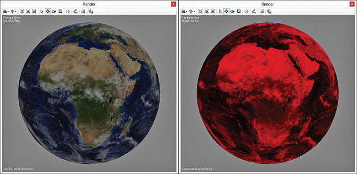
Figure 6.1 AmbientLighting.fx applied to a sphere with the texture of Earth with a pure-white, half-intensity ambient light (left) and a pure-red, full-intensity ambient light (right). (Original texture from Reto Stöckli, NASA Earth Observatory. Additional texturing by Nick Zuccarello, Florida Interactive Entertainment Academy.)
You can modify the values of the ambient light through NVIDIA FX Composer’s Properties panel (see Figure 6.2). Note that the name of the AmbientColor shader constant displays as Ambient Light because of the associated UIName annotation, and that the color picker is presented for editing because of the UIWidget annotation.
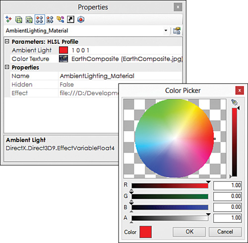
Figure 6.2 NVIDIA FX Composer’s Properties panel showing the Ambient Light constant and color picker dialog.
Note
As a general rule, you won’t perform mathematical operations from within a shader that produce a constant value. For example, the ambient color * ambient intensity product should be multiplied on the CPU side and passed in as the ambient color shader constant. You do so here only because you’re using NVIDIA FX Composer as your CPU-side application and you have limited access to computation before shader execution.
Diffuse Lighting
Different surfaces reflect light in different ways. Mirrors reflect light with an angle of reflection equal to the angle of incidence. That spooky-looking “glow” you see when you shine a light in a cat’s eye reveals its retroreflective properties: It reflects light back to the source along a parallel vector in the opposite direction. Diffuse surfaces reflect light equally in all directions.
Perhaps the simplest and most common model for approximating a diffuse surface is Lambert’s cosine law. Lambert’s cosine law states that the apparent brightness of a surface is directly proportional to the cosine of the angle between the light vector and the surface normal. The light vector describes the direction the light is coming from, and the normal defines the orientation of the surface (which way it’s facing). Figure 6.3 illustrates these terms.
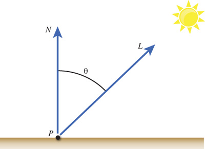
Recall from our discussion of vectors in Chapter 2, “A 3D/Math Primer,” that you can use the dot product to find the cosine of the angle between the light vector and the surface normal (given that the two vectors are of unit length). The surface normal can be computed (through a cross-product of two of the edges of a triangle) or, more commonly, supplied for each vertex when loading a 3D object. This leaves the source of the light vector.
Directional Lights
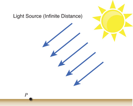
There are three common types of light that are defined in 3D graphics: directional lights, point lights, and spotlights. A directional light represents a light source that is infinitely far away—it has no position relative to your 3D objects. As such, the light rays that reach your objects are parallel to one another—they all travel in the same direction. The sun (while not infinitely distant) is a good example of a directional light. It’s so far away that you cannot discern a difference in the direction of individual rays of light. Figure 6.4 illustrates this concept.
To model a directional light, you simply need a three-dimensional vector describing where the light is coming from. You can also include the concept of color and intensity, just as you did for ambient lighting. Listing 6.2 presents the code for a diffuse lighting effect using a single directional light. Quite a bit is going on here, so I recommend that you transpose the code into NVIDIA FX Composer and then examine the effect step by step. (Alternately, you can download the code from the book’s companion website.)
Listing 6.2 DiffuseLighting.fx
#include "include\Common.fxh"
/************* Resources *************/
cbuffer CBufferPerFrame
{
float4 AmbientColor : AMBIENT <
string UIName = "Ambient Light";
string UIWidget = "Color";
> = {1.0f, 1.0f, 1.0f, 0.0f};
float4 LightColor : COLOR <
string Object = "LightColor0";
string UIName = "Light Color";
string UIWidget = "Color";
> = {1.0f, 1.0f, 1.0f, 1.0f};
float3 LightDirection : DIRECTION <
string Object = "DirectionalLight0";
string UIName = "Light Direction";
string Space = "World";
> = {0.0f, 0.0f, -1.0f};
}
cbuffer CBufferPerObject
{
float4x4 WorldViewProjection : WORLDVIEWPROJECTION < string
UIWidget="None"; >;
float4x4 World : WORLD < string UIWidget="None"; >;
}
Texture2D ColorTexture <
string ResourceName = "default_color.dds";
string UIName = "Color Texture";
string ResourceType = "2D";
>;
SamplerState ColorSampler
{
Filter = MIN_MAG_MIP_LINEAR;
AddressU = WRAP;
AddressV = WRAP;
};
RasterizerState DisableCulling
{
CullMode = NONE;
};
/************* Data Structures *************/
struct VS_INPUT
{
float4 ObjectPosition : POSITION;
float2 TextureCoordinate : TEXCOORD;
float3 Normal : NORMAL;
};
struct VS_OUTPUT
{
float4 Position : SV_Position;
float3 Normal : NORMAL;
float2 TextureCoordinate : TEXCOORD0;
float3 LightDirection : TEXCOORD1;
};
/************* Vertex Shader *************/
VS_OUTPUT vertex_shader(VS_INPUT IN)
{
VS_OUTPUT OUT = (VS_OUTPUT)0;
OUT.Position = mul(IN.ObjectPosition, WorldViewProjection);
OUT.TextureCoordinate = get_corrected_texture_coordinate(IN.
TextureCoordinate);
OUT.Normal = normalize(mul(float4(IN.Normal, 0), World).xyz);
OUT.LightDirection = normalize(-LightDirection);
return OUT;
}
/************* Pixel Shader *************/
float4 pixel_shader(VS_OUTPUT IN) : SV_Target
{
float4 OUT = (float4)0;
float3 normal = normalize(IN.Normal);
float3 lightDirection = normalize(IN.LightDirection);
float n_dot_l = dot(lightDirection, normal);
float4 color = ColorTexture.Sample(ColorSampler,
IN.TextureCoordinate);
float3 ambient = AmbientColor.rgb * AmbientColor.a * color.rgb;
float3 diffuse = (float3)0;
if (n_dot_l > 0)
{
diffuse = LightColor.rgb * LightColor.a * n_dot_l * color.rgb;
}
OUT.rgb = ambient + diffuse;
OUT.a = color.a;
return OUT;
}
/************* Techniques *************/
technique10 main10
{
pass p0
{
SetVertexShader(CompileShader(vs_4_0, vertex_shader()));
SetGeometryShader(NULL);
SetPixelShader(CompileShader(ps_4_0, pixel_shader()));
SetRasterizerState(DisableCulling);
}
}
Diffuse Lighting Effect Preamble
The first line of DiffuseLighting.fx performs a C-style #include of a text file containing some common functionality used by your growing library of effects. Listing 6.3 presents the contents of Common.fxh. Notice the header guards surrounding the file, and note that the FLIP_TEXTURE_Y define and the get_corrected_texture_coordinate() function have been moved to this file.
#ifndef _COMMON_FXH
#define _COMMON_FXH
/************* Constants *************/
#define FLIP_TEXTURE_Y 1
/************* Utility Functions *************/
float2 get_corrected_texture_coordinate(float2 textureCoordinate)
{
#if FLIP_TEXTURE_Y
return float2(textureCoordinate.x, 1.0 - textureCoordinate.y);
#else
return textureCoordinate;
#endif
}
#endif /* _COMMON_FXH */
Next, notice the new CBufferPerFrame members: LightColor and LightDirection. The LightColor shader constant has the same function as AmbientColor: It represents the color and intensity of the directional light. LightDirection stores the direction of the source light in world space. Note the Object annotations associated with these two new shader constants. This annotation denotes that the variable can be bound to a scene object within NVIDIA FX Composer. Specifically, you can place lights in the NVIDIA FX Composer Render panel and associate those lights to shader constants marked with the Object annotation. We discuss this further in a moment.
Now consider the World variable added to CBufferPerObject. This value is related to the new Normal member of the VS_INPUT struct. Surface normals are stored in object space, just like their associated vertices. You use the normal to compute the diffuse color of the pixel by dotting it with the light vector. Because the light is in world space, the normal must also reside in world space and the World matrix is used for this transformation. You can’t use the World-ViewProjection matrix for the transformation because that concatenated matrix would transform the vector to homogeneous space instead of just world space. Note that the World potentially contains a scaling transformation, and the surface normal should be a unit vector; thus, normalizing the vector after transformation is important.
Diffuse Lighting Vertex Shader
Next, inspect the VS_OUTPUT struct and its two new members: Normal and LightDirection. The first passes the transformed surface normal. The second is a little strange, considering the LightDirection shader constant. This member exists because the global LightDirection stores the direction of the light from the source, but you need the direction of the light from the surface. Therefore, you invert the global LightDirection within the vertex shader and assign it to the corresponding output member. Certainly, you could pass the data in from the CPU side, already in the appropriate direction, and skip the invert operation. Indeed, you should do this. However, NVIDIA FX Composer sends the bound light data from the source, so you need to invert the vector to properly preview the effect within the Render panel. Also notice the normalize() intrinsic invoked with the inverted light direction. This guarantees that the light direction is of unit length, but it could be omitted if the guarantee came from the CPU side.
Diffuse Lighting Pixel Shader
Although some similarities to the ambient lighting effect arise, the diffuse lighting pixel shader (reproduced in Listing 6.4) introduces a lot of new code.
Listing 6.4 The Pixel Shader from DiffuseLighting.fx
float4 pixel_shader(VS_OUTPUT IN) : SV_Target
{
float4 OUT = (float4)0;
float3 normal = normalize(IN.Normal);
float3 lightDirection = normalize(IN.LightDirection);
float n_dot_l = dot(lightDirection, normal);
float4 color = ColorTexture.Sample(ColorSampler,
IN.TextureCoordinate);
float3 ambient = AmbientColor.rgb * AmbientColor.a * color.rgb;
float3 diffuse = (float3)0;
if (n_dot_l > 0)
{
diffuse = LightColor.rgb * LightColor.a * n_dot_l * color.rgb;
}
OUT.rgb = ambient + diffuse;
OUT.a = color.a;
return OUT;
}
First, notice the texture sampling and the calculation of the ambient term. This is reformed a bit, but those are the same steps as before; I’ve just separated out the ambient term to clarify the additive process used to produce the final pixel color.
Next, examine the normalization of the incoming Normal and LightDirection members. Remember that data passing through the rasterizer stage is interpolated, and that process can yield non-unit-length vectors. The math errors here are minor, as are the corresponding visual artifacts. So if you’re running up against performance issues, you can easily omit these operations.
Next, you take the dot product of the light direction and the surface normal and use that value to construct the diffuse color term. Notice the if-statement ensuring that n_dot_l is greater than zero. A negative value for the dot product indicates that the light source is behind the surface and, therefore, should not apply. Applicable dot product values are between 0.0 and 1.0. A value of 0.0 indicates that the light vector is parallel to the surface (and, therefore, has no effect), and a value of 1.0 signifies that the light is orthogonal to the surface (and imparts the highest intensity of light). The diffuse term is then created by multiplying the sampled color by the directional light color and intensity and the dot product.
Diffuse Lighting Output
The final pixel color is produced by adding the ambient and diffuse terms. The color texture supplies the alpha channel. Figure 6.5 shows the diffuse lighting effect applied to a sphere with the same Earth texture as in Figure 6.1. Observe how the image gets darker as the surfaces face farther from the light.
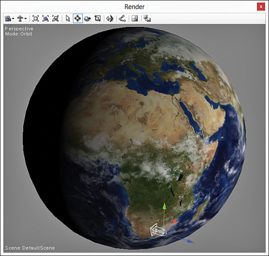
Figure 6.5 DiffuseLighting.fx applied to a sphere with the texture of Earth. (Original texture from Reto Stöckli, NASA Earth Observatory. Additional texturing by Nick Zuccarello, Florida Interactive Entertainment Academy.)
Also notice the directional light at the bottom of this image. NVIDIA FX Composer has options to create ambient, point, spot, and directional lights in the Render panel. To do so, click one of the main toolbar buttons or choose the appropriate selection from the Create menu. For the data of the directional light to be passed into your effect, you must bind your directional light to the LightColor and LightDirection shader constants. This is where the Object annotations come into play. To bind the light, select the sphere in the Render panel and click the Material Instance Properties button in the Properties panel. This is the fifth button in the Properties panel toolbar (see Figure 6.6). Then choose your directional light for the directionallight0 and lightcolor0 bindings. With your light bound to shader constants, any changes you make to the light will be immediately visible. For example, you can rotate your light and observe how the lit areas of the sphere coincide with the direction of the light. But if you translate the light, you’ll see no impact because directional lights have no true position. The position you see for the proxy model of the directional light has no impact on the data passed into the effect.
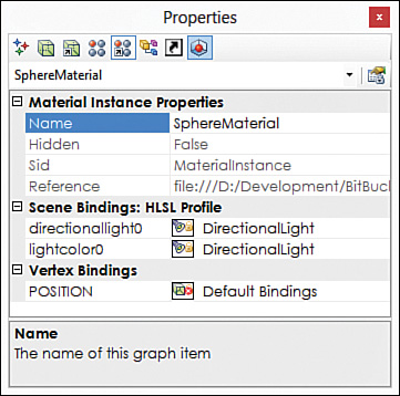
You can also change the color and intensity (stored in the alpha channel) of the directional light. To do so, select the light in the Render panel and open the picker for the Color property in the Properties panel. For the image in Figure 6.5, the directional light is pure white with full intensity, and the ambient light has an intensity of 0 (effectively disabling the ambient light).
Warning
NVIDIA FX Composer supports both automatic and manual binding. When automatic binding is enabled, NVIDIA FX Composer attempts to bind your lights to the appropriate shader constants. Unfortunately, this doesn’t always succeed. Check your material instance properties to determine what has been bound, and manually change the settings, if necessary.
Note, however, that when you recompile your effect, all manual bindings are lost.
Specular Highlights
When you simulate a diffuse surface, you provide a matte, nonglossy appearance. This is appropriate for myriad objects in a scene and forms the base for much of your lighting. But you’ll also want to model shiny surfaces that simulate, for example, polished metal or marble flooring. You can achieve that shiny, glossy look through specular highlights.
Phong
Several approaches approximate specular reflection. The first one we cover is the specular component of the Phong reflection model, named for its inventor, Bui Tuong Phong from the University of Utah.
Unlike diffuse shading, specular highlights depend on where the viewer (the camera) is with respect to the surface. You can observe this yourself; just look at a shiny object and notice how the sheen of it alters as you change your perspective. Phong’s model states that the specular highlight depends on the angle between this view direction and the light’s reflection vector. In equation form:
SpecularPhong = (R • V)s
where, R is the reflection vector, V is the view direction, and s specifies the size of the highlight. A smaller highlight is produced with a larger specular exponent. The reflection vector is computed with the following equation:
R = 2*(N • L)*N-L
where N is the surface normal, and L is the light vector.
Listing 6.5 presents the code for a Phong effect. As before, transpose this code into NVIDIA FX Composer, compile it, and assign the associated material to an object in the Render panel. The following sections review the specifics of the effect.
#include "include\Common.fxh"
/************* Resources *************/
cbuffer CBufferPerFrame
{
float4 AmbientColor : AMBIENT <
string UIName = "Ambient Light";
string UIWidget = "Color";
> = {1.0f, 1.0f, 1.0f, 0.0f};
float4 LightColor : COLOR <
string Object = "LightColor0";
string UIName = "Light Color";
string UIWidget = "Color";
> = {1.0f, 1.0f, 1.0f, 1.0f};
float3 LightDirection : DIRECTION <
string Object = "DirectionalLight0";
string UIName = "Light Direction";
string Space = "World";
> = {0.0f, 0.0f, -1.0f};
float3 CameraPosition : CAMERAPOSITION < string UIWidget="None"; >;
}
cbuffer CBufferPerObject
{
float4x4 WorldViewProjection : WORLDVIEWPROJECTION < string
UIWidget="None"; >;
float4x4 World : WORLD < string UIWidget="None"; >;
float4 SpecularColor : SPECULAR <
string UIName = "Specular Color";
string UIWidget = "Color";
> = {1.0f, 1.0f, 1.0f, 1.0f};
float SpecularPower : SPECULARPOWER <
string UIName = "Specular Power";
string UIWidget = "slider";
float UIMin = 1.0;
float UIMax = 255.0;
float UIStep = 1.0;
> = {25.0f};
}
Texture2D ColorTexture <
string ResourceName = "default_color.dds";
string UIName = "Color Texture";
string ResourceType = "2D";
>;
SamplerState ColorSampler
{
Filter = MIN_MAG_MIP_LINEAR;
AddressU = WRAP;
AddressV = WRAP;
};
RasterizerState DisableCulling
{
CullMode = NONE;
};
/************* Data Structures *************/
struct VS_INPUT
{
float4 ObjectPosition : POSITION;
float2 TextureCoordinate : TEXCOORD;
float3 Normal : NORMAL;
};
struct VS_OUTPUT
{
float4 Position : SV_Position;
float3 Normal : NORMAL;
float2 TextureCoordinate : TEXCOORD0;
float3 LightDirection : TEXCOORD1;
float3 ViewDirection : TEXCOORD2;
};
/************* Vertex Shader *************/
VS_OUTPUT vertex_shader(VS_INPUT IN)
{
VS_OUTPUT OUT = (VS_OUTPUT)0;
OUT.Position = mul(IN.ObjectPosition, WorldViewProjection);
OUT.TextureCoordinate = get_corrected_texture_coordinate(IN.
TextureCoordinate);
OUT.Normal = normalize(mul(float4(IN.Normal, 0), World).xyz);
OUT.LightDirection = normalize(-LightDirection);
float3 worldPosition = mul(IN.ObjectPosition, World).xyz;
OUT.ViewDirection = normalize(CameraPosition - worldPosition);
return OUT;
}
/************* Pixel Shader *************/
float4 pixel_shader(VS_OUTPUT IN) : SV_Target
{
float4 OUT = (float4)0;
float3 normal = normalize(IN.Normal);
float3 lightDirection = normalize(IN.LightDirection);
float3 viewDirection = normalize(IN.ViewDirection);
float n_dot_l = dot(lightDirection, normal);
float4 color = ColorTexture.Sample(ColorSampler,
IN.TextureCoordinate);
float3 ambient = AmbientColor.rgb * AmbientColor.a * color.rgb;
float3 diffuse = (float3)0;
float3 specular = (float3)0;
if (n_dot_l > 0)
{
diffuse = LightColor.rgb * LightColor.a * saturate(n_dot_l) *
color.rgb;
// R = 2 * (N.L) * N - L
float3 reflectionVector = normalize(2 * n_dot_l * normal
- lightDirection);
// specular = R.V^n with gloss map in color texture's alpha
channel
specular = SpecularColor.rgb * SpecularColor.a * min(pow(saturate
(dot(reflectionVector, viewDirection)), SpecularPower), color.w);
}
OUT.rgb = ambient + diffuse + specular;
OUT.a = 1.0f;
return OUT;
}
technique10 main10
{
pass p0
{
SetVertexShader(CompileShader(vs_4_0, vertex_shader()));
SetGeometryShader(NULL);
SetPixelShader(CompileShader(ps_4_0, pixel_shader()));
SetRasterizerState(DisableCulling);
}
}
Phong Preamble
Compared with the diffuse lighting effect, the CBufferPerFrame block has only one addition: CameraPosition. This shader constant stores the location of the camera and determines the view direction. NVIDIA FX Composer automagically binds this constant to the Render panel’s camera when you specify the CAMERAPOSITION semantic.
The CBufferPerObject block has two additions: constants for SpecularColor and SpecularPower. SpecularColor has the same function as the colors for the ambient light and directional light; it designates the color and intensity of the specular highlight. Having this extra “knob” enables you to tweak the specular highlight independently from the directional light. The SpecularPower refers to the exponent value s in the Phong specular equation.
Next, notice the newly added ViewDirection vector in the VS_OUTPUT struct. This passes the calculated view direction along to the rasterizer stage.
Phong Vertex Shader
Within the vertex shader, the view direction is calculated by subtracting the position of the vertex from the camera’s position. However, both positions must reside in the same coordinate space, so first you transform the vertex position (IN.ObjectPosition) by the world matrix.
Phong Pixel Shader
The pixel shader now includes operations for computing the specular term. These steps apply only if the directional light “shines” on the surface, so you encapsulate these statements within the n_dot_l > 0 conditional.
An added twist to computing the specular term requires explanation. Listing 6.6 pulls out just these statements.
Listing 6.6 Computing the Specular Term Within Phong.fx
// specular = R.V^n with gloss map stored in color texture's alpha
channel
specular = SpecularColor.rgb * SpecularColor.a * min(pow(saturate(dot
(reflectionVector, viewDirection)), SpecularPower), color.w);
First, notice the comment stating that the term is calculated through the Phong specular equation. This is performed through the pow() intrinsic, which accepts the dotted reflection and view direction vectors raised to the SpecularPower exponent. The saturate() intrinsic clamps the output of the dot product between 0.0 and 1.0, thereby eliminating negative angles.
The comment also indicates that the calculated value is modulated by a gloss map that is stored in the color texture’s alpha channel. A gloss map, or specular map, either is a stand-alone texture (typically just a single-channel texture format) or is included as part of another incoming texture (as in this example). A specular map limits the computed specular term according to the input of the texture artist. Consider the Earth texture used throughout this chapter. It makes sense that only the water portions of Earth should appear shiny and that the land should have a matte appearance. A specular map allows for this on a per-pixel basis. The min() intrinsic returns the lesser of the computed specular term and the value stored in the alpha channel (the w channel). Thus, a value of 0.0 in the specular map would eliminate any specular even if the computed value would otherwise yield the highest specular intensity (a value of 1.0). Figure 6.7 shows the specular map of Earth used for this section.
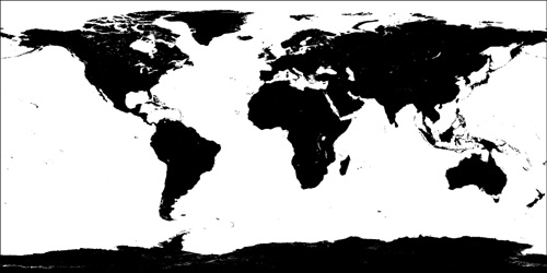
Figure 6.7 Specular map for the Earth texture. (Original texture from Reto Stöckli, NASA Earth Observatory. Additional texturing by Nick Zuccarello, Florida Interactive Entertainment Academy.)
The final pixel color is produced through the combination of the ambient, diffuse, and specular terms. The alpha channel is set to a value of 1.0 (fully opaque) rather than from the color texture because you are using the alpha channel as a specular map instead of opacity. If you require both opacity and a specular map, you need to supply a second texture.
Phong Output
Figure 6.8 shows the result of the Phong effect applied to a sphere with a texture of Earth (without cloud coverage) with and without a specular map. Both images share the same color channels, but notice the difference in the specular highlight between the land and water for the texture with a specular map (left).
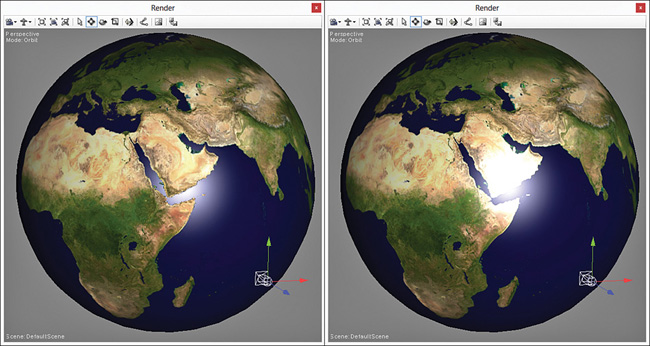
Figure 6.8 Phong.fx applied to a sphere with a texture of Earth with a specular map (left) and without one (right). (Texture from Reto Stöckli, NASA Earth Observatory.)
Blinn-Phong
In 1977, Jim Blinn developed a modification to the Phong specular component that replaces the reflection vector with a half-vector. This vector lies halfway between the view and light vectors and is computed as:
Instead of dotting the Phong reflection vector against the view direction, Blinn-Phong dots the half-vector with the surface normal and raises the result to an exponent. The final equation is:
SpecularBlinn - Phong = (N • H)s
Blinn-Phong Pixel Shader
The preamble and vertex shader for the Blinn-Phong effect is identical to the Phong effect. Therefore, Listing 6.7 presents only the modified pixel shader. You can find the complete effect on the book’s companion website.
Listing 6.7 The Pixel Shader from BlinnPhong.fx
float4 pixel_shader(VS_OUTPUT IN) : SV_Target
{
float4 OUT = (float4)0;
float3 normal = normalize(IN.Normal);
float3 lightDirection = normalize(IN.LightDirection);
float3 viewDirection = normalize(IN.ViewDirection);
float n_dot_l = dot(lightDirection, normal);
float4 color = ColorTexture.Sample(ColorSampler,
IN.TextureCoordinate);
float3 ambient = AmbientColor.rgb * AmbientColor.a * color.rgb;
float3 diffuse = (float3)0;
float3 specular = (float3)0;
if (n_dot_l > 0)
{
diffuse = LightColor.rgb * LightColor.a * saturate(n_dot_l) *
color.rgb;
float3 halfVector = normalize(lightDirection + viewDirection);
//specular = N.H^s w/ gloss map stored in color texture's alpha
channel
specular = SpecularColor.rgb * SpecularColor.a *
min(pow(saturate(dot(normal, halfVector)), SpecularPower), color.w);
}
OUT.rgb = ambient + diffuse + specular;
OUT.a = 1.0f;
return OUT;
}
Notice the removal of the reflection vector and the addition of the half-vector calculation. As before, the specular map limits the calculated specular term. The output of Blinn-Phong is visually identical to that of Phong, although you have to tweak the value of the exponent.
Blinn-Phong with Intrinsics
HLSL provides an intrinsic function, lit(), to compute the Lambertian diffuse and Blinn-Phong specular components for you. A good rule of thumb is to use built-in functions wherever possible because they are likely optimized or implemented in hardware. Thus, you can rewrite your Blinn-Phong pixel shader as in Listing 6.8.
Listing 6.8 Utility Functions and the Pixel Shader from BlinnPhongIntrinsics.fx
float3 get_vector_color_contribution(float4 light, float3 color)
{
// Color (.rgb) * Intensity (.a)
return light.rgb * light.a * color;
}
float3 get_scalar_color_contribution(float4 light, float color)
{
// Color (.rgb) * Intensity (.a)
return light.rgb * light.a * color;
}
float4 pixel_shader(VS_OUTPUT IN) : SV_Target
{
float4 OUT = (float4)0;
float3 normal = normalize(IN.Normal);
float3 lightDirection = normalize(IN.LightDirection);
float3 viewDirection = normalize(IN.ViewDirection);
float n_dot_l = dot(normal, lightDirection);
float3 halfVector = normalize(lightDirection + viewDirection);
float n_dot_h = dot(normal, halfVector);
float4 color = ColorTexture.Sample(ColorSampler,
IN.TextureCoordinate);
float4 lightCoefficients = lit(n_dot_l, n_dot_h, SpecularPower);
float3 ambient = get_vector_color_contribution(AmbientColor, color.
rgb);
float3 diffuse = get_vector_color_contribution(LightColor,
lightCoefficients.y * color.rgb);
float3 specular = get_scalar_color_contribution(SpecularColor,
min(lightCoefficients.z, color.w));
OUT.rgb = ambient + diffuse + specular;
OUT.a = 1.0f;
return OUT;
}
The differences in this pixel shader are significant. Gone are the explicit calculations for the diffuse and specular terms, along with the containing conditional. New is the call to lit(), which accepts the values for n_dot_l and n _dot_h and the specular exponent. The lit() intrinsic performs the same diffuse and specular calculations and returns coefficients for these terms in a float4. The x and w components of the returned vector are always 1. The diffuse coefficient is stored in the y component and specular in z, which you use to produce the corresponding terms.
Also notice the utility functions that perform the multiplications for the light color and intensity. These just make code maintenance easier when, for example, you want to modulate the light color by the intensity on the CPU side instead of calculating a constant within the pixel shader. Store these functions in your Common.fxh file for use across your shader library.
Blinn-Phong vs. Phong
Because the output between Phong and Blinn-Phong is identical, the difference between these models is a question of efficiency. Blinn-Phong could be slower because of the square root (from the normalization of the half-vector). However, because you’ll use the HLSL lit() intrinsic, it’s likely that the built-in implementation of Blinn-Phong yields a minor speed improvement over Phong. I show both models for the sake of instruction and completeness. We use the lit() intrinsic for all future effects that have diffuse and specular terms.
Summary
In this chapter, you learned about a series of introductory lighting models, including ambient lighting, diffuse lighting, and specular highlights. You implemented effects to simulate such lighting and extended your knowledge of HLSL. The next chapter introduces you to even more lighting concepts, including point lights and spotlights, and explores how to use multiple lights in your scenes.
Exercises
1. Experiment with the ambient lighting effect. Modify the ambient light’s color and intensity from within the Properties panel of NVIDIA FX Composer.
2. Explore the output of the diffuse lighting effect. Create a directional light within your scene, and bind it to the color and directional light shader inputs. Rotate the light, modify its color, and observe the results. Additionally, create an Object annotation for the AmbientLight constant, and create and bind an ambient light to this object. Then modify the ambient light in the scene and observe the impact to the rendered output.
3. Vary the specular power in the Phong effect and observe the results. Experiment with different combinations of color and intensity for the ambient, directional, and specular color constants.
4. Implement the complete Blinn-Phong effect, and compare its output to the Phong effect.
5. Implement a Blinn-Phong effect using the HLSL lit() intrinsic, and compare its output to that of the Blinn-Phong effect you implemented in the previous exercise.