
Chapter 3. Controlling the Drawing Display
• Zoom in and out of a drawing
• Refresh the drawing display
• Toggle the ribbon and all palettes off and on
• Make arcs and circles appear smoother
• Increase drawing display regeneration speed by turning off text and solid fill areas
Introduction
The AutoCAD drawing display window is one of the most important features of the AutoCAD user interface. It is here where you do most of your work creating and modifying the objects that make up your drawing. AutoCAD provides a number of tools and settings that allow you to control how and what drawing information is displayed in the drawing display window. The drawing display tools and their settings are explained in detail in this chapter.
Zooming In and Out of a Drawing
The AutoCAD drawing display window is like a camera lens. You control what’s displayed in your drawing by zooming in to get a closer look and by zooming out to see the big picture, similar to a camera.
Unlike most cameras, AutoCAD provides a number of different ways to control the zooming process. The Zoom tools are located on the navigation bar located on the right side of the drawing window, as shown in Figure 3-1.
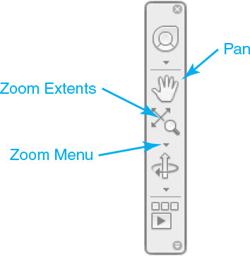
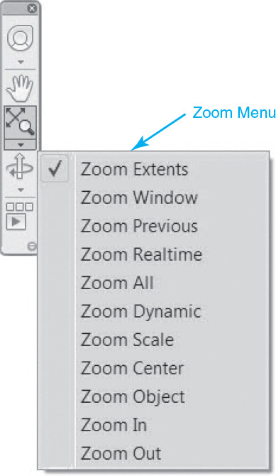
All of the Zoom tools can be displayed by selecting the Zoom Extents tool to display the Zoom flyout menu shown in Figure 3-2. As you can see, there are many different Zoom tools available. Some of the tools are holdovers from early releases of AutoCAD and are beginning to show their age. They still exist in AutoCAD for legacy reasons, for the most part. You will need to refer to the AutoCAD Help for information regarding the legacy Zoom tools. The next section covers most of the Zoom tools that are still relevant today.
Tip
You can turn the navigation bar on and off by selecting the “–” symbol on the in-canvas viewport control on the upper left of the drawing window to display the shortcut menu and selecting/deselecting the Navigation Bar option. Alternatively, you can turn the navigation bar on and off via the NAVBARDISPLAY system variable. Setting NAVBARDISPLAY to 1 turns on the navigation bar and setting NAVBARDISPLAY to 0 turns it off.
Zoom Tools
The following Zoom tools are the easiest to use and provide the most “bang for the buck” when you need to zoom in and out of your drawing quickly. You will likely find yourself using the Zoom tools explained in this section most often out of the many different Zoom tools provided by AutoCAD.
Zoom Extents |
|
Ribbon & Panel: |
None |
Navigation Bar: |
|
Menu: |
View | Zoom | Extents |
Command Line: |
ZOOM |
Command Alias: |
Z |
Zoom Extents
The Zoom Extents tool is very useful because it allows you to view everything in your drawing on your screen quickly. AutoCAD calculates the extents of the outermost objects in your drawing that are not on a frozen layer and then zooms out so that everything is visible. This is especially helpful when you are zoomed in on a small area of your drawing and you draw an object that goes off the screen. Using Zoom Extents allows you to see the complete object.
Sometimes when you use the Zoom Extents tool, it may appear that there is nothing in your drawing—don’t panic. Usually this means that there is some rogue object out in the nether regions of your drawing. If you zoom out just a little, you can usually find the object and determine its identity so that you may move or delete it.
Exercise 3-1 Using the Zoom Extents Tool
![]() Open drawing Willhome located in the student data files.
Open drawing Willhome located in the student data files.
To access student data files, go to www.pearsondesigncentral.com.
![]() Select the Model tab so that model space is active.
Select the Model tab so that model space is active.
![]() Select the Zoom Extents tool on the navigation bar, and zoom to the extents of the drawing.
Select the Zoom Extents tool on the navigation bar, and zoom to the extents of the drawing.
![]() Zoom in on an area of the drawing using your mouse wheel or any of the techniques introduced in Chapter 2.
Zoom in on an area of the drawing using your mouse wheel or any of the techniques introduced in Chapter 2.
![]() Select the Zoom Extents tool again.
Select the Zoom Extents tool again.
![]() All the drawing information is now displayed in the drawing display window.
All the drawing information is now displayed in the drawing display window.
Note
If there are no objects in your drawing or everything is on layers that are currently frozen, the Zoom Extents tool will zoom to the limits of your drawing. See page 135 in Chapter 4 for more information about controlling drawing limits.
Zoom Window
The Zoom Window tool allows you to define a rectangular area, or window, using two mouse pick points so that you can quickly zoom in on a specific area of your drawing. The windowed area is zoomed and centered at a scale that fills your drawing display area.
Zoom Window |
|
Ribbon & Panel: |
None |
Navigation Bar: |
|
Menu: |
View | Zoom | Windows |
Command Line: |
ZOOM |
Command Alias: |
Z |
After selecting the Zoom Window tool, you are prompted to select the two corner points of the window. Select two points in your drawing to define the rectangular area you wish to zoom on as shown in Figure 3-3.
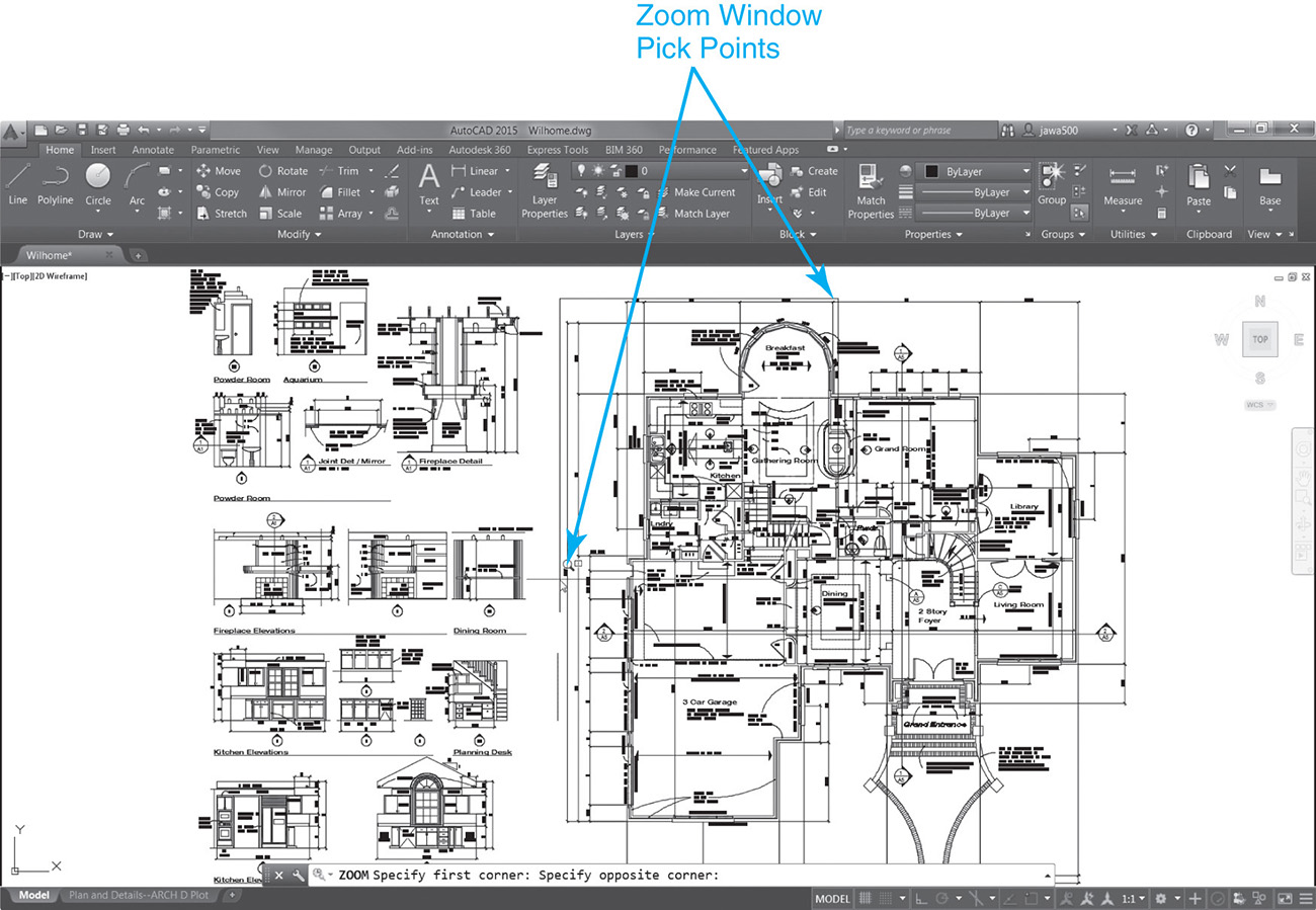
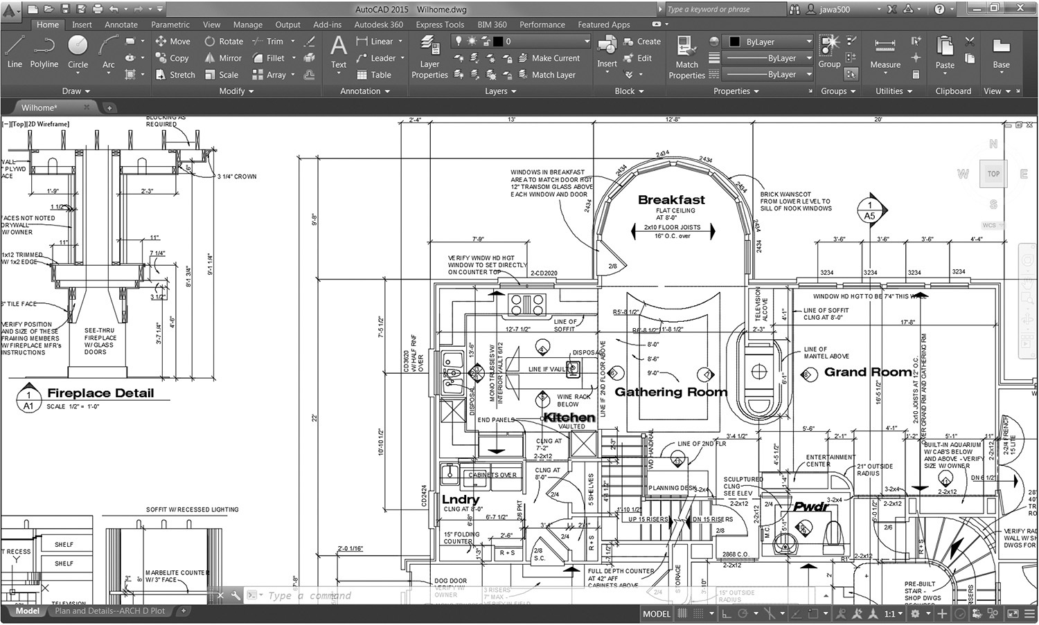
The display is zoomed immediately after selecting the second corner point, as shown in Figure 3-4.
Exercise 3-2 Using the Zoom Window Tool
![]() Continue from Exercise 3-1.
Continue from Exercise 3-1.
![]() Select the Zoom Window tool on the Zoom flyout menu on the navigation bar. AutoCAD prompts you to Specify first corner:.
Select the Zoom Window tool on the Zoom flyout menu on the navigation bar. AutoCAD prompts you to Specify first corner:.
![]() Pick a point in your drawing. AutoCAD places the first point and drags a rectangular rubber-band line from that point and prompts you to Specify opposite corner:.
Pick a point in your drawing. AutoCAD places the first point and drags a rectangular rubber-band line from that point and prompts you to Specify opposite corner:.
![]() Size the rectangle so that the information you want to zoom in on is within the windowed area, and pick another point in your drawing (see Figure 3-3).
Size the rectangle so that the information you want to zoom in on is within the windowed area, and pick another point in your drawing (see Figure 3-3).
![]() After you pick the second point, the windowed area is zoomed to fill the drawing display window (see Figure 3-4).
After you pick the second point, the windowed area is zoomed to fill the drawing display window (see Figure 3-4).
Zoom Previous
The Zoom Previous tool is probably the most popular of the Zoom tools because it allows you to restore the previous drawing display. In fact, you can restore up to 10 previous views, so that you can step back in time. This capability allows you to zoom in on an area of your drawing to get close to your work (see Figure 3-4) and then quickly return to the previous overall view (see Figure 3-3). From there you can zoom in on other areas and then zoom back out again. The combination of the Zoom Window tool and the Zoom Previous tool provides one of the easiest, most efficient ways to navigate around your drawing.
Zoom Previous |
|
Ribbon & Panel: |
None |
Navigation Bar: |
|
Menu: |
View | Zoom | Previous |
Command Line: |
ZOOM |
Command Alias: |
Z |
AutoCAD stores up to 10 previous views. The following message is displayed at the command line if there is no previous view to display:
Command: No previous view saved.
Exercise 3-3 Using the Zoom Previous Tool
![]() Continue from Exercise 3-2.
Continue from Exercise 3-2.
![]() Select the Zoom Extents tool and zoom to the extents of the drawing.
Select the Zoom Extents tool and zoom to the extents of the drawing.
![]() Follow the steps shown in Exercise 3-2, and zoom in on an area of the drawing so that the drawing display looks similar to Figure 3-4.
Follow the steps shown in Exercise 3-2, and zoom in on an area of the drawing so that the drawing display looks similar to Figure 3-4.
![]() Select the Zoom Previous tool on the navigation bar.
Select the Zoom Previous tool on the navigation bar.
![]() The drawing information displayed in the drawing display window returns to the previous view.
The drawing information displayed in the drawing display window returns to the previous view.
![]() Continue selecting the Zoom Previous tool until AutoCAD displays the following prompt at the command line:
Continue selecting the Zoom Previous tool until AutoCAD displays the following prompt at the command line:
No previous view saved.
Note
The Zoom Previous tool does not undo any drawing or editing commands and affects the display only.
Zoom Realtime
Zooming in “realtime” simply means that the zooming process is interactive. As you zoom in, objects grow larger on the screen; as you zoom out, objects grow smaller.
Zoom Realtime |
|
Ribbon & Panel: |
None |
Navigation Bar: |
|
Menu: |
View | Zoom | Realtime |
Command Line: |
ZOOM |
Command Alias: |
Z |
Selecting the Zoom Realtime tool causes the mouse pointer to change to the magnifying glass icon shown in Figure 3-5.
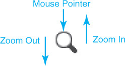
Holding your mouse button down and moving the magnifying glass toward the top of the screen zooms in and increases the display magnification (+). See Figures 3-6A and 3-6B. Holding the button down and moving the magnifying glass toward the bottom of the screen zooms out and decreases the display magnification (−).
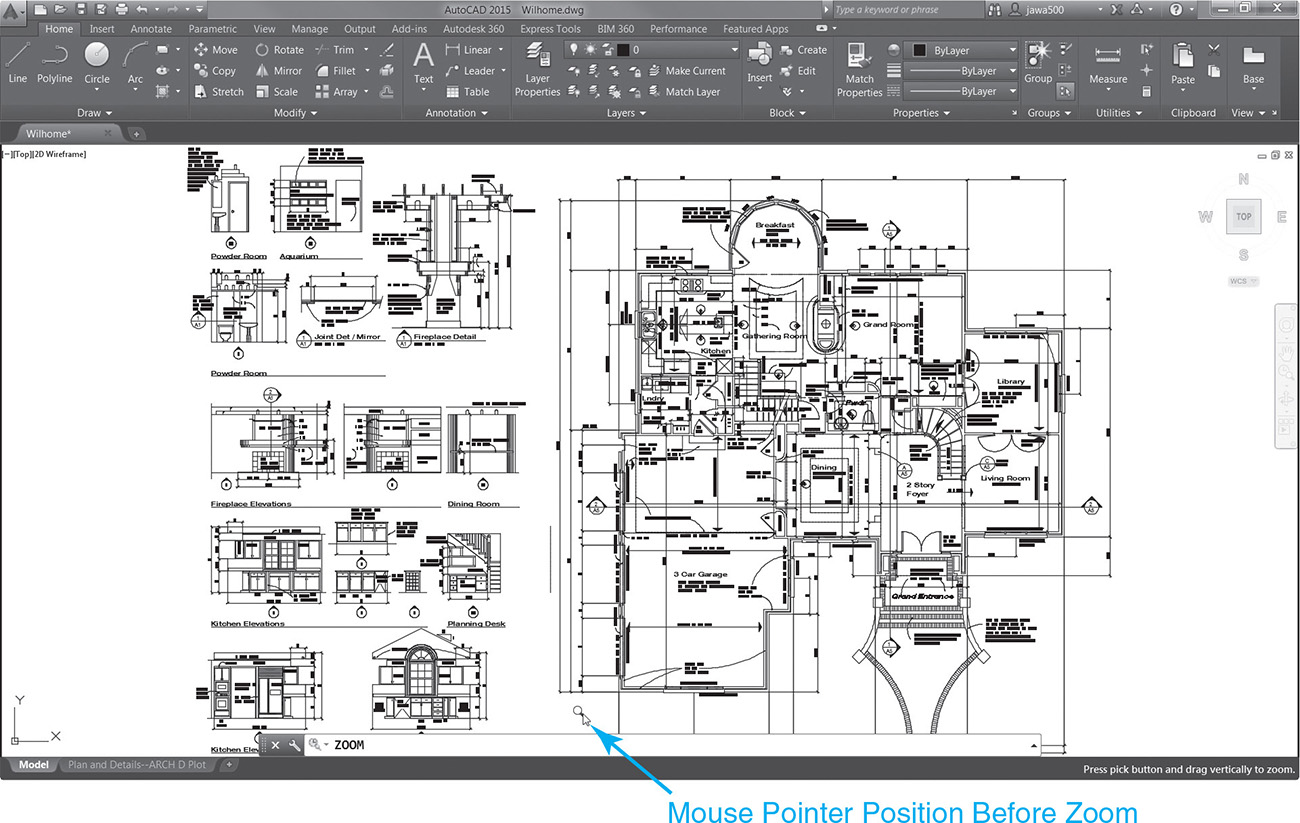
If you run out of mouse pad during the process of moving your mouse up or down the screen, just pick up your mouse, reposition it, and repeat the process. When you are finished zooming and the drawing display appears at the desired magnification factor, press <Enter> or <Esc> to complete the zoom process.
Tip
If you reach a point in zooming in or out when the display will not zoom any farther and appears stuck, don’t worry. This just means that you need to regenerate your display using the REGEN command. The REGEN command is discussed in detail later in the section “Cleaning Up the Drawing Display.”
Exercise 3-4 Using the Zoom Realtime Tool
![]() Continue from Exercise 3-3.
Continue from Exercise 3-3.
![]() Select the Zoom Extents tool on the navigation bar.
Select the Zoom Extents tool on the navigation bar.
![]() Select the Zoom Realtime tool on the navigation bar.
Select the Zoom Realtime tool on the navigation bar.
![]() Notice that your mouse pointer changes to a magnifying glass (see Figure 3-5).
Notice that your mouse pointer changes to a magnifying glass (see Figure 3-5).
![]() Click with your mouse at the bottom of the drawing display window and hold the mouse button down (see Figure 3-6A).
Click with your mouse at the bottom of the drawing display window and hold the mouse button down (see Figure 3-6A).
![]() Drag your mouse to the top of the drawing display window while continuing to hold the mouse button down.
Drag your mouse to the top of the drawing display window while continuing to hold the mouse button down.
![]() Release the mouse button when the mouse pointer reaches the top of the drawing display window (see Figure 3-6B).
Release the mouse button when the mouse pointer reaches the top of the drawing display window (see Figure 3-6B).
![]() Click with your mouse at the top of the drawing display window and hold the mouse button down.
Click with your mouse at the top of the drawing display window and hold the mouse button down.
![]() Drag your mouse to the bottom of the drawing display window while continuing to hold the mouse button down.
Drag your mouse to the bottom of the drawing display window while continuing to hold the mouse button down.
![]() Release the mouse button when the mouse pointer reaches the bottom of the drawing display window.
Release the mouse button when the mouse pointer reaches the bottom of the drawing display window.
![]() Press <Enter> or <Esc> to complete the zoom process.
Press <Enter> or <Esc> to complete the zoom process.
Zoom All
The Zoom All tool zooms either to the extents of the drawing in a fashion similar to the Zoom Extents tool discussed earlier or to the outer reaches of the drawing area that have been established using the Drawing Limits settings (LIMITS command).
Zoom All |
|
Ribbon & Panel: |
None |
Navigation Bar: |
|
Menu: |
View | Zoom | All |
Command Line: |
ZOOM |
Command Alias: |
Z |
For More Details
See page 135 in Chapter 4 for more information about adjusting the drawing area using the LIMITS command.
If the defined drawing area is smaller than the outermost drawing extents, the Zoom All tool zooms to the drawing extents, just like the Zoom Extents tool does. If the drawing area is larger, or past the drawing limits, the Zoom All tool will zoom to the larger area.
Tip
The Zoom All tool can be used in a paper space layout to center the layout, or paper, in the center of your drawing window while leaving a small margin around the edges of the sheet. The Zoom Extents tool can be used too, but the edge of the drawing window abuts the edge of the paper with no margin.
Exercise 3-5 Using the Zoom All Tool
![]() Continue from Exercise 3-4.
Continue from Exercise 3-4.
![]() Select the Zoom Extents tool and zoom to the extents of the drawing.
Select the Zoom Extents tool and zoom to the extents of the drawing.
![]() Select the Zoom All tool. Notice that the drawing zooms out even farther. This is because the drawing area or limits are set to an area much larger than the extents of the drawing.
Select the Zoom All tool. Notice that the drawing zooms out even farther. This is because the drawing area or limits are set to an area much larger than the extents of the drawing.
![]() Select the Zoom Extents tool again to zoom back to the drawing extents.
Select the Zoom Extents tool again to zoom back to the drawing extents.
Using the Mouse Wheel
If you have a wheel mouse, you can use the wheel to zoom in and out. Rolling the wheel toward the computer (away from you) zooms into your drawing. Rolling the wheel away from the computer (toward you) will zoom out of your drawing.
Note
The ZOOMWHEEL system variable controls the default zoom direction when rolling the mouse wheel. Setting ZOOMWHEEL to 0 (default) zooms in when rolling the wheel forward, and setting ZOOMWHEEL to 1 zooms out when rolling the wheel forward.
Each click of the mouse wheel zooms in or out by 10%. You can change this zoom scale factor via the ZOOMFACTOR system variable. The ZOOMFACTOR default value is 60 and can be set to a value of between 3 and 100.
Tip
The mouse wheel also acts as a mouse button. In fact, it can be used to either pan your drawing display or display the Object Snap shortcut menu (see the next section, “Panning Around a Drawing”). It’s also a little-known fact that double-clicking the wheel button will zoom to the extents of your drawing just like the Zoom Extents tool!
Exercise 3-6 Using the Mouse Wheel to Zoom In and Out
![]() Continue from Exercise 3-5.
Continue from Exercise 3-5.
![]() Roll the mouse wheel forward toward your computer screen.
Roll the mouse wheel forward toward your computer screen.
![]() The drawing display zooms in as you roll the mouse wheel forward.
The drawing display zooms in as you roll the mouse wheel forward.
![]() Roll the mouse wheel away from the computer screen or toward yourself.
Roll the mouse wheel away from the computer screen or toward yourself.
![]() The drawing display zooms out as you roll the mouse wheel backward.
The drawing display zooms out as you roll the mouse wheel backward.
![]() Double-click the mouse wheel button.
Double-click the mouse wheel button.
![]() The drawing display is zoomed to the extents of the drawing.
The drawing display is zoomed to the extents of the drawing.
Note
In order to do this exercise, you must have a mouse with a thumb wheel.
Panning Around a Drawing
When you move a camera from side to side to change the subject matter displayed in the camera lens, it is referred to as panning. Borrowing yet another term from the world of photography, AutoCAD uses the term pan to describe the process of moving your drawing from side to side in the drawing display window.
pan: The process of moving your drawing from side to side in the display window so the location of the view changes without affecting the zoom scale.
Just as the subject matter doesn’t move when you pan a camera, your drawing doesn’t actually move, just what’s shown in the display window so that you can view another area.
The different methods used to pan around your drawing are explained in the following sections.
The Pan Tool
The Pan tool allows you to pan your drawing so that you can recenter it in the drawing display without affecting the current zoom display scale factor. This allows you to view drawing information quickly that might not be visible because it is off the side of the drawing display. The Pan tool is located on the navigation bar shown in Figure 3-1.
PAN |
|
Ribbon & Panel: |
None |
Navigation Bar: |
|
Menu: |
View | Pan | Realtime |
Command Line: |
PAN |
Command Alias: |
P |
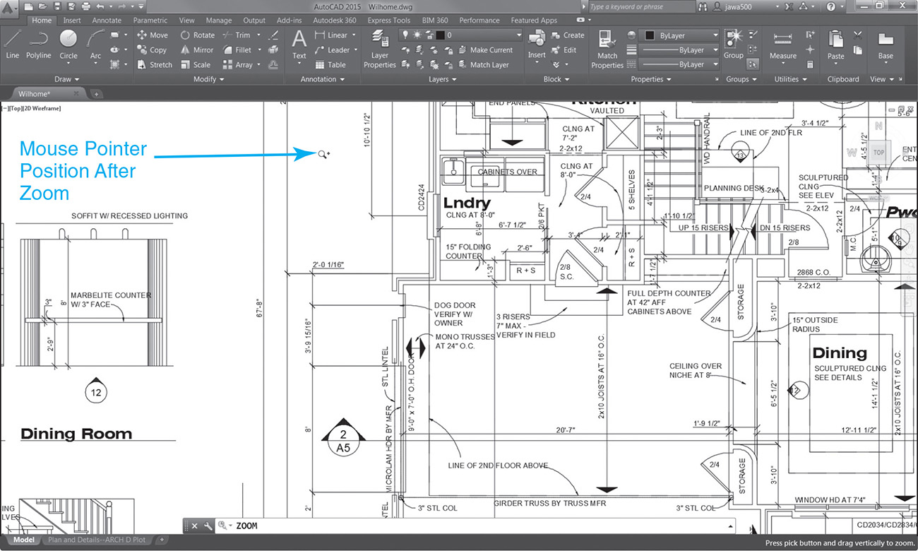
After you select the Pan tool, your mouse pointer changes to the hand icon shown in Figure 3-7.

Using the Pan tool, you simply grab on to the drawing with your “hand” by clicking with your mouse and then drag the drawing across the drawing display window by holding the mouse button down. See Figures 3-8A and 3-8B.
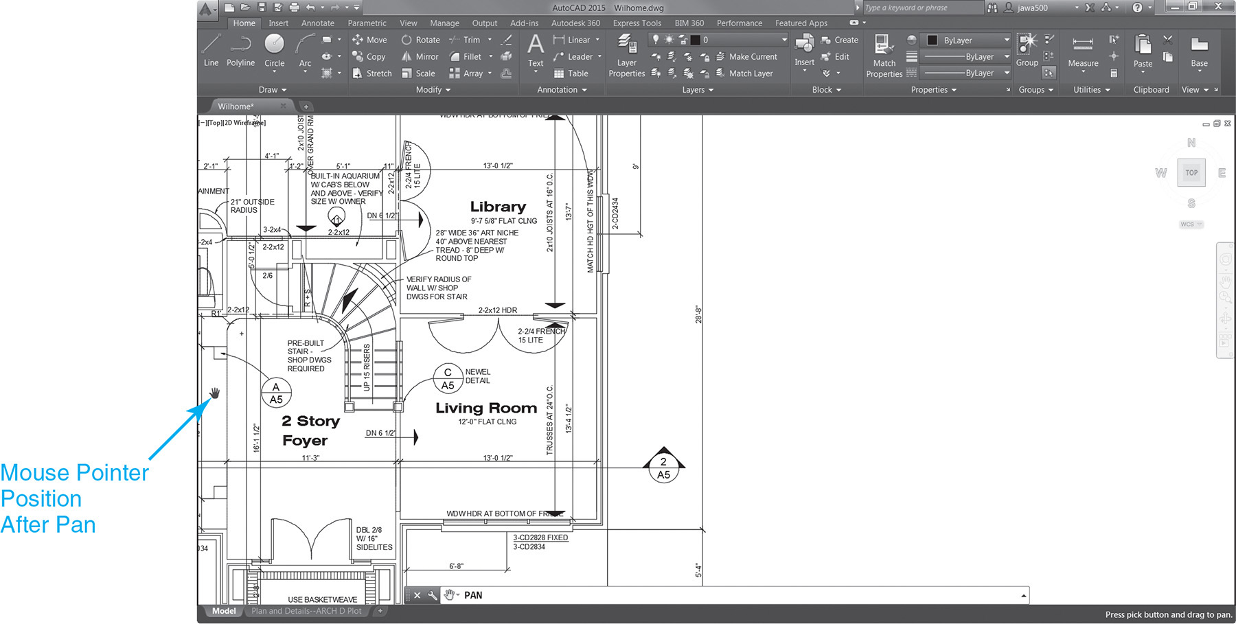
As with the Zoom Realtime tool, if you run out of mouse pad during the process of moving your mouse across the screen, just pick up your mouse, reposition it, and repeat the process. When you are finished panning and the drawing display contains the desired drawing information, press <Enter> or <Esc> to complete the panning process.
Tip
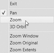
You can quickly switch between the Pan tool and the Zoom Realtime tool by right-clicking to display the shortcut menu shown in Figure 3-9.
Exercise 3-7 Using the Pan Tool
![]() Continue from Exercise 3-6.
Continue from Exercise 3-6.
![]() Zoom in on the drawing using any of the techniques explained earlier.
Zoom in on the drawing using any of the techniques explained earlier.
![]() Select the Pan tool on the navigation bar.
Select the Pan tool on the navigation bar.
![]() The mouse pointer changes to a hand icon (see Figure 3-7), and AutoCAD prompts you at the command line:
The mouse pointer changes to a hand icon (see Figure 3-7), and AutoCAD prompts you at the command line:
Press ESC or ENTER to exit, or right-click to display shortcut menu.
![]() Place your mouse pointer at the right edge of the drawing display window.
Place your mouse pointer at the right edge of the drawing display window.
![]() Click with your mouse and drag the drawing display to the left by holding down the mouse button.
Click with your mouse and drag the drawing display to the left by holding down the mouse button.
![]() Release the left mouse button and then click the right mouse button to display the Pan/Zoom shortcut menu (see Figure 3-9).
Release the left mouse button and then click the right mouse button to display the Pan/Zoom shortcut menu (see Figure 3-9).
![]() Select Zoom from the menu to switch to the Zoom Realtime tool.
Select Zoom from the menu to switch to the Zoom Realtime tool.
![]() Zoom in and out of the drawing a few times using the Zoom Realtime tool.
Zoom in and out of the drawing a few times using the Zoom Realtime tool.
![]() Right-click with the mouse to display the Pan/Zoom shortcut menu again.
Right-click with the mouse to display the Pan/Zoom shortcut menu again.
![]() Select Exit from the menu to end the command.
Select Exit from the menu to end the command.
Using the Middle Mouse Button
As alluded to earlier in the section “Zooming In and Out of a Drawing,” you can also use the wheel on a mouse as a button to either activate the Pan tool or display the Object Snap shortcut menu. The MBUTTONPAN system variable determines whether the Pan tool is activated or the Object Snap shortcut menu is displayed. It has the following settings:
MBUTTONPAN = 0: Object Snap shortcut menu displayed
MBUTTONPAN = 1: Pan tool activated (Default)
Exercise 3-8 Using the Middle Mouse Button to Pan
![]() Continue from Exercise 3-7.
Continue from Exercise 3-7.
![]() Select the Zoom Extents tool and zoom to the extents of the drawing.
Select the Zoom Extents tool and zoom to the extents of the drawing.
![]() Zoom in on the drawing using any of the techniques explained earlier.
Zoom in on the drawing using any of the techniques explained earlier.
![]() Click the center mouse button or mouse wheel and hold it down. The mouse pointer changes to the hand icon (see Figure 3-7).
Click the center mouse button or mouse wheel and hold it down. The mouse pointer changes to the hand icon (see Figure 3-7).
![]() Hold the button down and pan back and forth in your drawing.
Hold the button down and pan back and forth in your drawing.
![]() Release the button.
Release the button.
![]() Hold down the <Ctrl> key on your keyboard.
Hold down the <Ctrl> key on your keyboard.
![]() Click the center mouse button or mouse wheel and hold it down. The mouse pointer changes to the joystick icon (see Figure 3-10).
Click the center mouse button or mouse wheel and hold it down. The mouse pointer changes to the joystick icon (see Figure 3-10).

![]() Hold the button down and pan around in your drawing.
Hold the button down and pan around in your drawing.
In order to do this exercise you must have a mouse with a center button or a thumb wheel, and the MBUTTONPAN system variable must be set to 1.
Tip
Holding down the <Ctrl> key when you use the middle button of your mouse to activate the Pan tool will put you in “joystick” mode (see Figure 3-10) so that the mouse pointer acts like a game joystick.
Panning and Zooming Transparently
One of best things about the Pan and Zoom display tools is that you can use them transparently.
transparent command: A command that can be used without interrupting the currently active command.
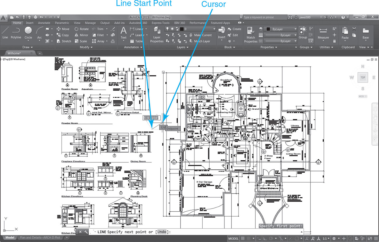
This ability allows you to pan and zoom in the middle of drawing or editing. For instance, you can begin drawing a line by selecting the first point in an overall view (see Figure 3-11A), use the Zoom Window tool to zoom closer to your work, and select the endpoint (see Figure 3-11B).
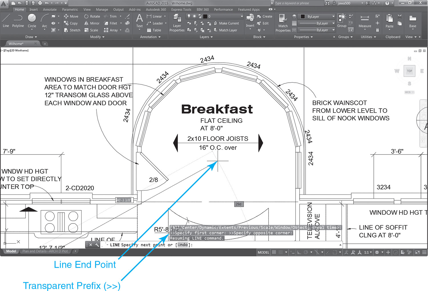
Check out the command line window in Figure 3-11B. When you are prompted for the corner points to define the window area, both prompts are preceded with double arrows (>>) to indicate the command is transparent. After the zoom process is complete and control passes back to the LINE command, AutoCAD displays the following prompt at the command line:
Resuming the LINE command.
The transparent display commands can be used in conjunction with almost every draw or modify command and can substantially increase both your precision and your productivity.
Exercise 3-9 Panning and Zooming Transparently
![]() Continue from Exercise 3-8.
Continue from Exercise 3-8.
![]() Select the Zoom Extents tool and zoom to the extents of the drawing.
Select the Zoom Extents tool and zoom to the extents of the drawing.
![]() Select the Line tool from the Draw panel. AutoCAD prompts you:
Select the Line tool from the Draw panel. AutoCAD prompts you:
Specify first point:
![]() Pick a point in your drawing to begin the line (see Figure 3-11A).
Pick a point in your drawing to begin the line (see Figure 3-11A).
![]() Select any of the Zoom or Pan tools explained so far in this chapter.
Select any of the Zoom or Pan tools explained so far in this chapter.
![]() Zoom and pan around your drawing and change the drawing display.
Zoom and pan around your drawing and change the drawing display.
![]() Exit out of the ZOOM or PAN command. AutoCAD prompts you to select the next point of the line (see Figure 3-11B):
Exit out of the ZOOM or PAN command. AutoCAD prompts you to select the next point of the line (see Figure 3-11B):
Resuming LINE command.
Specify next point or [Undo]:
![]() Pick the next point for the line and press <Enter> to end the LINE command.
Pick the next point for the line and press <Enter> to end the LINE command.
Note
The wheel mouse Pan and Zoom Realtime tools described earlier also work transparently.
Tip
By default, multiple consecutive zoom and pan operations are grouped into a single operation. Grouping zoom and pan operations together minimizes the steps required to return to previous views, saving time and increasing productivity. You can turn this feature on and off via the Combine zoom and pan commands check box in the Undo/Redo area at the bottom right of the User Preferences tab of the Options dialog box.
Cleaning Up the Drawing Display
Occasionally it is necessary to “clean up” or refresh the drawing display area so that objects appear correctly. Information on layers that were frozen and then thawed may not appear in some cases, and the display smoothness of arc and circle objects can look jagged. AutoCAD provides a way to “regenerate” the display, but only via command line entry using the commands described in the following section.
The REGEN Command
The REGEN command recalculates, or regenerates, your drawing display, updating all drawing objects. Information that is on layers that did not reappear after a layer was thawed is redisplayed, and all curved objects such as circles, arcs, and splines are recalculated so that they appear much smoother.
Figure 3-12 shows what occasionally happens when you zoom in on a circle after being zoomed out in a drawing.
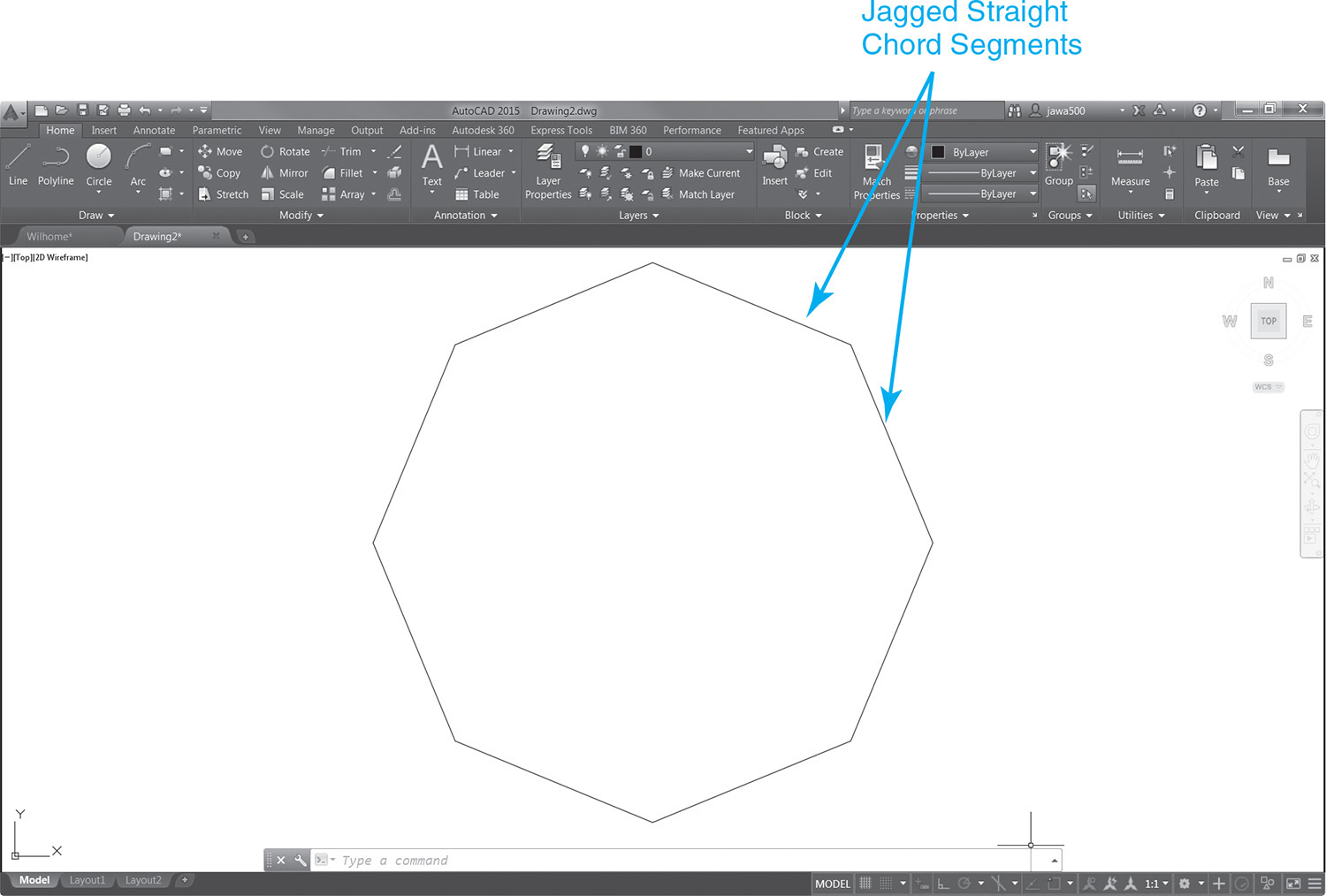
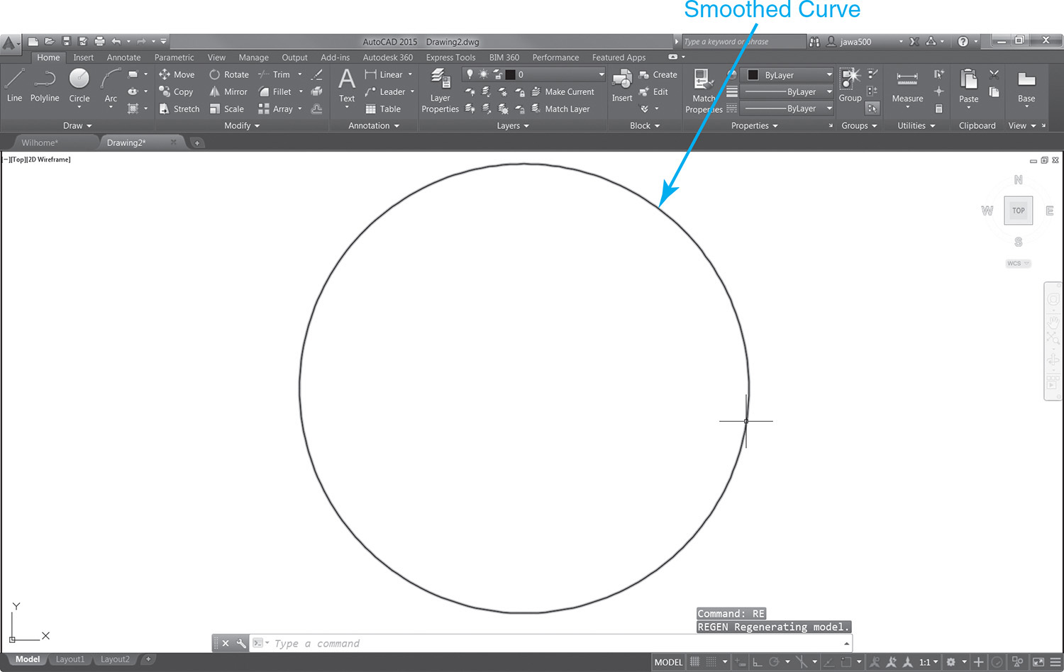
AutoCAD approximates the curve using straight chord segments. This approximation is done primarily to accelerate display performance. To smooth out the curve, you can enter REGEN<Enter>, or RE<Enter>, at the AutoCAD command line. Entering either will totally recalculate the display so that the curve is smoothed out as shown in Figure 3-13.
Exercise 3-10 Regenerating the Drawing Display
![]() Start a new drawing using the acad.dwt drawing template.
Start a new drawing using the acad.dwt drawing template.
![]() Select the Zoom All tool to zoom to the limits of the drawing.
Select the Zoom All tool to zoom to the limits of the drawing.
![]() Draw a tiny circle at the center of the drawing display using the CIRCLE command introduced in Chapter 2.
Draw a tiny circle at the center of the drawing display using the CIRCLE command introduced in Chapter 2.
![]() Select the Zoom Window tool and zoom in so the circle fills the drawing display.
Select the Zoom Window tool and zoom in so the circle fills the drawing display.
![]() The perimeter of the circle should appear jagged (see Figure 3-12).
The perimeter of the circle should appear jagged (see Figure 3-12).
![]() Type RE<Enter> at the AutoCAD command line to run the REGEN command.
Type RE<Enter> at the AutoCAD command line to run the REGEN command.
![]() The drawing display is regenerated so that the perimeter of the circle is now smooth (see Figure 3-13).
The drawing display is regenerated so that the perimeter of the circle is now smooth (see Figure 3-13).
The Clean Screen Toggle
The Clean Screen toggle temporarily turns off the ribbon and any palettes so that you have more room to draw because sometimes the screen can get a bit cluttered (see Figure 3-14).
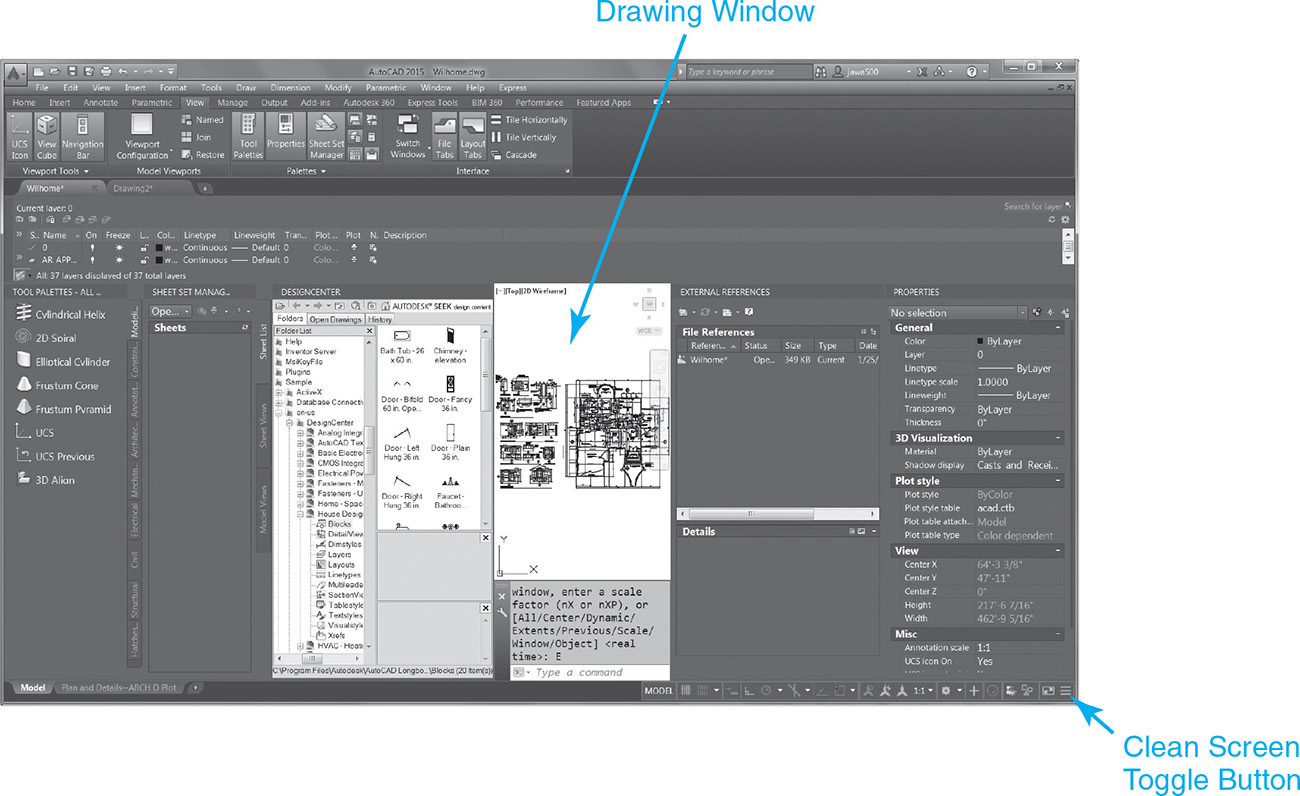
Figure 3-14 is an extreme example of what your screen might look like if you turned on every AutoCAD palette. Fortunately, AutoCAD provides a way out of this mess.
The CLEANSCREENON command turns the ribbon and palettes off, and the CLEANSCREENOFF command turns them back on. You can toggle Clean Screen on and off by clicking on the button on the right side of the status bar, as shown in Figure 3-14.
Selecting Clean Screen will turn off the ribbon and palettes and maximize your drawing area as shown in Figure 3-15.
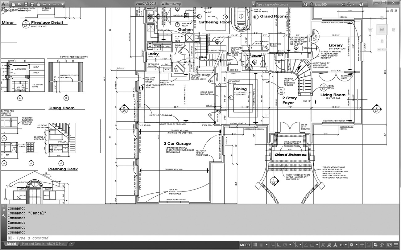
When Clean Screen is turned on, your drawing display is maximized to completely fill your Windows desktop so that the Windows taskbar is no longer available. You must turn Clean Screen off to access the Windows taskbar again.
Tip
You can also use the <Ctrl>+0 keyboard combination to toggle Clean Screen on and off.
Exercise 3-11 Toggling Clean Screen On and Off
![]() Continue from Exercise 3-10.
Continue from Exercise 3-10.
![]() Select the Clean Screen button on the right side of the status bar.
Select the Clean Screen button on the right side of the status bar.
![]() The ribbon and any palettes are temporarily turned off, and the drawing display area is increased.
The ribbon and any palettes are temporarily turned off, and the drawing display area is increased.
![]() Select the Clean Screen button on the status bar again.
Select the Clean Screen button on the status bar again.
![]() The ribbon and any palettes that were turned off are turned back on again, and the drawing display returns to its previous size.
The ribbon and any palettes that were turned off are turned back on again, and the drawing display returns to its previous size.
![]() Use the <Ctrl>+0 keyboard combination to turn Clean Screen on and off again.
Use the <Ctrl>+0 keyboard combination to turn Clean Screen on and off again.
Drawing Display Resolution and Performance
There are a number of AutoCAD settings that can be used to control the resolution of drawing objects on your screen and, in turn, enhance your computer’s performance when regenerating the drawing display. With the advent of high-performance computers and workstations, some of the settings described in this section have lost a little significance.
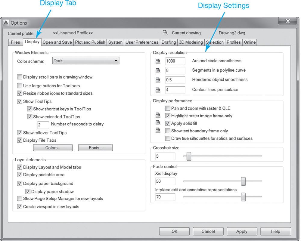
All the display settings can be managed on the Display tab of the Options dialog box (see Figure 3-16).
Controlling Arc and Circle Smoothness
AutoCAD uses short vectors, or chords, to represent radial geometry such as arcs, circles, ellipses, and splines on the drawing display. These chords are not typically noticeable until you zoom in on a curved surface like a circle without regenerating your drawing (see Figure 3-12).
The number of chords used to represent a curve and determine its smoothness is controlled via the Arc and circle smoothness setting on the Display tab of the Options dialog box shown in Figure 3-16. Settings can range from 1 to 20,000. The default setting is 1000. Setting this number higher makes curved surfaces appear smoother by increasing the number of vectors used to represent each curve. This increased resolution does come at a cost in performance, however. The higher the number, the longer it takes to regenerate your drawing.
Exercise 3-12 Controlling Arc and Circle Smoothness
![]() Continue from Exercise 3-11.
Continue from Exercise 3-11.
![]() Select the Options button from the bottom of the application menu list to display the Options dialog box.
Select the Options button from the bottom of the application menu list to display the Options dialog box.
![]() Increase the Arc and circle smoothness setting in the Display resolution area at the top right of the dialog box from the default value of 1000 to 10,000.
Increase the Arc and circle smoothness setting in the Display resolution area at the top right of the dialog box from the default value of 1000 to 10,000.
![]() Select OK to close the Options dialog box and return to the drawing.
Select OK to close the Options dialog box and return to the drawing.
![]() Select the Zoom Extents tool to zoom to the limits of the drawing.
Select the Zoom Extents tool to zoom to the limits of the drawing.
![]() Draw a tiny circle at the center of the drawing display using the CIRCLE command introduced in Chapter 2.
Draw a tiny circle at the center of the drawing display using the CIRCLE command introduced in Chapter 2.
![]() Select the Zoom Window tool and zoom in so the circle fills the drawing display (see Figure 3-12).
Select the Zoom Window tool and zoom in so the circle fills the drawing display (see Figure 3-12).
![]() The perimeter of the circle should appear smooth (see Figure 3-13).
The perimeter of the circle should appear smooth (see Figure 3-13).
Note
The Arc and circle smoothness setting can also be controlled via the VIEWRES command. Type VIEWRES at the AutoCAD command line and enter a value between 1 and 20,000. This VIEWRES setting is saved with the drawing.
Turning Text Display On and Off
Text is one of the most resource-intensive object types in an AutoCAD drawing because of its detail. If you have a large drawing with lots of text (see Figure 3-17A), regenerating a drawing can become a time-consuming task. To help, AutoCAD provides a way to turn text off in a drawing so that only a boundary frame outline of the text is visible (see Figure 3-17B).

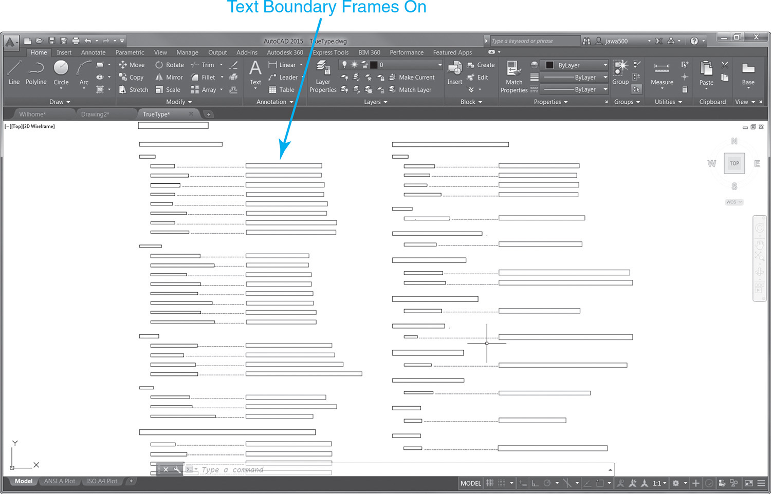
This allows you to still locate each text object in a drawing but not have to regenerate it in finite detail. To turn off text display in a drawing, select the Show text boundary frame only check box on the Display tab of the Options dialog box shown in Figure 3-16. After turning the text display off, you must regenerate the drawing in order to see the results.
Exercise 3-13 Turning Text Display On and Off
![]() Open drawing Willhome located in the student data files.
Open drawing Willhome located in the student data files.
To access student data files, go to www.pearsondesigncentral.com.
![]() Select the Model tab so that model space is active.
Select the Model tab so that model space is active.
![]() Select the Zoom Extents tool and zoom to the extents of the drawing.
Select the Zoom Extents tool and zoom to the extents of the drawing.
![]() Select the Options button from the bottom of the application menu to display the Options dialog box.
Select the Options button from the bottom of the application menu to display the Options dialog box.
![]() Select the Display tab.
Select the Display tab.
![]() Select the Show text boundary frame only option in the Display performance area at the middle right of the dialog box so it is turned on (checked).
Select the Show text boundary frame only option in the Display performance area at the middle right of the dialog box so it is turned on (checked).
![]() Select OK to close the Options dialog box and return to the drawing.
Select OK to close the Options dialog box and return to the drawing.
![]() Zoom in on an area of the drawing that contains text.
Zoom in on an area of the drawing that contains text.
![]() Type RE<Enter> to run the REGEN command.
Type RE<Enter> to run the REGEN command.
![]() All text is turned off so only the rectangular boundary frames are visible.
All text is turned off so only the rectangular boundary frames are visible.
![]() Select the Options button from the bottom of the application menu to display the Options dialog box.
Select the Options button from the bottom of the application menu to display the Options dialog box.
![]() Select the Display tab.
Select the Display tab.
![]() Select the Show text boundary frame only option in the Display performance area at the middle right of the dialog box so it is turned off (unchecked).
Select the Show text boundary frame only option in the Display performance area at the middle right of the dialog box so it is turned off (unchecked).
![]() Select OK to close the Options dialog box and return to the drawing.
Select OK to close the Options dialog box and return to the drawing.
![]() Select the Zoom Extents tool and zoom to the extents of the drawing.
Select the Zoom Extents tool and zoom to the extents of the drawing.
![]() Type RE<Enter> at the AutoCAD command line to run the REGEN command.
Type RE<Enter> at the AutoCAD command line to run the REGEN command.
![]() All text is turned back on so it is visible.
All text is turned back on so it is visible.
The Show text boundary frame only setting can also be controlled via the QTEXTMODE system variable. Setting QTEXTMODE = 1 turns off text display and turns on text boundary frames. Setting QTEXTMODE = 0 will turn text back on in a drawing. This QTEXTMODE setting is saved with the drawing.
Turning Fills On and Off
Like text, hatch patterns and solid filled areas are also very resource-intensive. Many hatched and/or solid filled areas in a drawing can significantly increase the time it takes to regenerate the drawing display. Fortunately, you can turn off hatch patterns and solid fills by deselecting (unchecking) the Apply solid fill check box on the Display tab of the Options dialog box shown in Figure 3-16. After turning solid fill areas off, you must regenerate the drawing in order to see the results.
Exercise 3-14 Turning Fill Areas On and Off
![]() Open drawing Plot Screening and Fill Areas located in the student data files.
Open drawing Plot Screening and Fill Areas located in the student data files.
To access student data files, go to www.pearsondesigncentral.com.
![]() Select the Model tab so that model space is active.
Select the Model tab so that model space is active.
![]() Select the Zoom Extents tool and zoom to the extents of the drawing.
Select the Zoom Extents tool and zoom to the extents of the drawing.
![]() Select the Options button from the bottom of the application menu to display the Options dialog box.
Select the Options button from the bottom of the application menu to display the Options dialog box.
![]() Select the Display tab.
Select the Display tab.
![]() Select the Apply solid fill option in the Display performance area at the middle right of the dialog box so that it is turned off (unchecked).
Select the Apply solid fill option in the Display performance area at the middle right of the dialog box so that it is turned off (unchecked).
![]() Select OK to close the Options dialog box and return to the drawing.
Select OK to close the Options dialog box and return to the drawing.
![]() Type RE<Enter> at the AutoCAD command line to run the REGEN command.
Type RE<Enter> at the AutoCAD command line to run the REGEN command.
![]() All filled areas are now turned off.
All filled areas are now turned off.
![]() Select the Options button from the bottom of the application menu again to display the Options dialog box.
Select the Options button from the bottom of the application menu again to display the Options dialog box.
![]() Select the Display tab.
Select the Display tab.
![]() Select the Apply solid fill option in the Display performance area at the middle right of the dialog box so that it is turned on (checked).
Select the Apply solid fill option in the Display performance area at the middle right of the dialog box so that it is turned on (checked).
![]() Select OK to close the Options dialog box and return to the drawing.
Select OK to close the Options dialog box and return to the drawing.
![]() Type RE<Enter> at the AutoCAD command line to run the REGEN command.
Type RE<Enter> at the AutoCAD command line to run the REGEN command.
![]() All filled areas are now turned back on.
All filled areas are now turned back on.
Note
The Apply solid fill setting can also be controlled via the FILLMODE system variable. Setting FILLMODE = 0 turns off hatching, solid fills, gradient fills, and wide polylines. Setting FILLMODE = 1 turns hatching, solid fills, gradient fills, and wide polylines back on in a drawing. This FILLMODE setting is saved with the drawing.
Controlling Line Smoothness
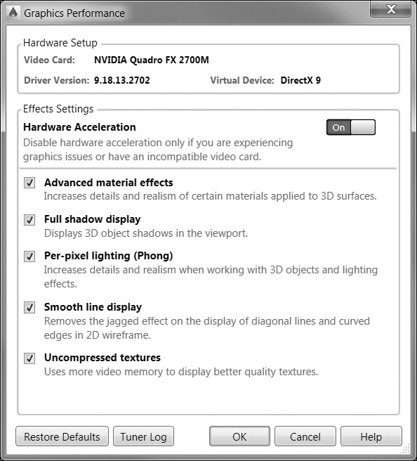
The LINESMOOTHING system variable allows you to control anti-aliasing in 2D drawings. When turned on, objects such as lines, arcs, circles, and drawing tools like grid lines, look smoother, especially when drawn at an angle. You can also turn on line smoothing by selecting the Smooth line display option in the Graphics Performance dialog box shown in Figure 3-18.

Chapter Summary
Mastering the drawing display tools and settings explained in this chapter will help to make you a more productive and precise drafter. The navigation bar on the right side of the drawing window provides you quick and easy access to all the Zoom and Pan tools you will ever need to get around in your drawings. Because there is not one display tool that provides all of the ideal functionality, practice using a combination of different tools to navigate around your drawing as you are working. You might find that you are more comfortable with some tools than others.
Sometimes it is necessary to clean up the drawing display so that arcs and circles appear smooth and you are sure all of the drawing information is displayed correctly. Typically, this requires that you enter the REGEN command via the keyboard. To help reduce the need to regenerate the display as often, you can adjust the display settings via the Display tab of the Options dialog box and optimize drawing performance.
Chapter Test Questions
Multiple Choice
Circle the correct answer.
1. To make drawing objects appear larger on the screen, you should:
a. Zoom out
b. Zoom in
c. Get a bigger computer monitor
d. Pan
2. The Zoom tools are located on the:
a. Navigation bar
b. Status bar
c. Application menu
d. None of the above
3. The Zoom Realtime tool allows you to:
a. Zoom in and zoom out
b. Zoom interactively
c. Draw faster
d. All of the above
4. The Zoom Window tool zooms in your drawing when you:
a. Choose a view
b. Pick two points
c. Pick one point
d. Specify a scale factor
5. To move the drawing display area back and forth without changing the drawing’s zoom scale factor, you should use:
a. Pan tool
b. Middle mouse button
c. Scroll bars
d. All of the above
6. The system variable that controls whether the middle mouse button activates the Pan tool is:
a. MOUSEPANBUTTON
b. MIDDLEBUTTONPAN
c. MBUTTONPAN
d. MPAN
7. Entering a command transparently allows you to:
a. Not see the command at the command line interface
b. Use the command while another command is already active
c. Temporarily turn off the drawing display
d. All of the above
8. Double-clicking the mouse wheel will:
a. Display the Object Snap shortcut menu
b. Put the mouse in joystick mode
c. Pan the display
d. Zoom extents
9. The Clean Screen toggle allows you to:
a. Minimize the drawing window
b. Turn off the ribbon and palettes
c. Erase all objects displayed on the screen
d. Clear smudge marks off your screen
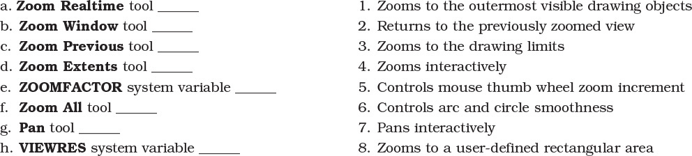
Matching
Write the number of the correct answer on the line.
True or False
Circle the correct answer.
1. True or False: The mouse pointer changes from an arrow to a microscope when the Zoom Realtime tool is selected.
2. True or False: If you zoom in as far as you can using the Zoom Realtime tool and you cannot zoom any farther, you should use the REGEN command to recalculate your display.
3. True or False: The Zoom Previous tool will also undo the last command.
4. True or False: The mouse wheel button always activates the Pan tool.
5. True or False: It is possible to zoom past the extents of a drawing using the Zoom All tool.
6. True or False: When zooming using the mouse wheel, each click of the wheel zooms in or out by 10%.
7. True or False: The mouse pointer changes from an arrow to a hand when the Pan tool is selected.
8. True or False: Any command can be used transparently when another command is active.
1. Open drawing Willhome located in the student data files.
To access student data files, go to www.pearsondesigncentral.com.
2. Select the Model tab so that model space is active.
3. Select the Zoom Extents tool, and zoom to the extents of the drawing.
4. Use the Zoom Object tool to zoom in on the “Breakfast” room label text at the top of the floor plan.
5. Double-click on the text and change it to “Breakfast Nook” using the Edit Text dialog box.
6. Zoom to the extents of the drawing.
7. Turn off the text display so only the text boundary boxes are visible.
8. Regenerate the drawing.
9. Turn off all solid fill areas.
10. Regenerate the drawing.
11. Increase the arc and circle smoothness factor to 10,000.
12. Regenerate the drawing.
13. Turn Smooth line display off and on using the LINESMOOTHNESS system variable and compare the difference.
14. Save the drawing as P3-1.