
Chapter 2. Quick Start Tutorial
• Switch between model space and layout space
• Draw some basic AutoCAD objects
• Toggle the Snap Mode, Ortho Mode, Polar Tracking, and Grid Mode drawing tools on and off
• Examine and change object properties
• Create drawing layers and move objects from one layer to another
• Add basic dimensions
• Make some basic modifications to your drawing
• Add text to your drawing
• Set up and plot your drawing
Introduction
This chapter will give you an overview of a typical AutoCAD drawing session. You examine some of the basic operations you will do on a day-to-day basis when using AutoCAD, including starting an AutoCAD session, drawing and modifying some objects, and saving and plotting your drawing. All the topics touched on in this chapter will be explained in greater detail in the following chapters. Let’s start by creating a new drawing.
Creating a New Drawing
When you start a new drawing in AutoCAD, it places you in a blank drawing by default. This blank drawing is based on a number of default AutoCAD settings, which are stored in a drawing template. In addition to this default template, AutoCAD gives you other templates to choose from, which can save you time in setting up your drawing.
drawing template: A drawing used as a starting point when creating a new drawing. Drawing templates can contain page layouts, borders, title blocks, layer settings, and many other settings or drawing objects you use on a regular basis.
Using a Template
AutoCAD provides a number of predefined templates with default settings for various drawing disciplines. These drawing templates typically have title blocks in them and predefined settings for text, dimensioning, and plotting. You can also create your own templates or save any drawing as a template.

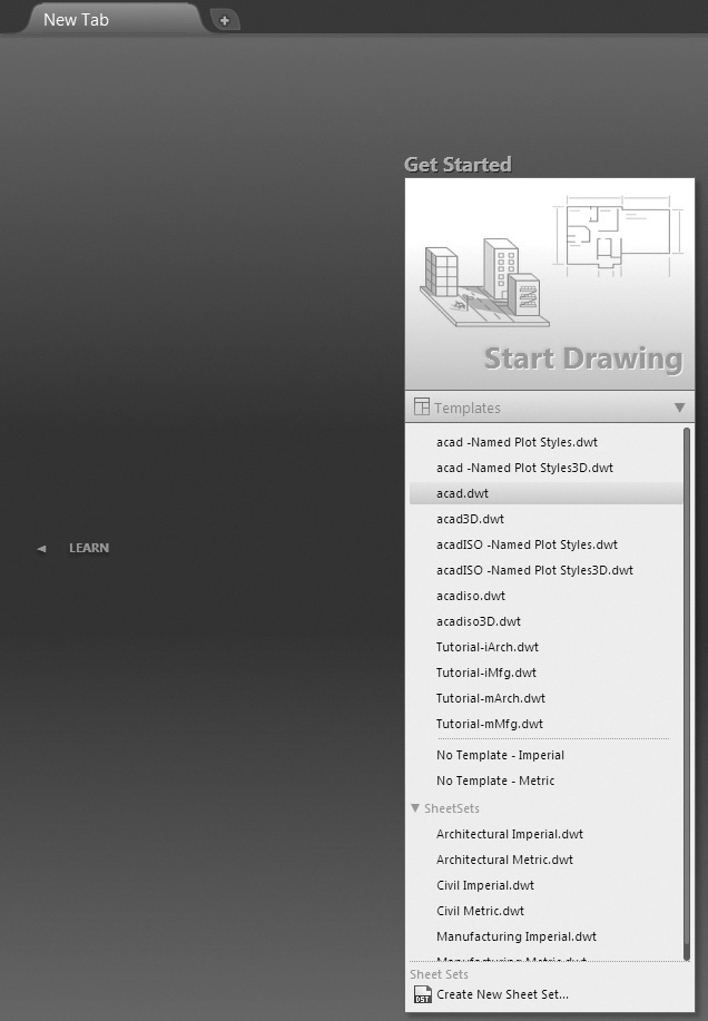
You can start a new drawing based on one of the predefined templates by selecting the Templates drop-down menu under Start Drawing on the left of the New Tab to display the Templates list (see Figure 2-1).
Saving Your Work
When you create a new drawing using a template, it is initially named Drawing followed by an incremental number (Drawing1.dwg, Drawing2.dwg, Drawing3.dwg, etc.), indicating its place in the series when it was created. The drawing does not exist as a file on your computer or network until you save it at least once by selecting Save from the Quick Access toolbar, which runs the QSAVE command.
Note
The template files that contain “ISO” in the file name are set up for metric units. In fact, the acadiso.dwt template is the default metric template.
The QSAVE command is short for “Quick Save,” although it is not so quick the first time you use it. The first time you use QSAVE, the standard Windows Save Drawing As file dialog box shown in Figure 2-2 is displayed so that you can give the drawing a file name and folder location to store the file on your computer or network. Subsequent use of the QSAVE command simply updates the file in its specified location, hence the “Quick” part.

Select the drive or device where you want to save the file by selecting it from the Save in: drop-down list at the top, and navigate to the desired folder using the Explorer-type interface in the middle. Enter the drawing name in the File name: list box or select a previous name from the drop-down list. Select the Save button to save the drawing in the specified folder and close the dialog box.
Tip
You can use the SAVEAS command to save your drawing to a new location or to change the file name. You can access the SAVEAS command by choosing Save As... from the Quick Access toolbar. In addition to changing the location and name of your file, the SAVEAS command allows you to save your drawing to an earlier version of AutoCAD or to convert it to a DXF (Design eXchange Format) file. This allows you to share your drawing data with earlier versions of AutoCAD or with other CAD packages. You can also use the SAVEAS command to save your drawing as a drawing template. See Chapter 18 for more on file formats and exchanging drawing data.
For More Details
See page 14 in Chapter 1 for more information about naming drawing files and the other AutoCAD file types.
Now that the drawing is named, each time you use the QSAVE command from now on, by clicking on the Save icon on the Quick Access toolbar, AutoCAD will update the file in the specified location and overwrite the last saved version. You should save your drawing often using the QSAVE command to ensure that you don’t lose too much work if an unexpected and/or catastrophic failure occurs. A good rule of thumb is to save your drawing every 10 to 15 minutes. Get in the habit of choosing Save from the Quick Access toolbar or by using the <Ctrl>+S keyboard combination.
Tip
By default, the current file name and path is always displayed in the title bar at the top of the AutoCAD window. Keeping your eye on the title bar after a drawing is saved is a good way to keep track of the file you’re currently working on.
File Safety Precautions
After you save a drawing once, every time you use the QSAVE command thereafter, a backup of the previous saved version of the drawing is saved in the same location with the same name as the drawing, except with a .BAK file extension. This feature allows you to recover drawing information up until the last time you saved it if for some reason this is necessary. In order to open the backup file you must either rename the .BAK extension to .DWG or use the Drawing Recovery Manager.
As double insurance, AutoCAD automatically saves your drawing at preset intervals to the Windows Temporary folder using a file name that consists of the drawing name followed by six numbers generated by AutoCAD and the file extension .SV$. The default interval between saves is 10 minutes. In order to restore an automatically saved file with the .SV$ extension, you must either rename the extension to .DWG or use the Drawing Recovery Manager.
Both the backup copy and automatic save options can be changed via the File Safety Precaution settings found on the bottom left of the Open and Save tab of the Options dialog box introduced on page 22 in Chapter 1. It is recommended that you leave both features on. Someday you will be glad you did!
Note
The automatic save feature is meant to be used as a fail-safe so that you can recover drawing information when things go wrong. It should not be relied on as a primary means of saving your work. In fact because the automatic save files (.SV$) are saved to the Windows Temporary folder, their life span is unpredictable, and they may be deleted at any time.
Tip
The Drawing Recovery Manager typically displays automatically the next time you start AutoCAD after a system crash so you can restore either the backup (BAK) file or the autosave file if they are available. To display the Drawing Recovery Manager manually, you must go to the Drawing Utilities menu on the application menu (big red A).
Exercise 2-1 Setting Up a Drawing
![]() Start AutoCAD and select Start Drawing on the New Tab to open a blank drawing.
Start AutoCAD and select Start Drawing on the New Tab to open a blank drawing.
![]() Choose New from the Quick Access toolbar to display the Select template dialog box, which opens in the default AutoCAD Template folder.
Choose New from the Quick Access toolbar to display the Select template dialog box, which opens in the default AutoCAD Template folder.
To access student data files, go to www.pearsondesigncentral.com.
![]() Select the Look in: list at the top of the dialog box, and open the Chapter 2 folder in the student data files.
Select the Look in: list at the top of the dialog box, and open the Chapter 2 folder in the student data files.
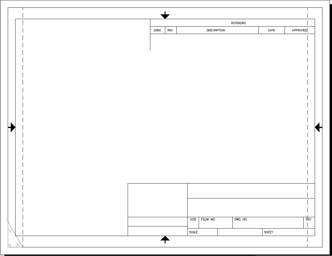
![]() Select the ansi-a.dwt template file, and select the Open button to start a new drawing with the predefined ansi-a title block shown in Figure 2-3.
Select the ansi-a.dwt template file, and select the Open button to start a new drawing with the predefined ansi-a title block shown in Figure 2-3.
![]() Choose the Save button from the Quick Access toolbar, and save your drawing as CH2_EXERCISE using the Save Drawing As file dialog box shown in Figure 2-2.
Choose the Save button from the Quick Access toolbar, and save your drawing as CH2_EXERCISE using the Save Drawing As file dialog box shown in Figure 2-2.
Model Space and Layout Space
Chapter 1 discussed AutoCAD’s two distinct drawing environments, model space and layout space. Generally speaking, model space is used for creating the geometry of your drawing. Objects that exist in the physical world (walls, doors, mechanical parts, etc.) are generally drawn in model space. Objects that exist only on a piece of paper (annotation, dimensions, notes, title blocks, etc.) are generally placed in layout space. Each drawing has only one model space but can have multiple layout spaces, each with its own name.
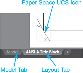
The drawing template used in this chapter has one layout named ANSI A Title Block. You can switch between model space and the layout using the tabs at the bottom of the drawing window shown in Figure 2-4.
Exercise 2-2 Switching Between Model and Layout Space
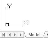
![]() Click on the Model tab. AutoCAD switches to model space, and the model space UCS icon is displayed (see Figure 2-5).
Click on the Model tab. AutoCAD switches to model space, and the model space UCS icon is displayed (see Figure 2-5).
![]() Click on the ANSI A Title Block tab. AutoCAD switches back to layout space.
Click on the ANSI A Title Block tab. AutoCAD switches back to layout space.
![]() Save your drawing.
Save your drawing.
AutoCAD’s model space looks distinctively different from layout space. There is no “edge” to the space as there is in layout space. The XY icon (called the UCS icon) looks different as well. In contrast, layout space looks like a piece of paper. The space has edges (and the appearance of a shadow along the edges), and the UCS icon looks like a page corner, as shown in Figure 2-4.
Viewports
An AutoCAD layout can be thought of as a sheet of paper with scaled views or pictures of the AutoCAD model placed on it. These views are created by creating viewports in the paper space layout. Viewports are holes or windows in the paper that look into the model space environment. You can activate viewports and make changes directly to the model space environment through the viewport.
viewport: A window in the paper space environment that shows the view of the model space environment.
The ANSI A Title Block layout contains a single viewport. In the following exercise, you’ll examine this viewport.
Exercise 2-3 Activating a Viewport
![]() Double-click with your mouse near the center of the drawing within the border outline. AutoCAD outlines the viewport so it becomes bold (see Figure 2-6).
Double-click with your mouse near the center of the drawing within the border outline. AutoCAD outlines the viewport so it becomes bold (see Figure 2-6).
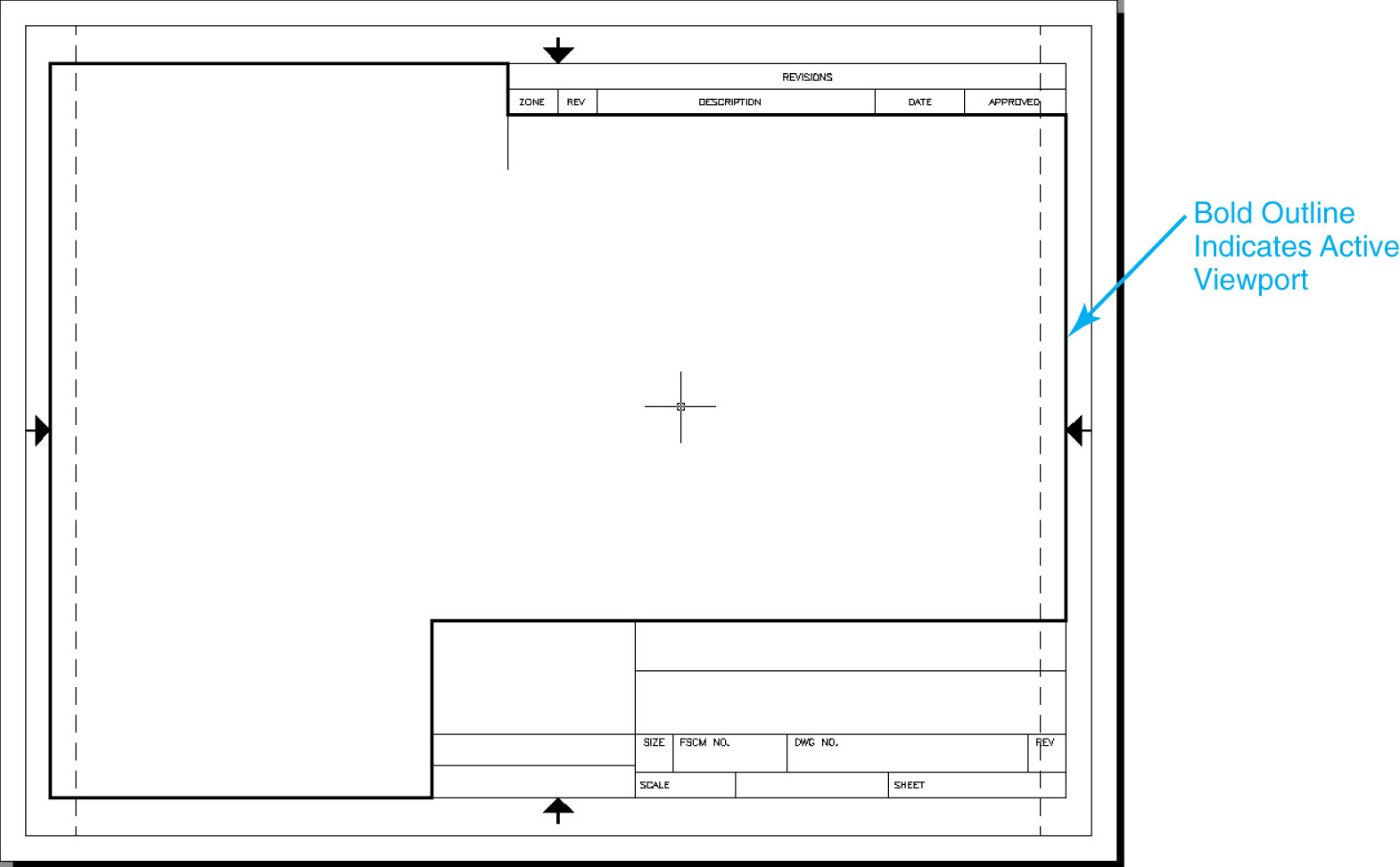
![]() Drag your mouse around the screen. Notice that the crosshairs appear only inside the viewport. When you drag the cursor outside the viewport, the crosshairs turn into a pointer.
Drag your mouse around the screen. Notice that the crosshairs appear only inside the viewport. When you drag the cursor outside the viewport, the crosshairs turn into a pointer.
![]() Double-click outside the viewport to close the viewport and return to layout space.
Double-click outside the viewport to close the viewport and return to layout space.
![]() Save your drawing.
Save your drawing.
You can also use the MODEL/PAPER button on the status bar to activate a single viewport. Switching from PAPER to MODEL makes a viewport active. Switching back to PAPER returns you to layout space.
The drawing template used in this chapter contains a single viewport; however, you can create multiple viewports in each layout.
For More Details
Chapter 14 provides detailed information about model space, paper space, layouts, and how to create and control viewports.
Communicating with AutoCAD
When you create a drawing, you are placing AutoCAD objects in the drawing. There are different types of objects (lines, arcs, circles, text, etc.). Each type of object has a unique set of properties. When you create an object, AutoCAD will ask you to specify the various aspects of that object. This is done primarily through prompts for information at both the command line window and the cursor.
objects: Graphical drawing elements, such as lines, arcs, circles, polylines, and text.
The Command Line
The command line window is at the bottom of the drawing area by default (see Figure 2-7). This is one place where AutoCAD communicates with you. When you select a tool, AutoCAD will display the command name in the command line and then prompt you for more information. The command line can be docked at the top or bottom of the drawing window and moved. It can also be turned off completely, but this is not recommended.

For More Details
See page 27 in Chapter 1 for detailed information about controlling the display of the command line window.
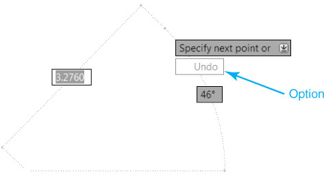
Dynamic Input
Dynamic input (see Figure 2-8) uses a command prompt that moves with your cursor and provides instant, dynamic feedback as you move around the drawing. Dynamic input provides you with active, heads-up feedback that allows you to read and respond to AutoCAD’s prompts without changing focus away from your drawing. Dynamic input can be turned on and off by toggling the Dynamic Input button on the status bar.
Whether you use dynamic input, the command line window, or both, the general process you’ll follow when creating drawing objects is:
![]() Start a command.
Start a command.
![]() Read AutoCAD’s prompt.
Read AutoCAD’s prompt.
![]() Pick points and/or respond to prompts.
Pick points and/or respond to prompts.
![]() Press <Enter> or <Esc> to end the command.
Press <Enter> or <Esc> to end the command.
Sometimes the AutoCAD prompts can be difficult to decipher. There are some general conventions that AutoCAD uses.
• AutoCAD will ask you to specify a placement point (for example, the start point of a line or arc or the center point of a circle). You can specify a placement point by picking a point on the screen, typing in a coordinate, or using an object snap.
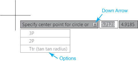
• When there are multiple ways to create an object, AutoCAD will display a down arrow next to the dynamic input prompt (see Figure 2-8). Press the down arrow key to see the list of command options.
• At the command line, options are enclosed in square brackets [ ] and are separated by a space. You specify an option by selecting it with your mouse or by typing in the blue highlighted capital letter(s) shown for that option. For example, when drawing a circle, AutoCAD gives you the following prompt and options:
Specify center point for circle or [3P 2P Ttr (tan tan radius)]:
In this example, AutoCAD is asking you either to specify the center point of the circle or to select one of three options (3P, 2P, or Ttr). To specify the Ttr option, you would either pick it with your mouse or type T and press <Enter>.
Tip
AutoCAD remembers the numerical values you enter. That means the next time you use the same command, the value you entered previously is displayed in chevrons < > so that you can simply press the <Enter> key to use the value again.
For More Details
See Chapter 4 for more on coordinate entry methods and all the specifics on the CIRCLE command and its options.
Keep in mind that when you specify a point or select an option, AutoCAD will continue to ask you for more information until it has everything it needs to create that object.
![]() Select the Model tab to switch to model space.
Select the Model tab to switch to model space.
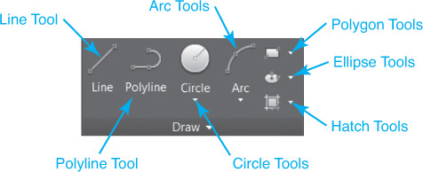
![]() Choose the Line tool from the Draw panel (see Figure 2-9). AutoCAD prompts you to Specify first point:.
Choose the Line tool from the Draw panel (see Figure 2-9). AutoCAD prompts you to Specify first point:.
![]() Look at the command line. AutoCAD shows the following:
Look at the command line. AutoCAD shows the following:
LINE Specify first point:
LINE is the command you started when you chose the Line tool. AutoCAD is asking where you want to start the line.
![]() Pick anywhere on the screen to start the line. You should now have a rubber-band line extending from the first point you specified along with dynamic information about the length and direction of the rubber-band line (see Figure 2-10).
Pick anywhere on the screen to start the line. You should now have a rubber-band line extending from the first point you specified along with dynamic information about the length and direction of the rubber-band line (see Figure 2-10).
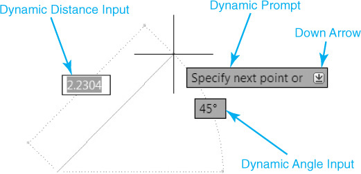
rubber band: A live preview of a drawing object as it is being drawn. The rubber-band preview allows you to see objects as they are being created.
![]() AutoCAD prompts you to Specify next point or
AutoCAD prompts you to Specify next point or ![]() . The down arrow indicates that a command option is available. Press the down arrow key, and you’ll see the Undo option appear (see Figure 2-11).
. The down arrow indicates that a command option is available. Press the down arrow key, and you’ll see the Undo option appear (see Figure 2-11).
![]() Look again at the command line. It shows:
Look again at the command line. It shows:
LINE Specify next point or [Undo]:
You can now either specify the next point on the line, choose the Undo option from the dynamic display, pick the Undo option from the command line with your mouse, or type U<Enter> to undo that point.
![]() Pick another point anywhere on the screen. AutoCAD will draw a single line segment and automatically start drawing another line segment. AutoCAD again prompts you to Specify next point or
Pick another point anywhere on the screen. AutoCAD will draw a single line segment and automatically start drawing another line segment. AutoCAD again prompts you to Specify next point or ![]() .
.
![]() Press the down arrow, and select Undo from the option list. The second point you specified is “undone,” and the rubber-band line is now extending from the first point you selected.
Press the down arrow, and select Undo from the option list. The second point you specified is “undone,” and the rubber-band line is now extending from the first point you selected.
![]() AutoCAD again prompts you to Specify next point or
AutoCAD again prompts you to Specify next point or ![]() . Pick another point on the screen. AutoCAD draws that line segment and repeats the prompt.
. Pick another point on the screen. AutoCAD draws that line segment and repeats the prompt.
![]() Press <Esc> to end the LINE command.
Press <Esc> to end the LINE command.
![]() Save your drawing.
Save your drawing.
The dynamic input at the cursor should disappear, and you should now see the prompt “Type a command” displayed at the command line. This is AutoCAD’s way of letting you know that it is idle and ready for the next command.
Tip
You can repeat the last command you used by pressing either <Enter> or the spacebar at the command prompt. In most cases, AutoCAD interprets pressing the spacebar the same as pressing <Enter>. The exception to this is when you are typing in a line of text where spaces are expected.
Object Snaps, Ortho Mode, and Polar Tracking
Because precision is important, AutoCAD can look for key points on objects and select those points automatically. These key points are known as object snaps or osnaps.
By default, AutoCAD will look for the endpoints of lines and arcs and the center points of circles. You can turn object snapping on and off by selecting the Object Snap button on the status bar.
object snaps/osnaps: Geometric points on objects such as the endpoints or midpoint of a line or the center of an arc or circle.
Tip
Right-click on the Object Snap button on the status bar and choose Object Snap Settings... to change the default object snap setting.
AutoCAD can help you draw perfectly vertical or horizontal lines. AutoCAD does this with both the Ortho Mode and Polar Tracking buttons. When turned on, Ortho mode (which stands for orthographic) will restrict the crosshairs movement to either horizontal or vertical movement. Ortho mode takes effect only when you are specifying a point relative to another point (when specifying the second point of a line, for example).
orthographic: 90° increments.
Tip
The <F8> key will toggle Ortho mode on and off.
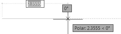
Polar tracking is similar to Ortho mode, except it simply indicates when the crosshairs are close to a vertical or horizontal angle. When you get close to these directions, AutoCAD will display an alignment path and a tooltip showing you how far and in what direction you have dragged your crosshairs (see Figure 2-12). When the alignment path is visible, the point you pick will be placed along that alignment path at the distance indicated.
polar tracking: A process in which AutoCAD will lock the cursor movement to predefined angles.
Tip
The <F10> key will toggle polar tracking on and off. By default, polar tracking is set to select angles in increments of 90°. Right-click on the Polar Tracking button on the status bar and choose Tracking Settings... to change the default increment angle and to detect specific angles to track.
For More Details
See Chapter 5 for a complete list of object snaps and how to use them and for more on using the Ortho Mode and Polar Tracking drawing tools.
Exercise 2-5 Using Object Snaps, Ortho Mode, and Polar Tracking
![]() Toggle the Object Snap button on.
Toggle the Object Snap button on.
![]() Select the Line tool from the Draw panel.
Select the Line tool from the Draw panel.
![]() Move the crosshairs close to the start of the first line and let it sit there for a moment. A square will appear at the end of the line along with a tooltip that says Endpoint (see Figure 2-13).
Move the crosshairs close to the start of the first line and let it sit there for a moment. A square will appear at the end of the line along with a tooltip that says Endpoint (see Figure 2-13).
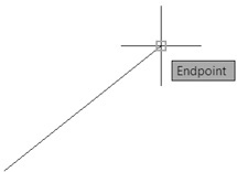
![]() Pick near the end of the line. AutoCAD will automatically select the endpoint of that line.
Pick near the end of the line. AutoCAD will automatically select the endpoint of that line.
![]() Toggle the Polar Tracking drawing tool on.
Toggle the Polar Tracking drawing tool on.
![]() Drag the crosshairs straight up until the polar tracking appears. Notice the polar tracking shows a distance and direction (90°).
Drag the crosshairs straight up until the polar tracking appears. Notice the polar tracking shows a distance and direction (90°).
![]() Pick a point approximately 1 inch 90° above the end of the line.
Pick a point approximately 1 inch 90° above the end of the line.
![]() Toggle the Polar Tracking drawing tool off and the Ortho Mode drawing tool on.
Toggle the Polar Tracking drawing tool off and the Ortho Mode drawing tool on.
![]() Drag the crosshairs around the screen. The crosshairs are now restricted to horizontal and vertical movement only.
Drag the crosshairs around the screen. The crosshairs are now restricted to horizontal and vertical movement only.
![]() Drag the cursor to the right and type 3<Enter>. AutoCAD draws a line 3 units long to the right.
Drag the cursor to the right and type 3<Enter>. AutoCAD draws a line 3 units long to the right.
![]() Press <Esc> to end the LINE command.
Press <Esc> to end the LINE command.
![]() Save your drawing.
Save your drawing.
Note
The last line you drew was done using a method called direct distance entry. This is a combination of cursor movement and keyboard input in which you drag your cursor to indicate direction and use the keyboard to type in the distance. Direct distance input can be used any time you need to specify a coordinate location. Used with the Ortho Mode and Polar Tracking controls, it can greatly simplify coordinate entry.
direct distance entry: The process of specifying a point by dragging the AutoCAD cursor to specify direction and typing in a distance.
Undo/Redo
AutoCAD keeps a running history of all the commands you’ve issued within a single drawing session. This allows you to back up to any point in the drawing session. The UNDO command will take you back through your drawing session, one command at a time, all the way back to the start of your drawing. If you go back too far, the REDO command will move you forward, one command at a time, until you’ve restored everything.
![]() From the Quick Access toolbar, choose Undo (or press <Ctrl>+Z). The lines created with the previous LINE command will disappear. Look at the command prompt, and see that the lines were undone. The Redo button is now active in the Quick Access toolbar.
From the Quick Access toolbar, choose Undo (or press <Ctrl>+Z). The lines created with the previous LINE command will disappear. Look at the command prompt, and see that the lines were undone. The Redo button is now active in the Quick Access toolbar.
![]() Choose the Redo tool. The lines will reappear.
Choose the Redo tool. The lines will reappear.
![]() Choose the Undo tool until all the lines are gone (model space is empty). If you go back too far (for example, back into paper space), use the Redo tool to get back to an empty model space.
Choose the Undo tool until all the lines are gone (model space is empty). If you go back too far (for example, back into paper space), use the Redo tool to get back to an empty model space.
![]() Save your drawing.
Save your drawing.
Note
The REDO command can be used only immediately after using the UNDO command. Once you use REDO and resume drawing, you cannot use the REDO command again until you use the UNDO tool.
Grid and Snap
In addition to using polar tracking and object snaps, you can also control the crosshairs movement by turning on Snap mode. Snap mode simply locks the crosshairs movement to a predefined increment.
Along with Snap mode, you can also display a visual grid on the screen. The Grid Mode button toggles the display grid on and off. The grid is simply a visual display; it does not print and does not control the cursor movement. The grid and snap settings are not the same thing and are set separately.
Tip
The <F7> key toggles Grid Mode on and off. <F9> toggles Snap Mode on and off.
Exercise 2-7 Using Grid Mode and Snap Mode
![]() Toggle the Grid Mode drawing tool off and toggle the Snap Mode drawing tool on.
Toggle the Grid Mode drawing tool off and toggle the Snap Mode drawing tool on.
![]() Move the cursor around and notice how it jumps from one point to another. The cursor is locked into .5 unit increments.
Move the cursor around and notice how it jumps from one point to another. The cursor is locked into .5 unit increments.
![]() Toggle the Grid Mode drawing tool on and toggle the Snap Mode drawing tool off. Now move your cursor around the screen and look at the coordinate readout on the cursor. Notice that the cursor is no longer jumping from point to point and is no longer locked into .5 unit increments.
Toggle the Grid Mode drawing tool on and toggle the Snap Mode drawing tool off. Now move your cursor around the screen and look at the coordinate readout on the cursor. Notice that the cursor is no longer jumping from point to point and is no longer locked into .5 unit increments.
![]() Toggle the Snap Mode drawing tool on and pick the Line tool from the Draw panel.
Toggle the Snap Mode drawing tool on and pick the Line tool from the Draw panel.
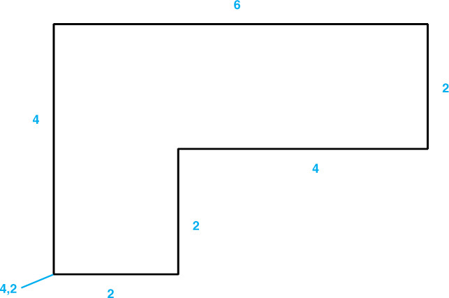
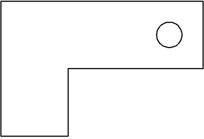
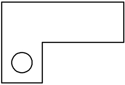
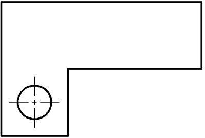
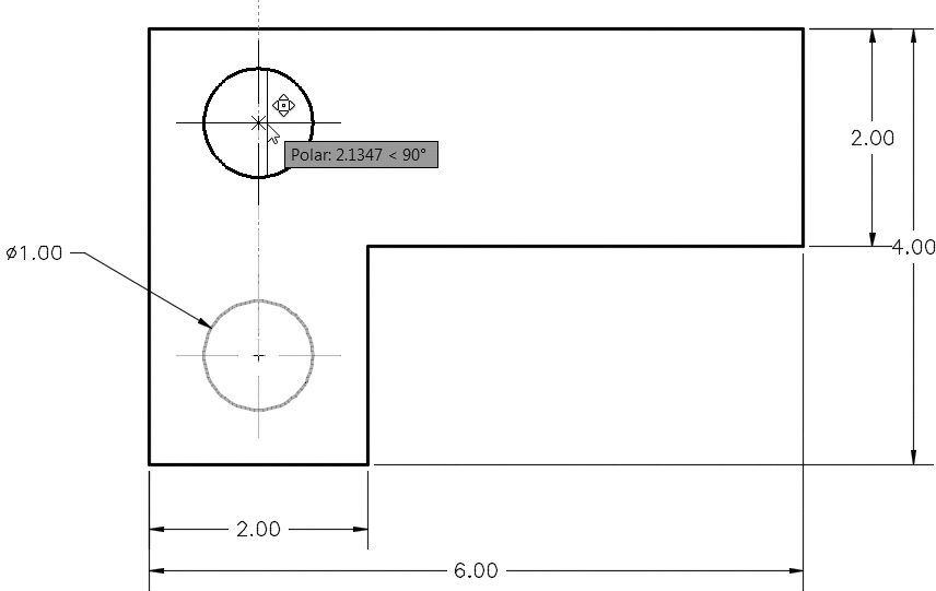
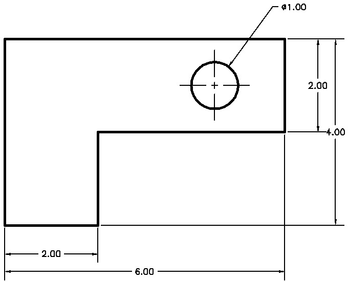
![]() Move your cursor to the coordinate 4,2 and pick that point. Continue picking points in a counterclockwise direction to draw the outline shown in Figure 2-14.
Move your cursor to the coordinate 4,2 and pick that point. Continue picking points in a counterclockwise direction to draw the outline shown in Figure 2-14.
![]() Press <Enter> or <Esc> to end the LINE command.
Press <Enter> or <Esc> to end the LINE command.
![]() Save your drawing.
Save your drawing.
Draw a Circle
Let’s add a hole to our drawing. To do that, we’ll place a circle on the drawing using the CIRCLE command.
![]() Toggle the Grid Mode and Snap Mode drawing tools off.
Toggle the Grid Mode and Snap Mode drawing tools off.
![]() Choose the Center, Radius tool from the Draw panel. AutoCAD prompts you: Specify center point for circle or
Choose the Center, Radius tool from the Draw panel. AutoCAD prompts you: Specify center point for circle or ![]() . AutoCAD is asking you to either specify a center point location or choose an option.
. AutoCAD is asking you to either specify a center point location or choose an option.
![]() Type 9,5<Enter>. AutoCAD places the center of the circle at the coordinate 9,5 and starts dragging a preview of the circle.
Type 9,5<Enter>. AutoCAD places the center of the circle at the coordinate 9,5 and starts dragging a preview of the circle.
![]() AutoCAD prompts you to Specify radius of circle or [Diameter]:. It is asking you to either specify the radius of the circle or choose an option.
AutoCAD prompts you to Specify radius of circle or [Diameter]:. It is asking you to either specify the radius of the circle or choose an option.
![]() Type 3/8<Enter> to specify a radius of 3/8″. The circle is drawn, and AutoCAD ends the CIRCLE command.
Type 3/8<Enter> to specify a radius of 3/8″. The circle is drawn, and AutoCAD ends the CIRCLE command.
![]() Save your drawing. Your drawing should now resemble Figure 2-15.
Save your drawing. Your drawing should now resemble Figure 2-15.
In the previous exercise, there were a couple of things to notice. First, when you specified the center point of the circle, you typed the coordinate instead of picking it on the screen. This is an example of absolute coordinate entry.
absolute coordinate entry: The process of specifying a point by typing in a coordinate. The coordinate is measured from the origin or 0,0 point in the drawing.
The second thing to note is that when you specified the radius of the circle you typed in a fraction (3/8) instead of the decimal number (.375). AutoCAD will accept fractions and mixed numbers (for example, 1-3/8) as well as decimal numbers.
Note
You must use a hyphen (-) to separate whole numbers and fractions as shown because the keyboard spacebar works as an <Enter> key in AutoCAD. Pressing the spacebar will simply enter the whole number value, making it impossible to enter the fractional portion.
Navigating Around the Drawing
In order to work effectively, you must be able to navigate around the drawing by controlling what is displayed on your screen. Sometimes it is necessary to zoom in close to your drawing to do detailed work, while at other times, you might need to zoom out to see the big picture. If you are zoomed in close, but the portion of the drawing you need to work on next is off the edge of the screen so it is not visible, you need to be able to shift the display to view that area of the drawing. In AutoCAD this is referred to as panning.
The easiest way to navigate around the drawing is using the Pan and Zoom tools located on the navigation bar shown in Figure 2-16.
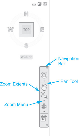
Selecting the Pan tool changes the cursor to a little hand icon that you click and drag in the drawing window to shift your display. If necessary, you can click and drag repeatedly until you reach the desired location in the drawing. When you reach the area of the drawing you want to display, press the <Enter> or <Esc> key to exit.
There are a number of Zoom tools to select from. The default Zoom tool is Zoom Extents, which is explained next. Clicking on the down arrow at the bottom of the Zoom Extents button displays the shortcut menu shown in Figure 2-17 with all of the different Zoom tools.
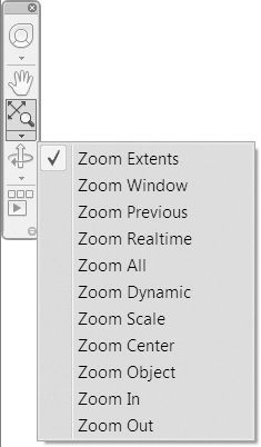
Some of the more useful Zoom tools include:
• Zoom Extents Displays everything visible in your drawing by fitting the outermost extents of your drawing information within the AutoCAD drawing window. Good command to use if you “lose” your work off the screen and you want to get it back
• Zoom Window Allows you to define a rectangular window area to zoom up on by specifying two corner points of a boundary area
• Zoom Previous Restores the previous pan/zoom display so you can back up through your pan/zoom history. It DOES NOT undo any other commands; it affects only the display. AutoCAD keeps track of up to 10 previous views
• Zoom Realtime Changes the cursor to a magnifying glass icon with a plus/minus sign indicating that you can click and drag the mouse up the screen to zoom in closer to the drawing, and click and drag the mouse down the screen to zoom out farther from the drawing
Exercise 2-9 Navigating Around the Drawing
![]() Select the Zoom Window tool from the navigation bar. AutoCAD prompts you to Specify first corner:.
Select the Zoom Window tool from the navigation bar. AutoCAD prompts you to Specify first corner:.
![]() Pick a point slightly below and to the left of the circle. AutoCAD prompts you to Specify opposite corner:.
Pick a point slightly below and to the left of the circle. AutoCAD prompts you to Specify opposite corner:.
![]() Pick a point slightly above and to the right of the circle. AutoCAD will zoom into the area you selected.
Pick a point slightly above and to the right of the circle. AutoCAD will zoom into the area you selected.
![]() Select the Zoom Previous tool from the navigation bar. AutoCAD switches back to the previous view.
Select the Zoom Previous tool from the navigation bar. AutoCAD switches back to the previous view.
![]() Select the Zoom Extents tool from the navigation bar. AutoCAD fills the display with the drawing.
Select the Zoom Extents tool from the navigation bar. AutoCAD fills the display with the drawing.
![]() Select the Zoom Previous tool again to return to the original display.
Select the Zoom Previous tool again to return to the original display.
![]() Select the Zoom Realtime tool from the navigation bar.
Select the Zoom Realtime tool from the navigation bar.
![]() Hold down the mouse button and drag your mouse up and down the screen. AutoCAD zooms in and out accordingly. Press <Esc> to exit the command.
Hold down the mouse button and drag your mouse up and down the screen. AutoCAD zooms in and out accordingly. Press <Esc> to exit the command.
![]() Select the Pan tool from the navigation bar.
Select the Pan tool from the navigation bar.
![]() Hold down the mouse button and drag your mouse back and forth across the screen. AutoCAD pans the display accordingly. Press <Esc> to exit the command.
Hold down the mouse button and drag your mouse back and forth across the screen. AutoCAD pans the display accordingly. Press <Esc> to exit the command.
![]() Using the Pan and Zoom tools, pan and zoom your drawing as needed.
Using the Pan and Zoom tools, pan and zoom your drawing as needed.
![]() Save your drawing.
Save your drawing.
Zooming with a Wheel Mouse
If you use a wheel mouse with your computer, AutoCAD will make use of the scroll wheel. When you scroll the wheel up and down, AutoCAD will zoom in and out, respectively. The zoom will be centered about the location of the cursor.
Pressing and holding down the scroll wheel allows you to dynamically pan around the drawing.
Using the scroll wheel is a system behavior and not technically a command. Because of this, you can use the dynamic zoom and pan of the scroll wheel at any time during the drawing process, even while in the middle of a command.
Object Properties
As mentioned earlier in this chapter, when you create a drawing, you are placing AutoCAD objects in the drawing. When you create an object, AutoCAD will ask you to specify the various aspects or properties of that object. Chapter 1 described how some properties are common to all objects (for example, layer and color) and other properties are unique to a given type of object (for example, the radius of a circle or the height of text).
properties: The settings that control how and where a drawing object is shown in the drawing.
Note
If you hover the cursor over an object so that the object is highlighted and pause for a second, the object type, color, layer, and linetype are displayed.
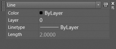
When you double-click on most objects, AutoCAD displays the Quick Properties palette. This palette displays the properties of the selected object. Figure 2-18 shows the Quick Properties palette for a line segment. If more than one object is selected, AutoCAD will show only common properties of all the selected objects. You can change the properties of any selected object by changing their values in the Quick Properties palette.
Exercise 2-10 Using the Quick Properties Palette
![]() Drag your cursor over the circle in the drawing. The circle will highlight when the cursor hovers over it, and its general properties are displayed.
Drag your cursor over the circle in the drawing. The circle will highlight when the cursor hovers over it, and its general properties are displayed.
![]() Double-click on the circle in your drawing. The circle will change color to indicate that it has been selected. Blue boxes will also appear on the circle. The Quick Properties palette will display the object properties for that circle.
Double-click on the circle in your drawing. The circle will change color to indicate that it has been selected. Blue boxes will also appear on the circle. The Quick Properties palette will display the object properties for that circle.
![]() Select the Diameter box and type 1<Enter>. The circle will immediately change its size. Notice that the values for radius, circumference, and area update as well.
Select the Diameter box and type 1<Enter>. The circle will immediately change its size. Notice that the values for radius, circumference, and area update as well.
![]() Change the Center X value to 5.
Change the Center X value to 5.
![]() Change the Center Y value to 3.
Change the Center Y value to 3.
![]() Press <Esc> to deselect the circle.
Press <Esc> to deselect the circle.
![]() Double-click on the line on the far right of the drawing. The Quick Properties palette now shows the properties for that object.
Double-click on the line on the far right of the drawing. The Quick Properties palette now shows the properties for that object.
![]() While the line is still selected, select the circle. AutoCAD now shows only the properties that are common to those two objects.
While the line is still selected, select the circle. AutoCAD now shows only the properties that are common to those two objects.
![]() Press <Esc> to clear the selection. Your drawing should resemble Figure 2-19.
Press <Esc> to clear the selection. Your drawing should resemble Figure 2-19.
![]() Save your drawing.
Save your drawing.
Tip
You can dynamically preview changes to an object before applying the changes. For example, if you select the circle in Figure 2-19 and then use the Quick Properties palette to change the color property, the circle dynamically changes color as you pass the cursor over each color in the list.
Layers
As you saw in the previous exercise, some properties are common to all objects. These include color, linetype, lineweight, layer, and transparency. Color is fairly obvious; it is the display color of the object on the screen. Linetype refers to how the line is displayed—for example, a dashed line, dotted line, or continuous line. Lineweight is the plotted width of the object (think of it as pen width). Transparency controls the visibility of objects so you can see through them.
You can assign a color, linetype, lineweight, and transparency level to each object individually; however, when your drawing grows in complexity, you can quickly find it difficult to manage each object individually. This is where layers come to the rescue.
For More Details
Page 9 in Chapter 1 provides a brief description of how layering is used in CAD. Chapter 6 provides a complete description of layers and other object properties.
Layers give you a way to group objects together logically. The objects are still separate but share common properties and can be manipulated as a group.
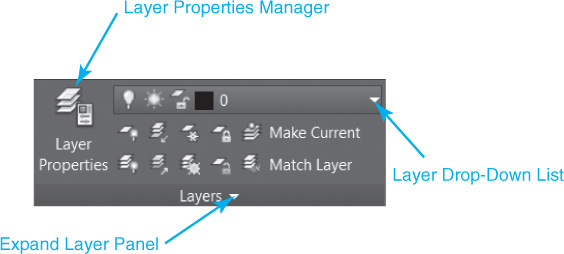
Each layer consists of a name, color, linetype, lineweight, transparency level, and a number of on/off settings. When you draw an object, the properties of the current layer are applied to that object. The quickest and easiest way to manage layers is via the Layers panel on the Home tab of the ribbon shown in Figure 2-20. The Layer drop-down list allows you to set the current drawing layer (see Figure 2-20). The Layer Properties Manager palette allows you to create and manage drawing layers.
Exercise 2-11 Creating New Layers
![]() Choose the Layer Properties tool from the Layers panel. The Layer Properties Manager palette appears (see Figure 2-21). There are three layers currently defined. Layer 0 is the default layer included in every drawing. The Title Block and Viewport layers came from the drawing template.
Choose the Layer Properties tool from the Layers panel. The Layer Properties Manager palette appears (see Figure 2-21). There are three layers currently defined. Layer 0 is the default layer included in every drawing. The Title Block and Viewport layers came from the drawing template.
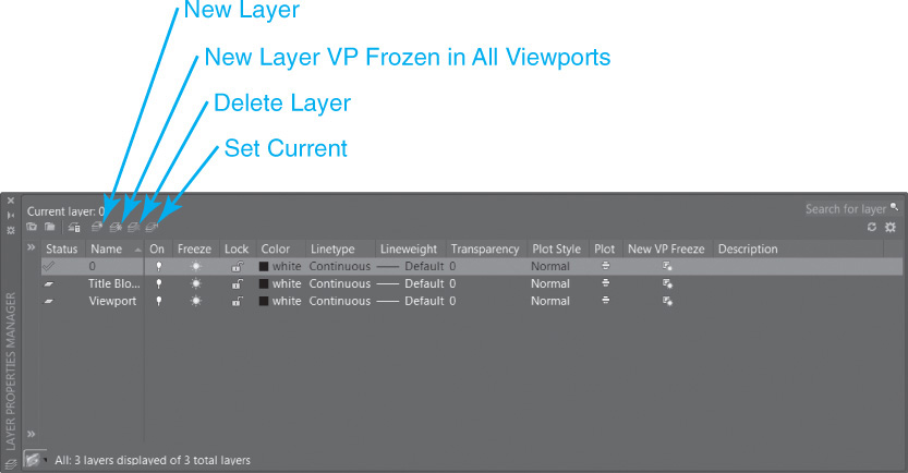
![]() Choose the New Layer button at the top of the palette (see Figure 2-21). Type Dim<Enter> for the name.
Choose the New Layer button at the top of the palette (see Figure 2-21). Type Dim<Enter> for the name.
![]() Press <Enter> again. AutoCAD will create another new layer. Type Object <Enter> for the name.
Press <Enter> again. AutoCAD will create another new layer. Type Object <Enter> for the name.
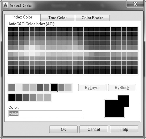
![]() Choose the color setting for the Object layer you just created. This will display the Select Color dialog box (see Figure 2-22). Choose the color red (index color 1) and choose OK to close the dialog box.
Choose the color setting for the Object layer you just created. This will display the Select Color dialog box (see Figure 2-22). Choose the color red (index color 1) and choose OK to close the dialog box.
![]() Choose the New Layer button and create a layer named Center.
Choose the New Layer button and create a layer named Center.
![]() Select the color setting for the Center layer. Set the color to blue (index color 5) and choose OK to close the Select Color dialog box.
Select the color setting for the Center layer. Set the color to blue (index color 5) and choose OK to close the Select Color dialog box.
![]() Choose the linetype setting for the Center layer. This displays the Select Linetype dialog box (see Figure 2-23).
Choose the linetype setting for the Center layer. This displays the Select Linetype dialog box (see Figure 2-23).
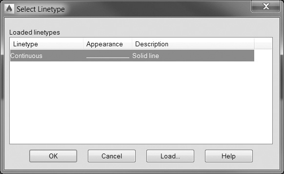
![]() Choose the Load... button. This displays the Load or Reload Linetypes dialog box (see Figure 2-24).
Choose the Load... button. This displays the Load or Reload Linetypes dialog box (see Figure 2-24).
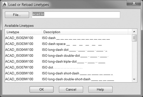
![]() Scroll down through the list to see the available linetypes. Next to each line is a text representation of what the linetype looks like. Select the CENTER2 linetype and choose OK. This loads this linetype definition into the drawing and returns you to the Select Linetype dialog box.
Scroll down through the list to see the available linetypes. Next to each line is a text representation of what the linetype looks like. Select the CENTER2 linetype and choose OK. This loads this linetype definition into the drawing and returns you to the Select Linetype dialog box.
![]() In the Select Linetype dialog box, select the CENTER2 linetype you just loaded and choose OK. This assigns the linetype you just loaded to the layer and returns you to the Layer Properties Manager palette.
In the Select Linetype dialog box, select the CENTER2 linetype you just loaded and choose OK. This assigns the linetype you just loaded to the layer and returns you to the Layer Properties Manager palette.
![]() Choose the Layer Properties button to close the Layer Properties Manager palette.
Choose the Layer Properties button to close the Layer Properties Manager palette.
![]() Save your drawing.
Save your drawing.
So far, the appearance of your drawing hasn’t changed. All you have done at this point is to define some new layers.
Exercise 2-12 Drawing on a Layer
![]() From the Layers panel, choose Center from the Layer drop-down list (see Figure 2-25). This sets the layer Center as the current drawing layer.
From the Layers panel, choose Center from the Layer drop-down list (see Figure 2-25). This sets the layer Center as the current drawing layer.
![]() Toggle the Ortho Mode drawing tool to on and choose the Line tool. Type 4.25,3<Enter> to specify the starting point.
Toggle the Ortho Mode drawing tool to on and choose the Line tool. Type 4.25,3<Enter> to specify the starting point.
![]() Drag your cursor to the right and type 1.5<Enter> to specify the length and direction of the line segment.
Drag your cursor to the right and type 1.5<Enter> to specify the length and direction of the line segment.
![]() Press <Esc> to end the LINE command.
Press <Esc> to end the LINE command.
![]() Press the spacebar to restart the LINE command. Type 5,2.25<Enter> to specify the starting point.
Press the spacebar to restart the LINE command. Type 5,2.25<Enter> to specify the starting point.
![]() Drag the cursor up and type 1.5<Enter> to specify the length and direction of the line segment.
Drag the cursor up and type 1.5<Enter> to specify the length and direction of the line segment.
![]() Press <Esc> to end the LINE command. Your drawing should now resemble Figure 2-26.
Press <Esc> to end the LINE command. Your drawing should now resemble Figure 2-26.
![]() Save your drawing.
Save your drawing.
The new lines have the color and linetype of the Center layer. The rest of the drawing was created on Layer 0. In the next exercise, you’ll move those objects from Layer 0 to the Object layer.
Exercise 2-13 Moving Objects to Another Layer
![]() In the drawing area, pick a point in a blank area below and to the left of your figure. AutoCAD prompts you to Specify opposite corner or
In the drawing area, pick a point in a blank area below and to the left of your figure. AutoCAD prompts you to Specify opposite corner or ![]() . Move your cursor up and to the right. A blue selection window will drag from the point you picked.
. Move your cursor up and to the right. A blue selection window will drag from the point you picked.
![]() Pick a point above and to the right of your figure. This will select all the objects inside the box you just specified.
Pick a point above and to the right of your figure. This will select all the objects inside the box you just specified.
![]() Hold down the <Shift> key and pick the two centerlines you just drew. This removes those lines from the selection.
Hold down the <Shift> key and pick the two centerlines you just drew. This removes those lines from the selection.
![]() Select the Object layer from the Layer drop-down list. The objects “move” to the Object layer and take on the properties of that layer.
Select the Object layer from the Layer drop-down list. The objects “move” to the Object layer and take on the properties of that layer.
![]() Press <Esc> to clear the selection.
Press <Esc> to clear the selection.
![]() Save your drawing.
Save your drawing.
Of course, the objects didn’t actually move. Their layer property was simply changed from 0 to Object. However, you can think of this as the objects “floating” from one layer to another or (in the pin-board drafting world) moving the objects from one overlay sheet to another.
Freeze and Thaw a Layer
Your drawing objects are now organized into a few logical layers. Next we’ll look at some methods of manipulating layers in your drawing.
Exercise 2-14 Freezing and Thawing Layers
![]() Select Layer 0 from the Layer drop-down list. This sets Layer 0 as the current layer.
Select Layer 0 from the Layer drop-down list. This sets Layer 0 as the current layer.
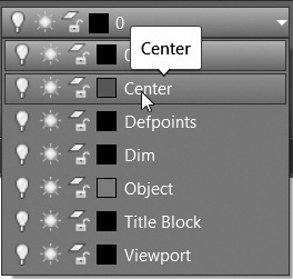
![]() From the Layer drop-down list, click on the sun icon next to layer Center (see Figure 2-27). The sun icon will change to a snowflake. Now pick anywhere in your drawing to close the Layer drop-down list. This freezes the Center layer and hides it from view.
From the Layer drop-down list, click on the sun icon next to layer Center (see Figure 2-27). The sun icon will change to a snowflake. Now pick anywhere in your drawing to close the Layer drop-down list. This freezes the Center layer and hides it from view.
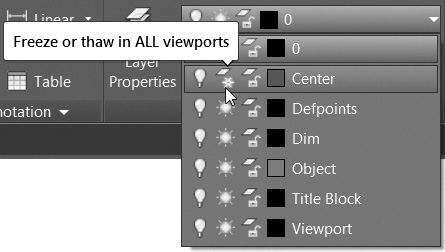
freeze/thaw: Hiding or displaying the contents of a drawing layer. Objects on a frozen layer are ignored by AutoCAD, are not shown in the drawing, and cannot be edited.
![]() From the Layer drop-down list, click on the snowflake icon next to layer Center. The snowflake now turns back to a sun. Pick anywhere in the drawing area to close the Layer drop-down list. This thaws the Center layer, making it visible again.
From the Layer drop-down list, click on the snowflake icon next to layer Center. The snowflake now turns back to a sun. Pick anywhere in the drawing area to close the Layer drop-down list. This thaws the Center layer, making it visible again.
![]() Save your drawing.
Save your drawing.
When layers are frozen, AutoCAD acts as though the objects on those layers don’t exist. Objects on frozen layers are hidden from view and cannot be changed while the layer is frozen. The current drawing layer cannot be frozen.
AutoCAD also has an On/Off setting for layers (represented by the lightbulb in the Layer drop-down list). While turning layers off will hide them from view, objects on those layers can still be modified (i.e., erased). For this reason, freezing and thawing layers is generally preferred to turning layers on and off.
Note
Unlike the Freeze option, it is possible to make a layer current that has been turned off, but it is not recommended for the simple fact that you cannot see what you are drawing.
Lock and Unlock a Layer
Although the Freeze option will prevent objects from being modified, it also hides them from view. The Lock/Unlock setting allows you to prevent objects from being modified while still keeping them displayed on screen.
Exercise 2-15 Locking and Unlocking Layers
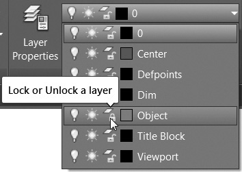
![]() From the Layer drop-down list, click on the open-lock icon next to layer Object (see Figure 2-28). The open-lock icon will change to a closed lock. Pick anywhere in your drawing to close the Layer drop-down list.
From the Layer drop-down list, click on the open-lock icon next to layer Object (see Figure 2-28). The open-lock icon will change to a closed lock. Pick anywhere in your drawing to close the Layer drop-down list.
![]() Double-click on the circle so the Quick Properties palette opens.
Double-click on the circle so the Quick Properties palette opens.
![]() Change the Radius property of the circle to 1. AutoCAD rejects the input and maintains the 0.5 Radius value.
Change the Radius property of the circle to 1. AutoCAD rejects the input and maintains the 0.5 Radius value.
![]() From the Layer drop-down list, click on the lock icon next to layer Object and pick anywhere in the drawing to close the Layer drop-down list. The Object layer is now unlocked.
From the Layer drop-down list, click on the lock icon next to layer Object and pick anywhere in the drawing to close the Layer drop-down list. The Object layer is now unlocked.
![]() Save your drawing.
Save your drawing.
This section has touched on only a few key elements of layering and AutoCAD’s layer management tools. Layer management is a crucial element of using AutoCAD effectively.
Chapter 6 explains how to use AutoCAD’s layer management tools and describes some of the issues involved in layer management.
Dimension Styles
Now that you have created a basic drawing, it’s time to dimension it. Before we start dimensioning, we need to set up the appearance of the dimensions to reflect industry standards. The look and behavior of dimensions are controlled through dimension styles. A dimension style is simply a collection of dimension settings saved with a certain name. A dimension object takes on the look and behavior of its dimension style. AutoCAD uses a dimension style called Standard as a default, but you can modify the Standard dimension style or create new ones as needed. In the following exercise, you’ll take a quick tour through some of the various dimension style settings.
dimension style: A collection of dimension settings that control how dimension objects act and are displayed.
For More Details
There are a lot of settings, and the following exercise goes through them quickly: don’t get overwhelmed. Chapter 13 gives a detailed description of dimensioning and dimension style settings.
Exercise 2-16 Changing Dimension Styles
![]() Select the Annotate tab of the ribbon to display the different annotation tools.
Select the Annotate tab of the ribbon to display the different annotation tools.
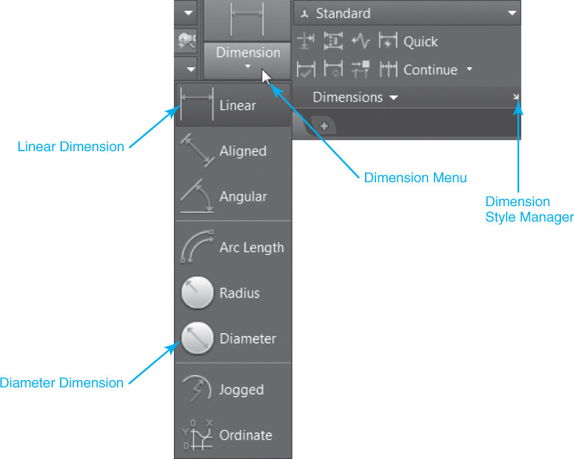
![]() Choose the Dimension Style tool from the Dimensions panel by selecting the down arrow on the right side of the panel title bar, as shown in Figure 2-29. The Dimension Style Manager dialog box appears (see Figure 2-30).
Choose the Dimension Style tool from the Dimensions panel by selecting the down arrow on the right side of the panel title bar, as shown in Figure 2-29. The Dimension Style Manager dialog box appears (see Figure 2-30).
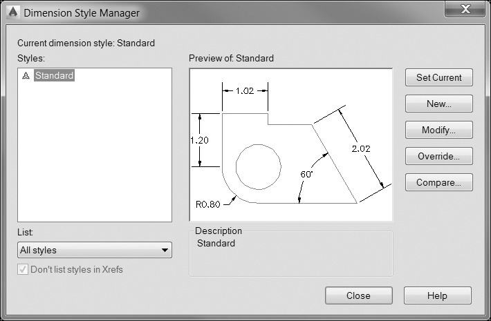
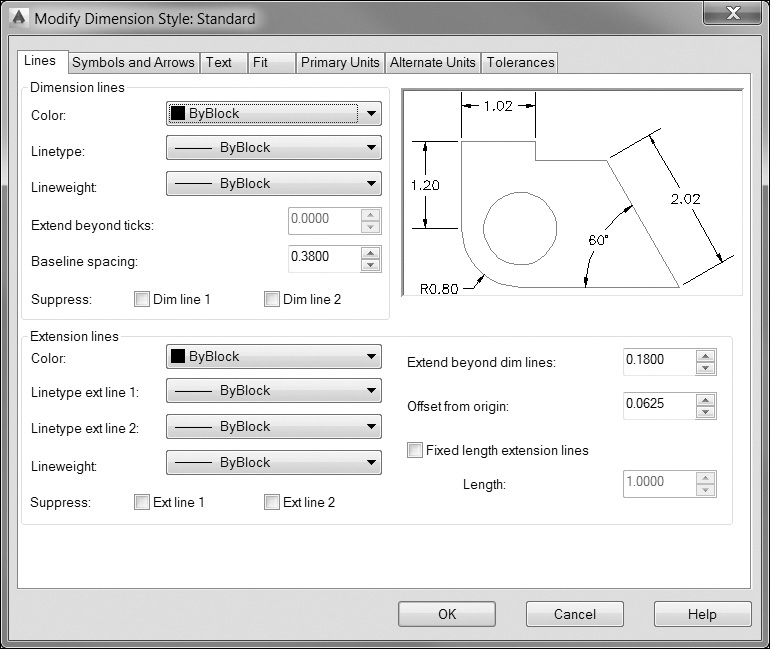
![]() Choose the Modify... button to modify the Standard dimension style. The Modify Dimension Style dialog box appears (see Figure 2-31).
Choose the Modify... button to modify the Standard dimension style. The Modify Dimension Style dialog box appears (see Figure 2-31).
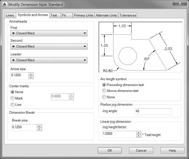
![]() Choose the Symbols and Arrows tab and change the Arrow size value to .125. In the Center marks area, change the type to None (see Figure 2-32).
Choose the Symbols and Arrows tab and change the Arrow size value to .125. In the Center marks area, change the type to None (see Figure 2-32).
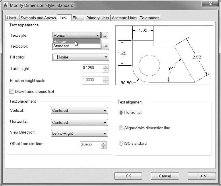
![]() Choose the Text tab and change the Text height value to .125 (see Figure 2-33).
Choose the Text tab and change the Text height value to .125 (see Figure 2-33).

![]() Click on the down arrow to the right of the Text style: drop-down list and select the Roman text style (see Figure 2-34).
Click on the down arrow to the right of the Text style: drop-down list and select the Roman text style (see Figure 2-34).
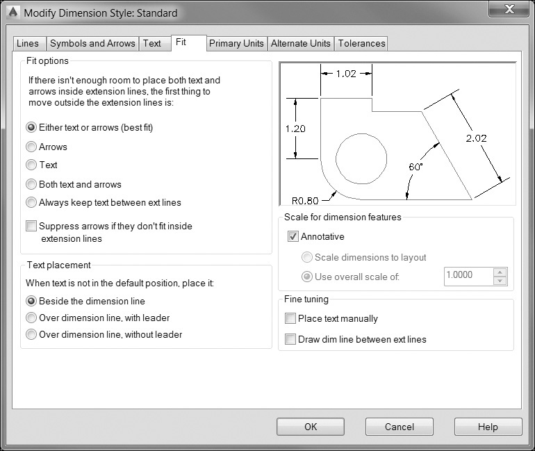
![]() Choose the Fit tab and turn on the Annotative option (see Figure 2-35).
Choose the Fit tab and turn on the Annotative option (see Figure 2-35).
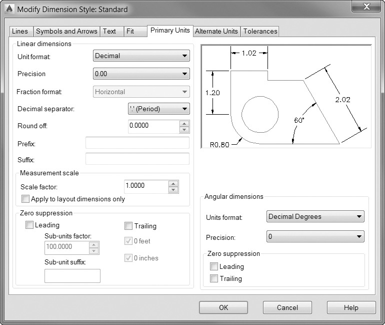
![]() Choose the Primary Units tab and select 0.00 from the Precision drop-down list (see Figure 2-36).
Choose the Primary Units tab and select 0.00 from the Precision drop-down list (see Figure 2-36).
![]() Choose OK to close the Modify Dimension Style dialog box.
Choose OK to close the Modify Dimension Style dialog box.
![]() Choose Close to close the Dimension Style Manager dialog box.
Choose Close to close the Dimension Style Manager dialog box.
![]() Save your drawing.
Save your drawing.
Due to the sheer number of options, modifying and managing dimension styles can be one of the more challenging aspects of AutoCAD. As with layers, managing dimensions and dimension styles is a crucial element of using AutoCAD effectively.
Dimensioning
AutoCAD’s dimensioning tools can easily measure distances and place dimensions on your drawing. You tell AutoCAD what type of dimension you want to place and what object or points you wish to dimension, and AutoCAD will measure and place the dimension on the drawing. You can access the dimension tools from the Dimensions panel on the Annotate tab of the ribbon shown earlier in Figure 2-29.
Exercise 2-17 Placing Dimensions
![]() Select the Home tab of the ribbon so you can access the Layers panel.
Select the Home tab of the ribbon so you can access the Layers panel.
![]() In the Layer drop-down list, set the Dim layer current.
In the Layer drop-down list, set the Dim layer current.
![]() Select the Annotate tab of the ribbon to switch back to the annotation tools.
Select the Annotate tab of the ribbon to switch back to the annotation tools.
![]() Choose the Linear tool from the Dimensions panel to start the DIMLINEAR command. AutoCAD prompts you to Specify first extension line origin or <select object>:.
Choose the Linear tool from the Dimensions panel to start the DIMLINEAR command. AutoCAD prompts you to Specify first extension line origin or <select object>:.
![]() Press <Enter> to select an object. AutoCAD prompts you to Select object to dimension:.
Press <Enter> to select an object. AutoCAD prompts you to Select object to dimension:.
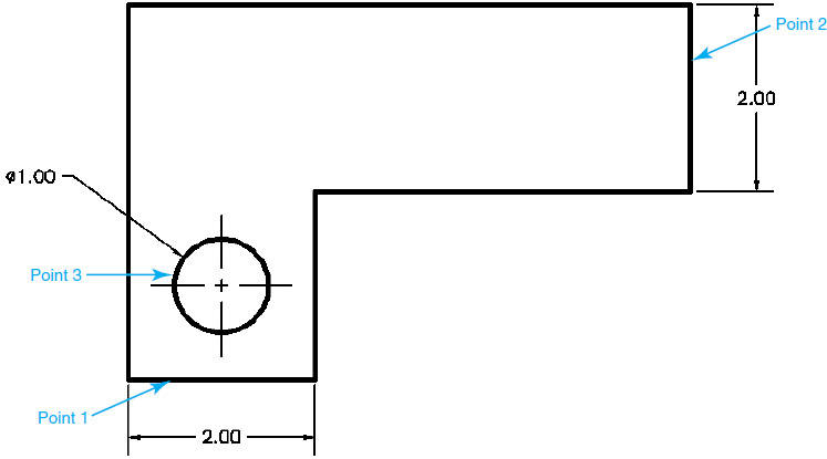
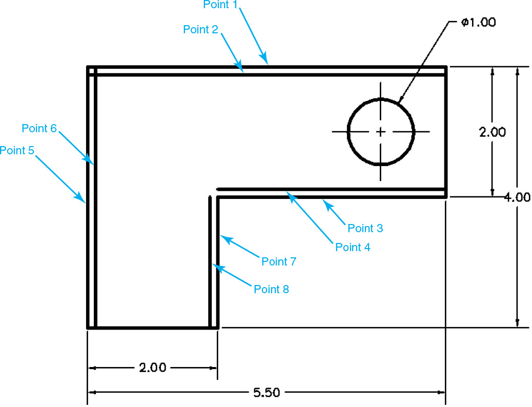
![]() Pick the line at the bottom of the drawing (point 1 in Figure 2-37). AutoCAD starts dragging a dimension from that line and prompts you to Specify dimension line location or
Pick the line at the bottom of the drawing (point 1 in Figure 2-37). AutoCAD starts dragging a dimension from that line and prompts you to Specify dimension line location or ![]() .
.
![]() Pick a point below the line. The dimension is placed, and the DIMLINEAR command ends.
Pick a point below the line. The dimension is placed, and the DIMLINEAR command ends.
![]() Press <Enter> to restart the DIMLINEAR command.
Press <Enter> to restart the DIMLINEAR command.
![]() Press <Enter> to select an object and pick the line at the right side of the drawing (point 2 in Figure 2-37).
Press <Enter> to select an object and pick the line at the right side of the drawing (point 2 in Figure 2-37).
![]() Drag the dimension to the right and pick a point to place it. The DIMLINEAR command ends.
Drag the dimension to the right and pick a point to place it. The DIMLINEAR command ends.
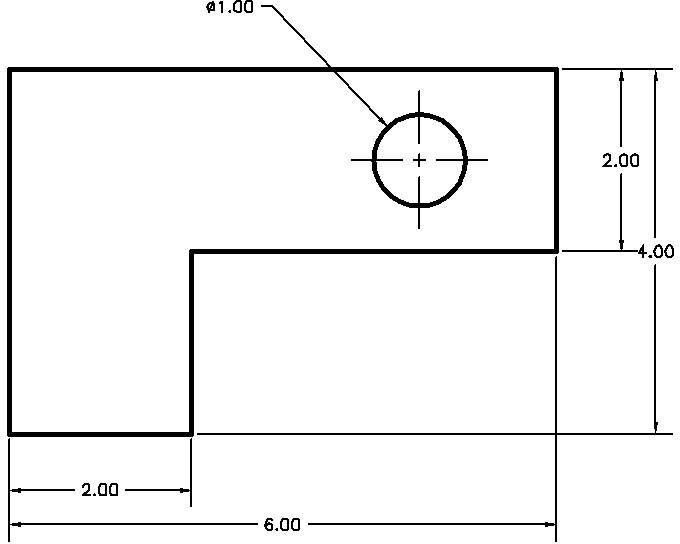
![]() From the Dimensions panel, choose Diameter to start the DIMDIAMETER command. AutoCAD prompts you to Select arc or circle:.
From the Dimensions panel, choose Diameter to start the DIMDIAMETER command. AutoCAD prompts you to Select arc or circle:.
![]() Select the circle and pick a point above and to the left of the circle (point 3 in Figure 2-37). The DIMDIAMETER command ends.
Select the circle and pick a point above and to the left of the circle (point 3 in Figure 2-37). The DIMDIAMETER command ends.
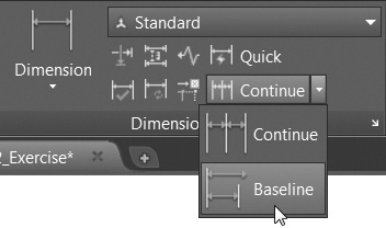
![]() Choose the Baseline tool from the Dimensions panel, as shown in Figure 2-38 to start the DIMBASELINE command. AutoCAD starts dragging a dimension from the end of the last linear dimension. AutoCAD prompts you to Specify a second extension line origin or
Choose the Baseline tool from the Dimensions panel, as shown in Figure 2-38 to start the DIMBASELINE command. AutoCAD starts dragging a dimension from the end of the last linear dimension. AutoCAD prompts you to Specify a second extension line origin or ![]() .
.
![]() Press the down arrow and choose the Select option from the menu. AutoCAD prompts you to Select base dimension:.
Press the down arrow and choose the Select option from the menu. AutoCAD prompts you to Select base dimension:.
![]() Pick the left dimension line of the first dimension you created (point 1 in Figure 2-39). A dimension line rubber-bands from the dimension you selected.
Pick the left dimension line of the first dimension you created (point 1 in Figure 2-39). A dimension line rubber-bands from the dimension you selected.
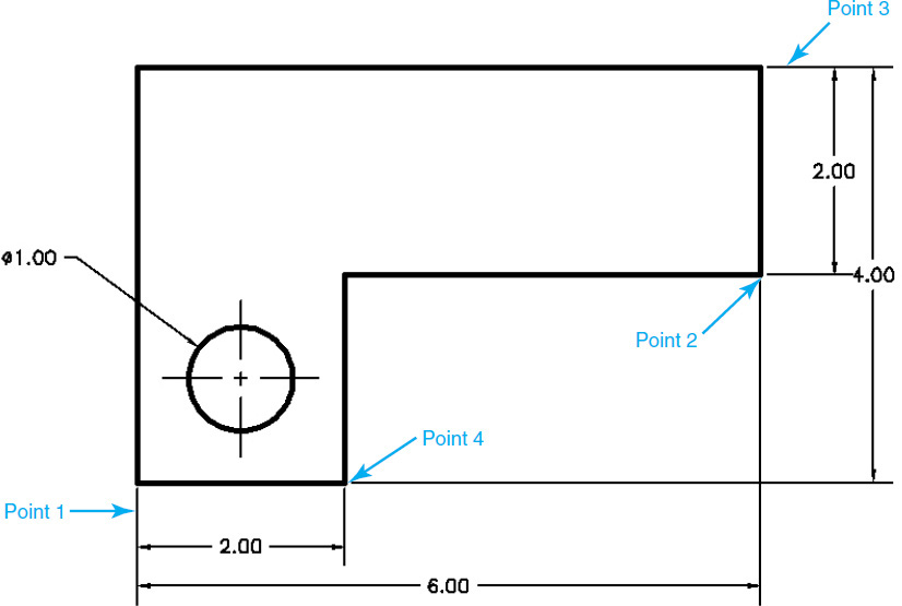
![]() Make sure your Object Snap toggle is turned on the status bar, and move your cursor near point 2 shown in Figure 2-39. When the Endpoint object snap appears, pick that point to select the endpoint of that line. AutoCAD will place the dimension and start dragging a new dimension.
Make sure your Object Snap toggle is turned on the status bar, and move your cursor near point 2 shown in Figure 2-39. When the Endpoint object snap appears, pick that point to select the endpoint of that line. AutoCAD will place the dimension and start dragging a new dimension.
![]() AutoCAD again prompts you to Specify a second extension line origin or
AutoCAD again prompts you to Specify a second extension line origin or ![]() . Press the down arrow and choose the Select option from the menu. AutoCAD prompts you to Select base dimension:.
. Press the down arrow and choose the Select option from the menu. AutoCAD prompts you to Select base dimension:.
![]() Pick the upper dimension line of the vertical dimension (point 3 in Figure 2-39).
Pick the upper dimension line of the vertical dimension (point 3 in Figure 2-39).
![]() Move your cursor near point 4 shown in Figure 2-39. When the Endpoint object snap appears, pick that point to select the endpoint of that line. AutoCAD will place the dimension and start dragging a new dimension.
Move your cursor near point 4 shown in Figure 2-39. When the Endpoint object snap appears, pick that point to select the endpoint of that line. AutoCAD will place the dimension and start dragging a new dimension.
![]() Press <Esc> to end the DIMBASELINE command.
Press <Esc> to end the DIMBASELINE command.
![]() Save your drawing.
Save your drawing.
You now have some basic dimensions on your drawing. The look and orientation of the dimensions are controlled by the dimension style.
One of the unique aspects of dimensions is their ability to update automatically as the drawing changes. This feature is called associativity, which means that dimensions are associated with the geometry and will automatically update when the geometry changes. In the next section, we’ll look at some ways to modify your drawing and see how the associative dimensions follow along.
associativity: A link between drawing objects and dimension objects. Associative dimensions will update and follow the drawing objects to which they are linked.
Modifying Drawing Objects
So far, we’ve looked at modifying object properties through the Quick Properties palette. One of the most powerful benefits of CAD systems is their unique ability to make changes to your drawing. This section introduces you to some of the basic tools used to modify your drawing.
Selection Sets
As with the drawing tools, AutoCAD has a general process for modifying objects, which is to:
![]() Select an editing tool.
Select an editing tool.
![]() Specify which object(s) you want to modify.
Specify which object(s) you want to modify.
![]() Read the prompt.
Read the prompt.
![]() Specify points and answer prompts.
Specify points and answer prompts.
![]() Press <Enter> or <Esc> to end the command.
Press <Enter> or <Esc> to end the command.
The process of specifying which objects you want to edit is called building a selection set.
building a selection set: The process of specifying the objects you wish to edit.
It is possible to preselect the objects you want to modify. If any objects are selected prior to starting a command, AutoCAD will use these objects as the selection set and will skip the Select objects: prompt.
![]() Make sure the Object Snap and Polar Tracking toggles on the status bar are turned on.
Make sure the Object Snap and Polar Tracking toggles on the status bar are turned on.
![]() Select the Home tab of the ribbon so you can access the Modify panel.
Select the Home tab of the ribbon so you can access the Modify panel.
![]() Choose the Move tool from the Modify panel on the Home tab of the ribbon. AutoCAD prompts you to Select objects:.
Choose the Move tool from the Modify panel on the Home tab of the ribbon. AutoCAD prompts you to Select objects:.
![]() Select the circle. AutoCAD again prompts you to Select objects:.
Select the circle. AutoCAD again prompts you to Select objects:.
![]() Select the two centerlines and press <Enter> to stop the selection process. AutoCAD prompts you to Specify base point or
Select the two centerlines and press <Enter> to stop the selection process. AutoCAD prompts you to Specify base point or ![]() .
.
![]() Move the cursor near the edge of the circle. When the Center object snap appears, pick that point to specify the center of the circle. AutoCAD starts dragging the objects from the center of the circle and prompts you to Specify second point of displacement or <use first point as displacement>:.
Move the cursor near the edge of the circle. When the Center object snap appears, pick that point to specify the center of the circle. AutoCAD starts dragging the objects from the center of the circle and prompts you to Specify second point of displacement or <use first point as displacement>:.
![]() Drag the object straight up until the 90° polar tracking alignment path appears (see Figure 2-40). Once it appears, type 2<Enter>. The circle, lines, and dimensions move up 2″.
Drag the object straight up until the 90° polar tracking alignment path appears (see Figure 2-40). Once it appears, type 2<Enter>. The circle, lines, and dimensions move up 2″.
![]() Save your drawing.
Save your drawing.
When you started the MOVE command, AutoCAD needed to know which objects you wanted to move. The Select objects: prompt repeated until you pressed <Enter>, telling AutoCAD you had finished selecting objects. Once you finished selecting objects, AutoCAD then went on to complete the command. It asked you to specify where you wanted to move the objects from (the base point) and where you wanted to drag the objects to (the second point).
Notice that even though you didn’t select the dimension, it moved as well. This is because of the associativity of the dimension with the circle.
Now, let’s look at selecting the objects you want to modify first and then selecting the modify command.
![]() Pick a point on the screen above and to the right of the circle (point 1 in Figure 2-41). AutoCAD will prompt you: Specify opposite corner or
Pick a point on the screen above and to the right of the circle (point 1 in Figure 2-41). AutoCAD will prompt you: Specify opposite corner or ![]() .
.
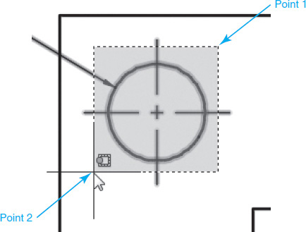
![]() Move the cursor down and to the left of the circle. AutoCAD will display a dashed rectangle with a green background from the first point you picked (see Figure 2-41). This is called a crossing window.
Move the cursor down and to the left of the circle. AutoCAD will display a dashed rectangle with a green background from the first point you picked (see Figure 2-41). This is called a crossing window.
crossing window: A method of selecting objects in a selection set by specifying a rectangular area. Anything that touches the crossing window area is selected.
![]() Pick a point below and to the left of the circle (point 2 in Figure 2-41). AutoCAD will select all the objects that are inside or touch the edge of the crossing window you picked.
Pick a point below and to the left of the circle (point 2 in Figure 2-41). AutoCAD will select all the objects that are inside or touch the edge of the crossing window you picked.
![]() Choose the Erase tool from the Modify panel. AutoCAD immediately erases the selected objects.
Choose the Erase tool from the Modify panel. AutoCAD immediately erases the selected objects.
![]() Choose the Undo tool from the Quick Access toolbar to bring the objects back.
Choose the Undo tool from the Quick Access toolbar to bring the objects back.
![]() Save your drawing.
Save your drawing.
For More Details
The crossing window is one of a number of ways to select objects. Page 269 in Chapter 7 discusses crossing windows and other ways to select objects.
Notice that AutoCAD did not prompt you to select objects. Because you selected the objects before you started the command, AutoCAD assumed that those were the objects you wanted to erase. AutoCAD doesn’t care whether you select the objects before or after you start the command. If no objects are selected, AutoCAD will simply ask you to select them before it continues with the command.
Grip Editing
You may have noticed in previous exercises that when you preselect objects, the objects highlight and little squares show up on them. These squares are known as grips. Grips appear when you select objects when there is no active command. Grips are located at strategic points on an object. For example, on a circle, grips appear at the center and the four quadrants of the circle. On lines, grips appear at the ends and midpoint of the line. On dimensions, they appear on the dimension text and the ends of the dimension lines and arrows.
grips: Editing points that appear at key locations on drawing objects.
Grips give you a quick way to modify objects by giving you access to commonly used editing commands and commonly used object points. There are five grip editing modes: Stretch, Move, Rotate, Scale, and Mirror. When you select a grip, AutoCAD starts the grip editing command and places you in Stretch mode. You can toggle between the different editing modes by pressing <Enter>. Like other commands, the grip editing modes have prompts and options.
Exercise 2-20 Editing with Grips
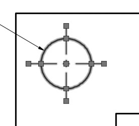
![]() Select the circle. Grips appear at the center point and the four quadrants of the circle.
Select the circle. Grips appear at the center point and the four quadrants of the circle.
![]() Select the two centerlines. Grips appear at the endpoints and midpoint of the lines. The grip at the center of the circle coincides with the midpoints of the two lines (see Figure 2-42).
Select the two centerlines. Grips appear at the endpoints and midpoint of the lines. The grip at the center of the circle coincides with the midpoints of the two lines (see Figure 2-42).
![]() Click on the center grip. The grip turns red, and AutoCAD prompts you to Specify stretch point or
Click on the center grip. The grip turns red, and AutoCAD prompts you to Specify stretch point or ![]() . AutoCAD is now in Stretch mode. AutoCAD is prompting you to specify a stretch point.
. AutoCAD is now in Stretch mode. AutoCAD is prompting you to specify a stretch point.
![]() Move your cursor to the right until the polar tracking appears. Once it appears, type 3.5<Enter>. AutoCAD moves the center of the circle 3.5″ to the right (see Figure 2-43).
Move your cursor to the right until the polar tracking appears. Once it appears, type 3.5<Enter>. AutoCAD moves the center of the circle 3.5″ to the right (see Figure 2-43).
![]() Press <Esc> to exit Grip Edit mode and clear the selection set.
Press <Esc> to exit Grip Edit mode and clear the selection set.
![]() Select the diameter dimension on the circle. Grips appear at the middle of the text and at two points on the circle.
Select the diameter dimension on the circle. Grips appear at the middle of the text and at two points on the circle.
![]() Pick the text grip and drag the text above and to the right of the circle. Pick a point outside of the drawing to place the text (see Figure 2-44).
Pick the text grip and drag the text above and to the right of the circle. Pick a point outside of the drawing to place the text (see Figure 2-44).
![]() Press <Esc> to exit Grip Edit mode and clear the selection set.
Press <Esc> to exit Grip Edit mode and clear the selection set.
![]() Save your drawing.
Save your drawing.
Notice that when you stretched the center and midpoints of the objects, the end result was that the objects moved. It’s a subtle distinction but worth noting. AutoCAD defines circles by a center point (the center grip) and a radius (the quadrant grips). Since you stretched only the center point, only the location of the circle changed, not its size. The same thing applies to the line; because you stretched just the midpoint of the line, the size and direction of the line didn’t change, only its location.
Tip
Some objects, such as dimensions, have what are referred to as multifunctional grips that provide additional modify options beyond the standard grip editing modes just described. When you select a multifunctional grip, a small pop-up menu is displayed at the cursor with the additional modify commands. You can either pick the desired multifunctional grip command from the menu with your mouse or use the <Ctrl> key to cycle through all the different options.
In the previous example, once you selected a grip, AutoCAD immediately switched to Grip Edit mode. It is possible to select multiple grips and modify them as a group. To do this, you simply hold down the <Shift> key while selecting the grips. Once you’re finished selecting grips, release the <Shift> key and then pick one of the grips to start the editing process.
Exercise 2-21 Editing with Multiple Grips
![]() Press <Esc> to cancel any active commands and clear any selections.
Press <Esc> to cancel any active commands and clear any selections.
![]() Select the three lines on the right side of the drawing (see Figure 2-45). Select the top line first.
Select the three lines on the right side of the drawing (see Figure 2-45). Select the top line first.
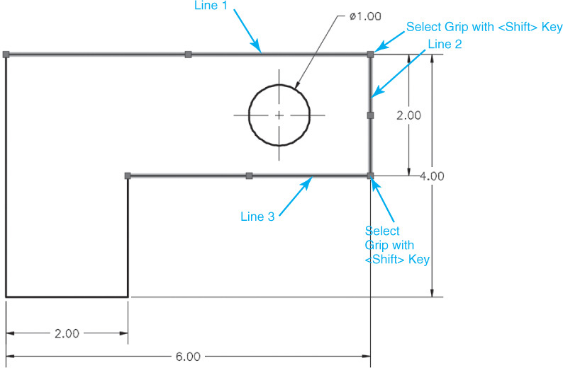
![]() Hold down the <Shift> key and select the two grips at the corners of the selected lines (see Figure 2-45). The two grips are highlighted, but grip editing has not started.
Hold down the <Shift> key and select the two grips at the corners of the selected lines (see Figure 2-45). The two grips are highlighted, but grip editing has not started.
![]() Release the <Shift> key and select either one of the highlighted grips. AutoCAD now enters Grip Edit mode.
Release the <Shift> key and select either one of the highlighted grips. AutoCAD now enters Grip Edit mode.
![]() Drag the grip to the left until the polar tracking alignment path appears at 180°. Once the polar tracking appears, type .5<Enter> into the dynamic input box (see Figure 2-46).
Drag the grip to the left until the polar tracking alignment path appears at 180°. Once the polar tracking appears, type .5<Enter> into the dynamic input box (see Figure 2-46).
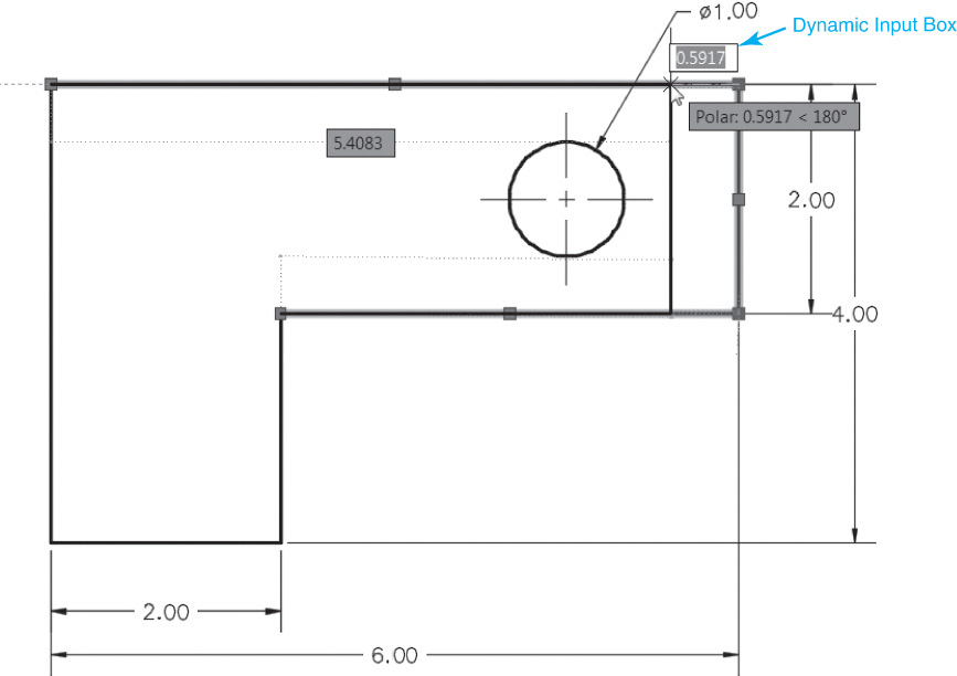
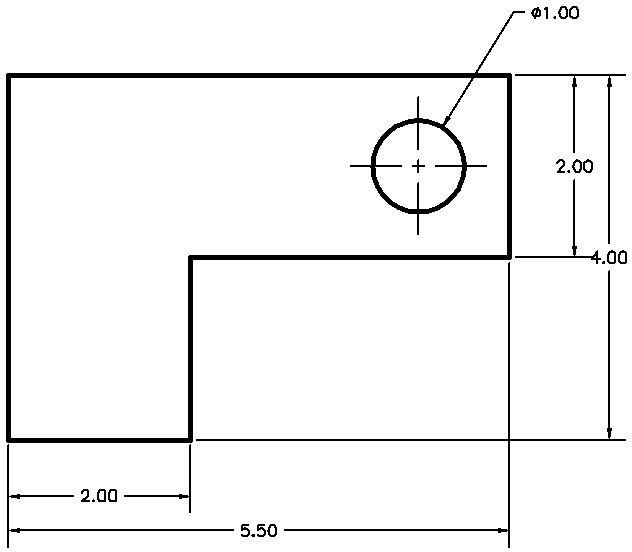
![]() AutoCAD stretches the longest line to a length of 5.5 (see Figure 2-47).
AutoCAD stretches the longest line to a length of 5.5 (see Figure 2-47).
![]() Press <Esc> to exit Grip Edit mode and clear the selection set.
Press <Esc> to exit Grip Edit mode and clear the selection set.
![]() Save your drawing.
Save your drawing.
The order in which you select the lines is important. The first line you selected determined which dimension would appear in the dynamic input box. You should have also seen the associative dimensions in action again. The dimensions updated to follow the changes in the geometry.
Introduction to Advanced Editing Techniques
A few of the advanced editing techniques are indispensable in AutoCAD. In fact, these commands and techniques are used extensively when creating AutoCAD drawings, which may seem counterintuitive. Using CAD, it is not uncommon to create a drawing by drawing more than you need and then editing and refining information to make the final product. This section introduces you to a few of these techniques.
For More Details
See Chapter 8 for more information regarding different advanced editing techniques.
Making Parallel Copies
Sometimes it is necessary to make an exact copy of a line or circle that is a specific distance from the original. This is referred to as an offset in AutoCAD. It is possible to offset a specific distance or even through a point that you specify while maintaining a copy of the original object. It is even possible to make multiple copies.
Exercise 2-22 Offsetting Objects
![]() Choose the Offset tool from the Modify panel. AutoCAD prompts you to Specify offset distance or
Choose the Offset tool from the Modify panel. AutoCAD prompts you to Specify offset distance or ![]() .
.
![]() Type .125<Enter>. AutoCAD prompts you to Select object to offset or
Type .125<Enter>. AutoCAD prompts you to Select object to offset or ![]() .
.
![]() Pick the horizontal line at the top of the drawing (point 1 in Figure 2-48). AutoCAD prompts you to Specify point on side to offset or
Pick the horizontal line at the top of the drawing (point 1 in Figure 2-48). AutoCAD prompts you to Specify point on side to offset or ![]() .
.
![]() Pick a point below that line (point 2 in Figure 2-48). AutoCAD places a copy of the line .125″ below the original. AutoCAD prompts you again to Select object to offset or
Pick a point below that line (point 2 in Figure 2-48). AutoCAD places a copy of the line .125″ below the original. AutoCAD prompts you again to Select object to offset or ![]() .
.
![]() Pick the next horizontal line down from the top of the drawing (point 3 in Figure 2-48). AutoCAD prompts you to Specify point on side to offset or
Pick the next horizontal line down from the top of the drawing (point 3 in Figure 2-48). AutoCAD prompts you to Specify point on side to offset or ![]() .
.
![]() Pick a point above that line (point 4 in Figure 2-48). AutoCAD places a copy of the line .125″ above the original. AutoCAD prompts you again to Select object to offset or
Pick a point above that line (point 4 in Figure 2-48). AutoCAD places a copy of the line .125″ above the original. AutoCAD prompts you again to Select object to offset or ![]() .
.
![]() Pick the vertical line on the left side of the drawing (point 5 in Figure 2-48). AutoCAD prompts you to Specify point on side to offset or
Pick the vertical line on the left side of the drawing (point 5 in Figure 2-48). AutoCAD prompts you to Specify point on side to offset or ![]() .
.
![]() Pick a point to the right of that line (point 6 in Figure 2-48). AutoCAD places a copy of the line .125″ to the right of the original and prompts you again to Select object to offset or
Pick a point to the right of that line (point 6 in Figure 2-48). AutoCAD places a copy of the line .125″ to the right of the original and prompts you again to Select object to offset or ![]() .
.
![]() Pick the next vertical line to the right of the drawing (point 7 in Figure 2-48). AutoCAD prompts you to Specify point on side to offset or
Pick the next vertical line to the right of the drawing (point 7 in Figure 2-48). AutoCAD prompts you to Specify point on side to offset or ![]() .
.
![]() Pick a point to the left of that line (point 8 in Figure 2-48). AutoCAD places a copy of the line .125″ to the left of the original and prompts you again to Select object to offset or
Pick a point to the left of that line (point 8 in Figure 2-48). AutoCAD places a copy of the line .125″ to the left of the original and prompts you again to Select object to offset or ![]() .
.
![]() Save your drawing.
Save your drawing.
Fixing Overlapping Lines and Closing Gaps
Often it is necessary to “clean up” lines that overlap and/or do not meet exactly so that there is a gap. Remember that the key to using AutoCAD effectively is to draw everything as precisely as possible. There is no room for even the tiniest overlap or gap. These small errors can propagate larger errors when dimensions are added or parts are mated together. AutoCAD provides a number of methods for cleaning up your drawings quickly.
Tip
When cleaning up line work it is often necessary to zoom in closer so that you can pick points precisely. The easiest way to zoom in and out is to use the mouse wheel if you have one. Otherwise, you can always use the navigation bar.
Exercise 2-23 Trimming and Extending Objects
![]() Choose the Trim tool from the Modify panel. The current command settings are displayed at the command line, and AutoCAD prompts you:
Choose the Trim tool from the Modify panel. The current command settings are displayed at the command line, and AutoCAD prompts you:
Current settings: Projection=UCS, Edge=None
Select cutting edges...
Select objects or <select all>:
![]() Select lines 1–4 shown in Figure 2-49 and press <Enter>. AutoCAD prompts you to Select object to trim or shift-select to extend or
Select lines 1–4 shown in Figure 2-49 and press <Enter>. AutoCAD prompts you to Select object to trim or shift-select to extend or ![]() .
.
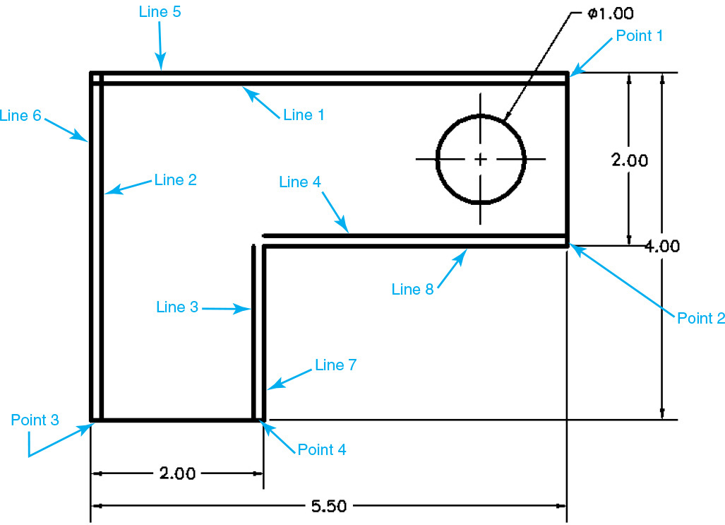
![]() Pick a point on the short line segment shown at point 1 in Figure 2-49. The vertical line is trimmed, and AutoCAD prompts you again to Select object to trim or shift-select to extend or
Pick a point on the short line segment shown at point 1 in Figure 2-49. The vertical line is trimmed, and AutoCAD prompts you again to Select object to trim or shift-select to extend or ![]() .
.
![]() Pick the line segments shown at points 2, 3, and 4 in Figure 2-49. The lines are trimmed.
Pick the line segments shown at points 2, 3, and 4 in Figure 2-49. The lines are trimmed.
![]() Press <Enter> to exit the Trim tool. Notice that the dimensions automatically update to reflect the new sizes.
Press <Enter> to exit the Trim tool. Notice that the dimensions automatically update to reflect the new sizes.
![]() Choose the Extend tool from the Modify panel. The current command settings are displayed at the command line, and AutoCAD prompts you:
Choose the Extend tool from the Modify panel. The current command settings are displayed at the command line, and AutoCAD prompts you:
Current settings: Projection=UCS, Edge=None
Select boundary edges...
Select objects or <select all>:
![]() Select lines 3 and 4 in Figure 2-49 and press <Enter>. AutoCAD prompts you to Select object to extend or shift-select to trim or
Select lines 3 and 4 in Figure 2-49 and press <Enter>. AutoCAD prompts you to Select object to extend or shift-select to trim or ![]() .
.
![]() Press the down arrow on your keyboard or type E<Enter> and select the Extend option.
Press the down arrow on your keyboard or type E<Enter> and select the Extend option.
![]() Pick a point toward the top of line 3 in Figure 2-49. The vertical line is extended, and AutoCAD prompts you again to Select object to extend or shift-select to trim or
Pick a point toward the top of line 3 in Figure 2-49. The vertical line is extended, and AutoCAD prompts you again to Select object to extend or shift-select to trim or ![]() .
.
![]() Pick a point on the left of line 4 in Figure 2-49. The line is extended.
Pick a point on the left of line 4 in Figure 2-49. The line is extended.
![]() Press <Enter> to exit the Extend tool.
Press <Enter> to exit the Extend tool.
![]() Choose the Fillet tool from the Modify panel. The current command settings are displayed at the command line, and AutoCAD prompts you:
Choose the Fillet tool from the Modify panel. The current command settings are displayed at the command line, and AutoCAD prompts you:
Current settings: Mode = TRIM, Radius = 0.0000
Select first object or ![]() .
.
![]() Select lines 1 and 2 near the upper left corner in Figure 2-49. Both lines are trimmed to form a closed corner by creating a fillet with a radius of 0.0″.
Select lines 1 and 2 near the upper left corner in Figure 2-49. Both lines are trimmed to form a closed corner by creating a fillet with a radius of 0.0″.
![]() Choose the Erase tool from the Modify panel and erase lines 5, 6, 7, and 8 (see Figure 2-49).
Choose the Erase tool from the Modify panel and erase lines 5, 6, 7, and 8 (see Figure 2-49).
![]() Your drawing should now look like Figure 2-50. Use grips to select the dimension extension line origin as shown and attach it back to the corner of the drawing using an Endpoint object snap. Make sure the Object Snap button is on.
Your drawing should now look like Figure 2-50. Use grips to select the dimension extension line origin as shown and attach it back to the corner of the drawing using an Endpoint object snap. Make sure the Object Snap button is on.
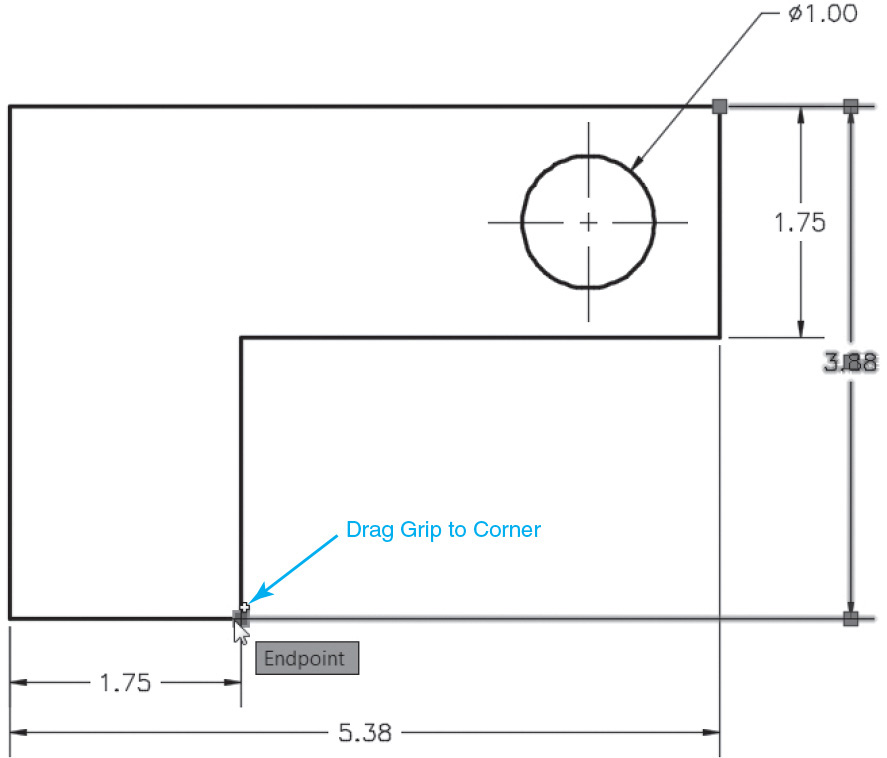
![]() Save your drawing.
Save your drawing.
Cleaning Up Layout Space
Now that we have some basic dimensions on the drawing, let’s go back to the layout space and make some adjustments to the viewport and the title block so we can get the drawing ready for plotting.
Setting the Viewport Scale
Remember that in layout space (paper space), viewports are simply holes or windows into the model space environment. You can activate a viewport to zoom and pan around model space and even make changes to your model. You can also assign a viewport scale to each viewport. By setting the viewport scale, you are telling AutoCAD to display the model at a certain scale factor (full-scale, half-scale, 1/8″ = 1′-0″, etc.) within that viewport. The viewport in the ANSI A Title Block layout was part of the template file used to create the drawing. In the next exercise, you’ll set the scale of the viewport and adjust the position of the model within the title border.
Exercise 2-24 Setting the Viewport Scale
![]() Choose the ANSI A Title Block tab at the bottom of the drawing to switch to layout space. The geometry from model space will show up in the viewport.
Choose the ANSI A Title Block tab at the bottom of the drawing to switch to layout space. The geometry from model space will show up in the viewport.
![]() Choose the Zoom All tool from the Zoom tools on the navigation bar. This will fill the drawing area with your layout sheet.
Choose the Zoom All tool from the Zoom tools on the navigation bar. This will fill the drawing area with your layout sheet.
![]() Double-click inside the viewport to activate it. The viewport will highlight, and the crosshairs will appear only inside the viewport.
Double-click inside the viewport to activate it. The viewport will highlight, and the crosshairs will appear only inside the viewport.
![]() Click on the Automatically Add Scales icon right to the left of the Viewport Scale button on the status bar shown in Figure 2-51, and turn it on so that the dimensions automatically scale in the next step.
Click on the Automatically Add Scales icon right to the left of the Viewport Scale button on the status bar shown in Figure 2-51, and turn it on so that the dimensions automatically scale in the next step.
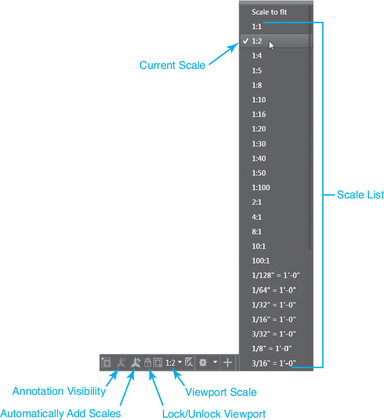
![]() Click on the down arrow to the right of the Viewport Scale button on the status bar shown in Figure 2-51 to display the scale list and choose 1:2. Your drawing will zoom so that your model is half-scale (1:2) on your layout (paper).
Click on the down arrow to the right of the Viewport Scale button on the status bar shown in Figure 2-51 to display the scale list and choose 1:2. Your drawing will zoom so that your model is half-scale (1:2) on your layout (paper).
![]() Choose Pan from the navigation bar, and pan your drawing so that it looks like Figure 2-52.
Choose Pan from the navigation bar, and pan your drawing so that it looks like Figure 2-52.
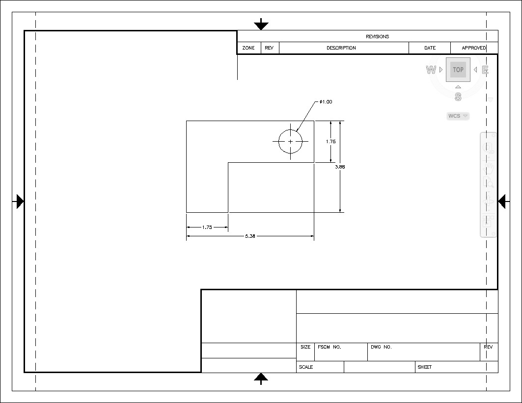
![]() Save your drawing.
Save your drawing.
Notice that the dimension features are now twice as large as they were before you set the viewport scale. This is because the dimension style was set up earlier with the Annotative feature turned on (see Figure 2-35). When combined with turning on the feature that automatically scales annotative objects, as done in step 4 of Exercise 2-24, this setting actually creates another set of dimensions for the new viewport/annotation scale so that you can view your drawing at different scales and have all the annotation objects display at the correct size.
Tip
It is possible to display all of an annotation object’s scale representations when you select it so that each size is visible. You can grip edit the current scale’s representation without affecting any of the other scale representations. For instance, by using grips, you can relocate one scale representation while leaving the others in their current locations, as shown in Figure 2-53.
Exercise 2-25 Adjusting Dimensions
![]() Change the viewport scale back to 1:1 on the status bar. The view is zoomed in at a scale of 1:1, and the dimension features are scaled down by half.
Change the viewport scale back to 1:1 on the status bar. The view is zoomed in at a scale of 1:1, and the dimension features are scaled down by half.
![]() Choose the Undo tool to set the scale back to 1:2.
Choose the Undo tool to set the scale back to 1:2.
![]() Click on the Annotation Visibility icon to the left of the Viewport Scale button on the status bar shown in Figure 2-51. Turn it on so that all scale representations of an annotation object are shown when it is selected and grips are turned on.
Click on the Annotation Visibility icon to the left of the Viewport Scale button on the status bar shown in Figure 2-51. Turn it on so that all scale representations of an annotation object are shown when it is selected and grips are turned on.
![]() Use grips to relocate the dimensions so that they no longer overlap, as shown in Figure 2-53.
Use grips to relocate the dimensions so that they no longer overlap, as shown in Figure 2-53.
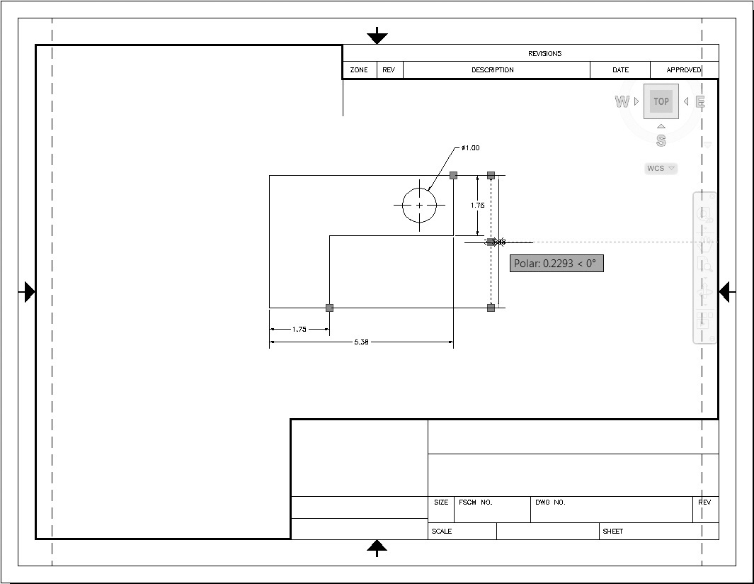
![]() Double-click outside the viewport to close the viewport and switch to paper space.
Double-click outside the viewport to close the viewport and switch to paper space.
![]() Save your drawing.
Save your drawing.
Text
Now, let’s update the title block and place some text. When placing text in a drawing, AutoCAD will ask you to define a box in which to place the text. Once that text box is defined, a miniature text editor appears where you specified, and you can start typing your text. The text editor has a number of formatting features found in many text editors (fonts, bold, justification, etc.). You can insert predefined text fields (such as the file name, date, plot scale, etc.) and can also import text from an external text file.
![]() Make sure that you are still in paper space and that the viewport is not active.
Make sure that you are still in paper space and that the viewport is not active.
![]() Set the Title Block layer current by selecting it from the Layer drop-down list.
Set the Title Block layer current by selecting it from the Layer drop-down list.
![]() Choose Zoom Window from the navigation bar, and zoom up on the lower right corner of the title block, as shown in Figure 2-54.
Choose Zoom Window from the navigation bar, and zoom up on the lower right corner of the title block, as shown in Figure 2-54.
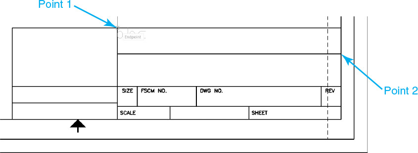
![]() Choose the Multiline Text tool from the Annotation panel on the Home tab of the ribbon. AutoCAD prompts you to Specify first corner:.
Choose the Multiline Text tool from the Annotation panel on the Home tab of the ribbon. AutoCAD prompts you to Specify first corner:.
![]() Pick the endpoints at point 1 and point 2 shown in Figure 2-54. The Text Editor context tab of the ribbon replaces the Home tab of the ribbon at the top of the screen, and a flashing text cursor is displayed at the upper left corner of the text box. This indicates where the text will appear when you type.
Pick the endpoints at point 1 and point 2 shown in Figure 2-54. The Text Editor context tab of the ribbon replaces the Home tab of the ribbon at the top of the screen, and a flashing text cursor is displayed at the upper left corner of the text box. This indicates where the text will appear when you type.
![]() In the Style panel, first set the current text style to Roman, then set the text height to .125.
In the Style panel, first set the current text style to Roman, then set the text height to .125.
![]() Choose the Justification button on the Paragraph panel and choose Middle Center MC from the menu. The flashing cursor will move to the middle of the text box.
Choose the Justification button on the Paragraph panel and choose Middle Center MC from the menu. The flashing cursor will move to the middle of the text box.
![]() In the text box, type Introduction to AutoCAD and choose Close Text Editor from the Close panel. AutoCAD places the text centered in the text box you specified.
In the text box, type Introduction to AutoCAD and choose Close Text Editor from the Close panel. AutoCAD places the text centered in the text box you specified.
![]() Press <Enter> to repeat the MTEXT command.
Press <Enter> to repeat the MTEXT command.
![]() Pick the endpoints at point 1 and point 2 shown in Figure 2-55. The Text Editor context tab of the ribbon replaces the Home tab of the ribbon at the top of the screen, and a flashing text cursor is displayed at the upper left corner of the text box.
Pick the endpoints at point 1 and point 2 shown in Figure 2-55. The Text Editor context tab of the ribbon replaces the Home tab of the ribbon at the top of the screen, and a flashing text cursor is displayed at the upper left corner of the text box.
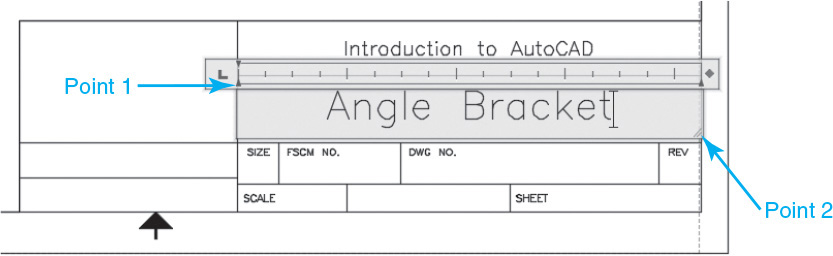
![]() Set the style to Roman again, then set the text height to .250 and choose Middle Center MC from the Justification menu.
Set the style to Roman again, then set the text height to .250 and choose Middle Center MC from the Justification menu.
![]() Type Angle Bracket in the text box and then choose Close Text Editor to end the command.
Type Angle Bracket in the text box and then choose Close Text Editor to end the command.
![]() Save your drawing.
Save your drawing.
So far, you’ve simply typed in the text you want to display. You may want to place text that is specific to the drawing (such as the drawing file name) or that is dynamic (for example, the plot time or date the drawing was last revised). AutoCAD provides you with a number of predefined text fields that will display various drawing or system information. In the following exercise, you’ll use a text field to create the text.
Exercise 2-27 Using a Text Field
![]() Choose the Multiline Text tool from the Annotation panel on the Home tab of the ribbon, and select the endpoints at point 1 and point 2 shown in Figure 2-56. The Text Editor context tab of the ribbon replaces the Home tab of the ribbon at the top of the screen, and a flashing text cursor is displayed at the upper left corner of the text box.
Choose the Multiline Text tool from the Annotation panel on the Home tab of the ribbon, and select the endpoints at point 1 and point 2 shown in Figure 2-56. The Text Editor context tab of the ribbon replaces the Home tab of the ribbon at the top of the screen, and a flashing text cursor is displayed at the upper left corner of the text box.
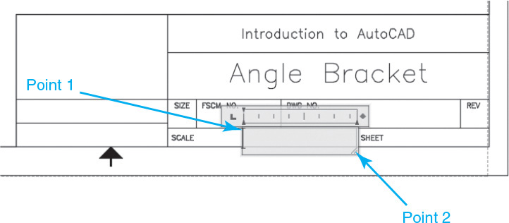
![]() Set the style to Roman, then set the text height to .125 and the justification to Middle Center MC.
Set the style to Roman, then set the text height to .125 and the justification to Middle Center MC.
![]() Choose Field from the Insert panel. This displays the Field dialog box (see Figure 2-57).
Choose Field from the Insert panel. This displays the Field dialog box (see Figure 2-57).
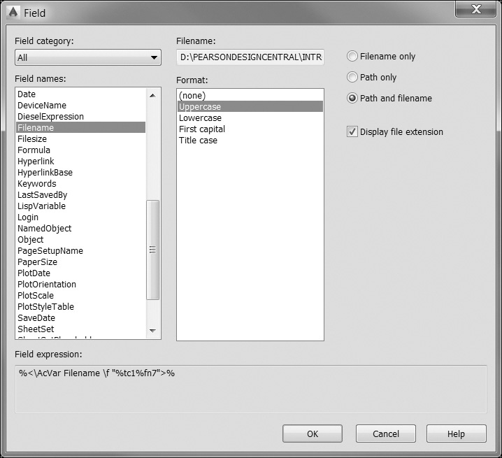
![]() From the Field names: list, choose Filename.
From the Field names: list, choose Filename.
![]() In the Format: area, choose Uppercase.
In the Format: area, choose Uppercase.
![]() Select the Filename only option and uncheck the box on the Display file extension setting (see Figure 2-57).
Select the Filename only option and uncheck the box on the Display file extension setting (see Figure 2-57).
![]() Choose OK to insert the field into the drawing. The Field dialog box will close.
Choose OK to insert the field into the drawing. The Field dialog box will close.
![]() Choose Close Text Editor to end the command. The drawing file name CH2_EXERCISE appears in the title block (see Figure 2-58). The field text is highlighted to indicate that it is a field value.
Choose Close Text Editor to end the command. The drawing file name CH2_EXERCISE appears in the title block (see Figure 2-58). The field text is highlighted to indicate that it is a field value.
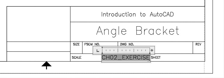
![]() Choose Zoom Extents from the navigation bar.
Choose Zoom Extents from the navigation bar.
![]() Save your drawing.
Save your drawing.
As you can see from the Field dialog box (see Figure 2-57), there are a number of predefined fields. Using field names is a great time-saver. By default, the field is updated every time you regenerate, save, or plot your drawing. So, any changes to the drawing file name will automatically update the text.
Plotting and Page Setups
When you plot a drawing, AutoCAD needs to know a number of different settings (printer, paper size, orientation, margins, color settings, plot scale, etc.). You can specify these settings each time you plot, but for consistency, AutoCAD allows you to save all these settings to a page setup. A page setup is simply a group of plot settings saved to a user-specified name. In the following exercise, you will make changes to the page setup associated with the ANSI A Title Block layout.
page setup: A collection of plot settings that are applied to a drawing layout.
![]() Select the Output tab of the ribbon to display the plotting tools and options.
Select the Output tab of the ribbon to display the plotting tools and options.
![]() Choose Page Setup Manager from the Plot panel. This displays the Page Setup Manager dialog box shown in Figure 2-59.
Choose Page Setup Manager from the Plot panel. This displays the Page Setup Manager dialog box shown in Figure 2-59.
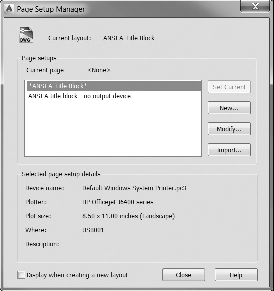
![]() Choose New... to display the New Page Setup dialog box (see Figure 2-60).
Choose New... to display the New Page Setup dialog box (see Figure 2-60).
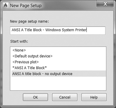
![]() Enter ANSI A Title Block—Windows System Printer as the new page setup name and choose OK. This displays the Page Setup dialog box (see Figure 2-61).
Enter ANSI A Title Block—Windows System Printer as the new page setup name and choose OK. This displays the Page Setup dialog box (see Figure 2-61).
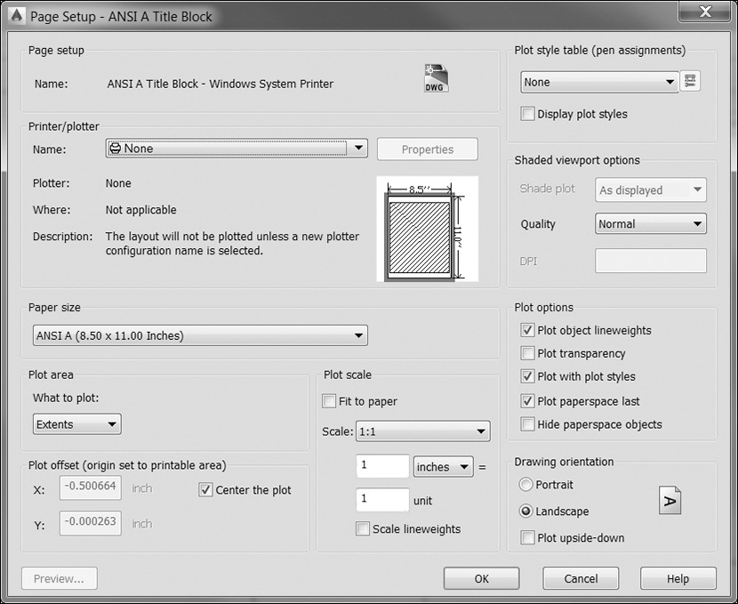
![]() From the Printer/plotter list, select Default Windows System Printer.pc3. This is your default Windows printer.
From the Printer/plotter list, select Default Windows System Printer.pc3. This is your default Windows printer.
![]() From the Paper size list, choose Letter.
From the Paper size list, choose Letter.
![]() Choose Extents from the What to plot: list. This tells AutoCAD to plot everything currently shown in the drawing.
Choose Extents from the What to plot: list. This tells AutoCAD to plot everything currently shown in the drawing.
![]() Check the Center the plot option in the Plot offset area.
Check the Center the plot option in the Plot offset area.
![]() If checked, clear the check from the Fit to paper box.
If checked, clear the check from the Fit to paper box.
![]() Choose 1:1 from the Scale drop-down list.
Choose 1:1 from the Scale drop-down list.
![]() Choose Landscape in the Drawing orientation area. Your selections should be the same as those shown in Figure 2-61.
Choose Landscape in the Drawing orientation area. Your selections should be the same as those shown in Figure 2-61.
![]() Choose Preview... to see how your drawing will look when it is printed. AutoCAD will switch to a print preview view. The buttons at the top of the print preview window allow you to pan and zoom around the preview.
Choose Preview... to see how your drawing will look when it is printed. AutoCAD will switch to a print preview view. The buttons at the top of the print preview window allow you to pan and zoom around the preview.
![]() Choose the Close button to close the preview window.
Choose the Close button to close the preview window.
![]() Choose OK to save the page setup. The Page Setup Manager dialog box returns with the new page setup listed.
Choose OK to save the page setup. The Page Setup Manager dialog box returns with the new page setup listed.
![]() Select the page setup you just created and then choose Set Current. This applies the page setup settings to the current layout.
Select the page setup you just created and then choose Set Current. This applies the page setup settings to the current layout.
![]() Choose Close to close the Page Setup Manager dialog box.
Choose Close to close the Page Setup Manager dialog box.
![]() Save your drawing.
Save your drawing.
Tip
In order for the centerline dashes and gaps to show up correctly, you must set the value of the PSLTSCALE system variable to 0. The PSLTSCALE variable controls whether or not linetypes are scaled automatically by the viewport scale when working in paper space. See page 600 in Chapter 14 for details.
Note
Many times a page setup has the same name as the layout space; however, they are not the same thing. Be careful not to confuse the page setup with the drawing layout. The layout is a drawing space where your drawing objects (title blocks, viewports, etc.) reside. The page setup is a collection of plot settings that are applied to the layout when you plot the drawing.
Notice the dashed line that appears around the edge of the layout (see Figure 2-62). This dashed line represents the printable area on your drawing. It’s not an actual drawing object (you can’t select it), but only a visual indication of what part of your drawing will be printed. If any part of your drawing extends outside this dashed line, those parts will be clipped from the final print. To fix this, you can adjust the plot scale of your drawing, move or adjust the geometry within your drawing, or adjust the margins of your printer.
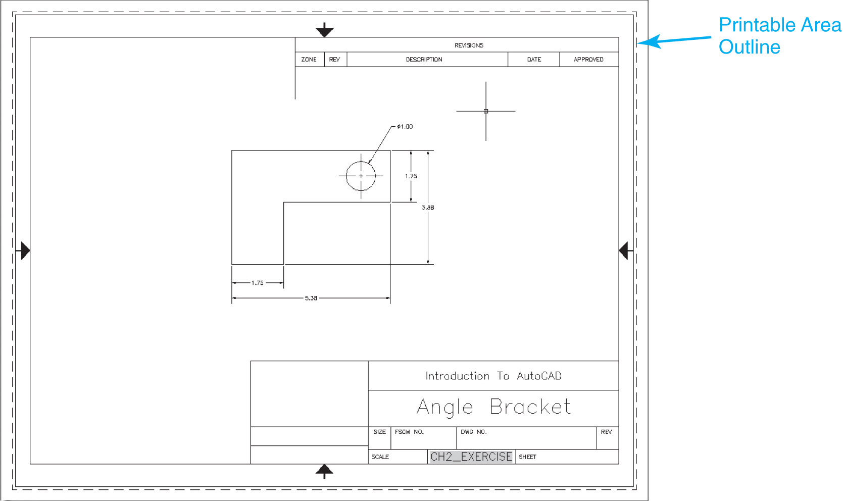
Plotting
When you plot a drawing in AutoCAD, you are presented with the Plot dialog box (see Figure 2-63). The Plot dialog box has all the same settings as the Page Setup dialog box (in fact, you can use the PLOT command to create page setups). These options allow you to make last-minute changes to your page setup or temporarily override settings contained in the page setup. For example, your page setup may be defined for a C- or D-size plot, but you may want to create a quick check plot on an A-size sheet. The PLOT command allows you to change your plot setting without going through the process of creating a new page setup.
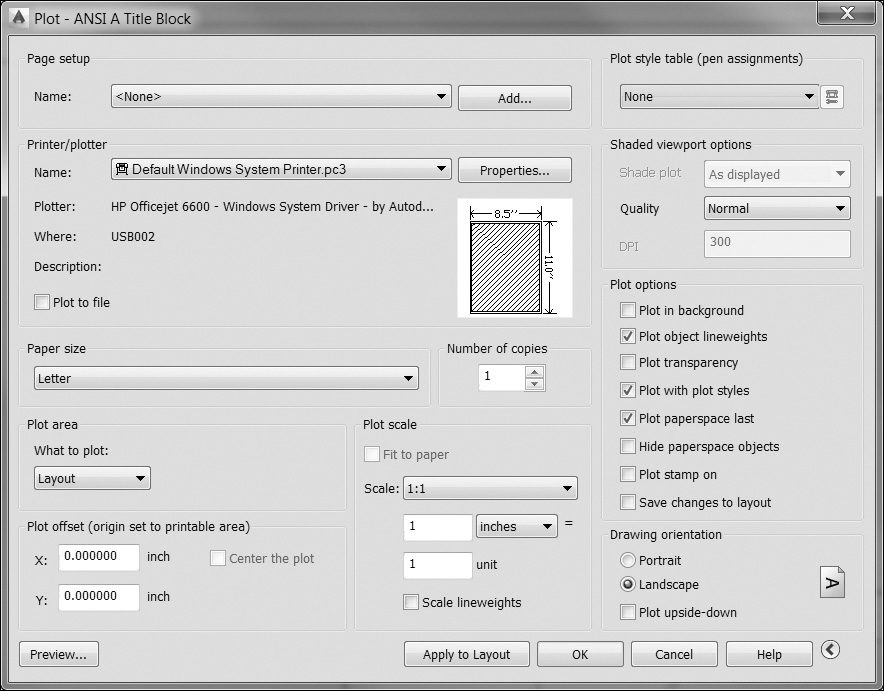
In the following exercise, you’ll create a plot using the page setup you just created.
Note
In the following exercise, your printer features and settings may differ from those shown here.
![]() Choose the Plot tool from the Plot panel. The Plot dialog box appears (see Figure 2-63). If your dialog box looks different, choose the arrow next to the Help button at the bottom to expand the dialog box and see all options.
Choose the Plot tool from the Plot panel. The Plot dialog box appears (see Figure 2-63). If your dialog box looks different, choose the arrow next to the Help button at the bottom to expand the dialog box and see all options.
![]() From the Page setup list, choose ANSI A Title Block—Windows System Printer.
From the Page setup list, choose ANSI A Title Block—Windows System Printer.
![]() Verify that all the settings are correct and choose Preview.... The plot preview displays.
Verify that all the settings are correct and choose Preview.... The plot preview displays.
![]() Choose the Plot button to plot your drawing to your default Windows system printer. A plot progress bar will appear briefly, and AutoCAD will return to the command prompt when the plot is complete.
Choose the Plot button to plot your drawing to your default Windows system printer. A plot progress bar will appear briefly, and AutoCAD will return to the command prompt when the plot is complete.
![]() Save your drawing.
Save your drawing.
Once the plot is complete, AutoCAD will display a balloon in the notification tray in the lower right corner of the status bar (see Figure 2-64). This indicates the results of the PLOT command and reports any errors that may have occurred. To view the plot results, click on the indicated link to display the Plot and Publish Details box. Here you can view the results of all plots submitted during the current AutoCAD session.

Chapter Summary
You have now walked through a typical AutoCAD drawing session. In this chapter we have gone through the steps to quickly create a new drawing based on an existing AutoCAD template drawing that already has a title block and border established. We saw that templates help us to be more productive by saving the time it would normally take to create a border each time we start a new drawing, as well as help promote CAD standards by having everything preestablished.
We then created a simple drawing using AutoCAD’s precision drawing tools and then modified it using different AutoCAD modify commands and techniques, including grips. Then, after most of the line work was complete, we annotated the drawing by adding associated dimensions that automatically update when the drawing is modified and created title block text that included a field to automatically insert the drawing name.
In the final steps, we set the drawing up to plot on an 8-1/2 × 11 (ANSI A) size paper by setting the drawing scale to 1:2 using the predefined Viewport Scale list on the right side of the status bar. Because we took advantage of AutoCAD’s automated Annotation Scale feature, we then had to adjust the location of the dimensions that were automatically scaled up. After everything was nice and tidy, we plotted the drawing using the default Windows system printer.
Chapter Test Questions
Multiple Choice
Circle the correct answer.
1. Model space is:
a. Only for three-dimensional objects
b. Limited in size so you must scale your model appropriately
c. Generally used to draw objects that exist in the real world
d. Generally used to draw objects that exist only on paper
2. In the following command line prompt, what would you type to use the Ttr option?
Specify center point for circle or [3P 2P Ttr (tan tan radius)]:
a. 3P<Enter>
b. (tan tan radius)<Enter>
c. 2P<Enter>
d. T<Enter>
3. Which of the following settings does not allow you to control point specifications?
a. Grid
b. Snap
c. Ortho
d. Polar
4. The command line:
a. Cannot be moved
b. Can be turned off
c. Is the only way to communicate with AutoCAD
d. Cannot be docked
5. Scrolling the wheel of a wheel mouse will:
a. Scroll the text in the command line
b. Do nothing
c. Pan the drawing up and down
d. Zoom the drawing in and out
6. Which of the following is not a property common to all objects?
a. Length
b. Layer
c. Color
d. Lineweight
7. Dimensions:
a. Can be placed only in model space
b. Can be placed only in paper space
c. Must be erased and redrawn if the model changes
d. Are controlled by their associated dimension style
8. Grips appear:
a. At key points on drawing objects
b. On a separate layer
c. Every time you click on the screen
d. Only in model space
9. A page setup:
a. Is the same thing as a paper space layout
b. Can be defined only in a drawing template
c. Is a collection of plot settings
d. Must have the same name as a paper space layout
10. The dashed line that appears around the edge of a layout:
a. Can be erased if needed
b. Is on its own layer and can be turned off if desired
c. Shows a visual indication of the area that will be printed
d. Shows up on the printed drawing
Matching
Write the number of the correct answer on the line.
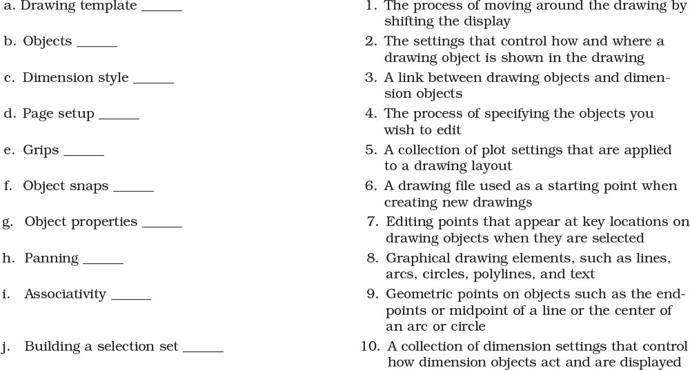
1. True or False: There is only one layout allowed in a drawing file.
2. True or False: A layout can have only one viewport.
3. True or False: There is only one model space allowed in a drawing file.
4. True or False: Polar tracking can be set to detect any angle.
5. True or False: You can only use the REDO command immediately after using the UNDO command.
6. True or False: Objects on a layer that is frozen can be seen but not modified.
7. True or False: Objects on a layer that is turned off can still be modified.
8. True or False: To move an object, you must always select the object first and then start the MOVE command.
9. True or False: You can override page setup settings when you plot.
10. True or False: Dimensions can update to follow changes to your geometry.