
Chapter 5. Drawing Tools and Drafting Settings
• Use the Grid Mode and Snap Mode drawing tools to locate points quickly and precisely
• Draw orthogonally using the Ortho Mode drawing tool
• Draw at angles using the Polar Tracking drawing tool
• Use basic object snaps to locate points precisely relative to existing objects
• Defer object snaps to locate complex points
• Use advanced object snaps to locate points using acquired points and alignment paths
• Locate points relative to multiple objects by using the Object Snap Tracking feature to display multiple intersecting alignment path tracking vectors
• Control dynamic input settings
• Use construction lines to increase productivity and precision when creating multiple-view drawings
Introduction
Recall from Chapter 1 that two of the most important benefits of using CAD to create technical drawings are increased productivity and improved precision.
These benefits are achieved in AutoCAD primarily through the use of the drawing tools and drafting settings explained in this chapter.
Drawing tools are toggles that can be turned on and off as needed by clicking on the appropriate status bar buttons located at the bottom of the AutoCAD display window shown in Figure 5-1.

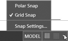
Additional button-specific menu items are also included on each button’s arrow menu located on the right so that you can quickly access the selected drawing tool’s settings and features. The shortcut menu for the Grid Mode and Snap Mode tools is shown in Figure 5-2.
Drawing tools can also be turned on and off using the function keys at the top of your keyboard, or they can be typed in at the AutoCAD command line. Each method is listed with the corresponding drawing tool throughout this chapter.
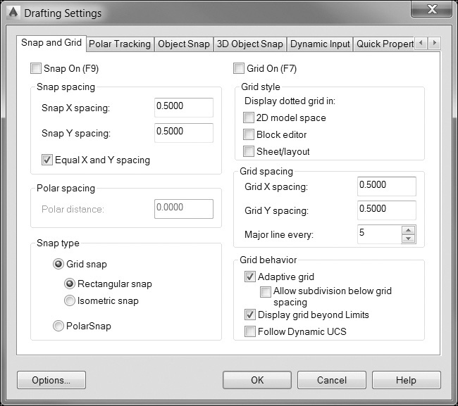
Most of the drawing tools work in conjunction with different drafting settings. For instance, the Grid Mode button turns a grid display on and off, whereas the grid spacing (X and Y distance between grid lines) is controlled via the drafting settings. The grid spacing and other drafting settings are managed using the Drafting Settings dialog box shown in Figure 5-3.
Drafting Settings |
|
Menu: |
Tools Drafting Settings... |
Command Line: |
DSETTINGS |
Command Alias: |
DS or SE |
Note
Any of the drawing tool buttons discussed in this chapter can be removed from the status bar via the status bar Customization menu. To display the Customization menu, click on the Customization menu icon at the far right of the status bar.
For More Details
See the section “Keyboard Commands” on page 46 in Chapter 1 for a complete list of function keys. See the “Status Bar” section on page 36 in Chapter 1 for more information about turning status bar features on and off.
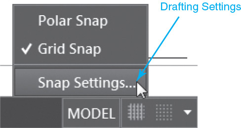
The Drafting Settings dialog box can be displayed by selecting Drafting Settings... from the Tools menu or typing DSETTINGS. Even easier, you can click the down arrow on many of the drawing tool buttons on the status bar to display a shortcut menu similar to the one shown in Figure 5-4 and select its corresponding Settings... menu item.
Tip
All the drawing tools and drafting settings can be accessed when a command is active. This means that you can turn drawing tools on or off or change your drafting settings in the middle of most commands on an as-needed basis.
Grid Mode
The grid display is a rectangular pattern of evenly spaced lines you can turn on in your drawing to help you visually locate points. It is similar to using a sheet of graph paper when drawing with pencil and paper, except that you can control the distance between the lines and can change them at any time using the Drafting Settings dialog box. The grid display does not plot and is provided strictly as a visual aid. The grid display does not affect the cursor movement—this feature is controlled by the Snap mode explained in the next section.
Grid Mode |
|
Status Bar: |
|
Function Key: |
F7 |
Command Line: |
GRID |
Keyboard Combo: |
Ctrl+G |
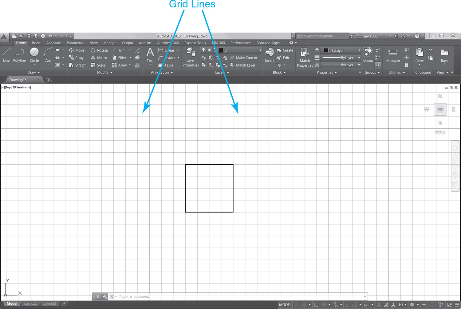
Figure 5-5 shows a drawing with the grid display turned on with the default spacing of 0.50″ between the lines in both the horizontal and vertical axes.
Setting the Grid Style
It is possible to set the grid display back to the old dot-style display on the Snap and Grid tab of the Drafting Settings dialog box shown in Figure 5-6. In fact, you can control it at different levels: 2D model space, the Block Editor, and in paper space layouts.
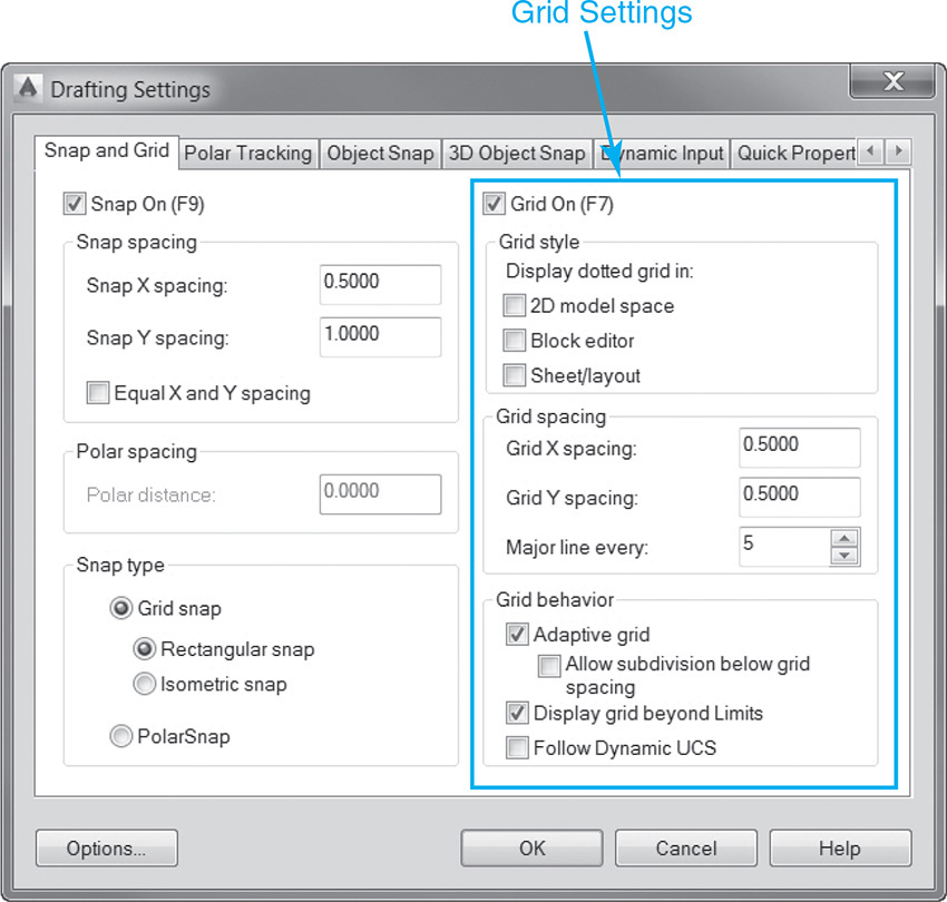
Setting the Grid Spacing
The horizontal and vertical spacing between the grid lines is controlled on the Snap and Grid tab of the Drafting Settings dialog box shown in Figure 5-6. You can change the distance between the lines by specifying the Grid X spacing for the horizontal distance and the Grid Y spacing for the vertical distance. The X and Y distances are typically set to an equal value. In fact, when you try to change one distance, the other distance is updated automatically.
The Major line every: setting specifies the frequency of major grid lines compared to minor grid lines.
Controlling Grid Mode Behavior
The settings in the Grid behavior section of the Drafting Settings dialog box are primarily used to control the appearance of the grid lines that are displayed when the current visual style is set to any visual style except 2D Wireframe.
The Adaptive grid setting limits the density of the grid when the drawing is zoomed out using the Major line every: setting introduced earlier to turn minor grid lines off.
The Allow subdivision below grid spacing setting generates additional, more closely spaced grid lines when zoomed in. The spacing and frequency of these minor grid lines is determined by the frequency of the major grid lines.
The Display grid beyond Limits setting allows you to display the grid beyond the area specified by the LIMITS command.
The Follow Dynamic UCS setting is a 3D tool that allows you to automatically update the grid plane to follow the XY plane of the dynamic UCS.
Snap Mode
The Snap Mode drawing tool controls the movement of your cursor so that you can select points in your drawing only at specific X and Y increments. It is typically used in conjunction with the grid display explained in the previous section. The grid display provides the visual reference, whereas the Snap mode forces your pick points to be located precisely at specific coordinate locations.
Snap Mode |
|
Status Bar: |
|
Function Key: |
F9 |
Command Line: |
SNAP |
Keyboard Combo: |
Ctrl+B |
By default, the X and Y spacing for both tools are set the same so that your cursor “snaps” directly to the grid display lines when both drawing tools are turned on at the same time. It is possible to set the X and Y spacing for grid and snap to different values, although it is recommended that they relate to each other to avoid confusion.
Tip
When Snap Mode is on, your cursor will not snap to grid points when selecting objects—only when specifying points. Snap Mode is temporarily turned off during the selection process so that it is easier to select objects.
Setting the Snap Spacing
The horizontal and vertical spacing between the snap points is controlled on the Snap and Grid tab of the Drafting Settings dialog box shown in Figure 5-7. You can change the distance between the snap points by specifying the Snap X spacing for the horizontal distance and the Snap Y spacing for the vertical distance. The X and Y distances are typically set to an equal value. By default, when you try to change one distance the other distance is updated automatically. You must uncheck the Equal X and Y spacing check box shown in Figure 5-7 before setting values that are not the same.
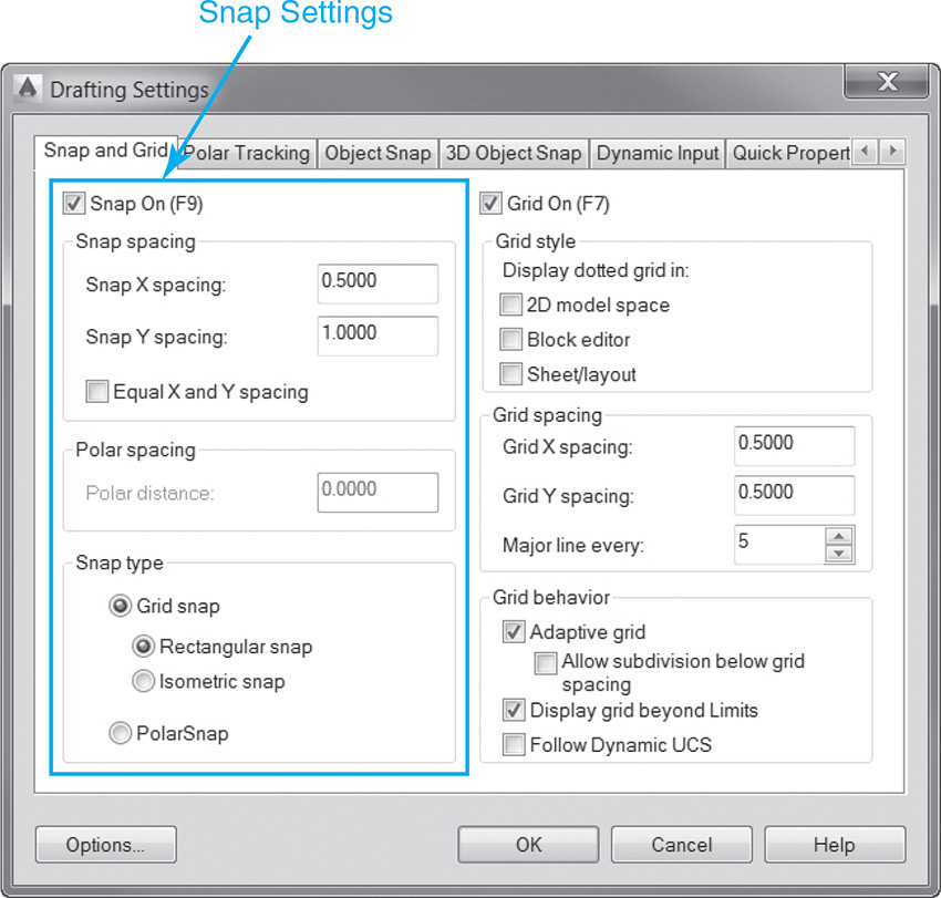
As mentioned, it is possible to set the snap X and Y spacing to different values than the grid X and Y spacing, but it is suggested that one is an increment of the other. For instance, you might set the snap X and Y spacing to 0.25″, while the grid X and Y spacing remains at 0.50″. With these settings, your cursor will still snap to each grid and halfway between each grid line.
Setting the Snap Type and Style
There are two major types of Snap modes: Grid snap and Polar snap. You can switch between the different types using the option buttons in the Snap type section of the Drafting Settings dialog box shown in Figure 5-7. The default mode is Grid snap, which has two different styles:
• Rectangular snap (default) Traditional orthogonal snap pattern with rows and columns of snap points at the specified X and Y spacing
• Isometric snap Angled snap pattern where snap points are aligned at 30°, 90°, and 150° angles at the specified spacing so you can create isometric drawings
Polar snap mode is used with the Polar Tracking drawing tool so that you can snap to points along polar tracking vectors at the specified spacing. Polar tracking and the Polar snap mode are explained later in this chapter.
Exercise 5-1 Creating a Drawing Using Snap Mode and Grid Mode
![]() Start a new drawing using the acad.dwt drawing template.
Start a new drawing using the acad.dwt drawing template.
![]() Turn off all the drawing tool buttons on the status bar.
Turn off all the drawing tool buttons on the status bar.
![]() Turn on the Grid Mode button on the status bar.
Turn on the Grid Mode button on the status bar.
![]() Select the Zoom Extents tool to zoom to the limits of the drawing. You should now be able to see the whole grid on the drawing display.
Select the Zoom Extents tool to zoom to the limits of the drawing. You should now be able to see the whole grid on the drawing display.
![]() Start the LINE command.
Start the LINE command.
![]() Draw a rectangle by picking points in the drawing.
Draw a rectangle by picking points in the drawing.
![]() Exit the LINE command.
Exit the LINE command.
![]() Turn on the Snap Mode button on the status bar.
Turn on the Snap Mode button on the status bar.
![]() Start the LINE command.
Start the LINE command.
![]() Draw another rectangle similar to the first by picking points in the drawing. The cursor now snaps to the grid lines on the screen.
Draw another rectangle similar to the first by picking points in the drawing. The cursor now snaps to the grid lines on the screen.
![]() Exit the LINE command.
Exit the LINE command.
![]() Click on the down arrow menu to the right of the Snap Mode button on the status bar and select Snap Settings... from the shortcut menu. The Snap and Grid tab of the Drafting Settings dialog box is displayed (see Figure 5-7).
Click on the down arrow menu to the right of the Snap Mode button on the status bar and select Snap Settings... from the shortcut menu. The Snap and Grid tab of the Drafting Settings dialog box is displayed (see Figure 5-7).
![]() Change the Snap X spacing to 0.25. The Snap Y spacing will change to match. Exit the Drafting Settings dialog box by selecting OK.
Change the Snap X spacing to 0.25. The Snap Y spacing will change to match. Exit the Drafting Settings dialog box by selecting OK.
![]() Start the LINE command.
Start the LINE command.
![]() Draw another rectangle by picking points in the drawing. The cursor now snaps both to the grid lines and to points halfway between the grid lines.
Draw another rectangle by picking points in the drawing. The cursor now snaps both to the grid lines and to points halfway between the grid lines.
![]() Exit the LINE command.
Exit the LINE command.
![]() Save your drawing as CH5_EXERCISE1.
Save your drawing as CH5_EXERCISE1.
Ortho Mode
The Ortho Mode drawing tool restricts your cursor movement to the horizontal (X-) and vertical (Y-) axes so you can quickly draw horizontal and vertical lines at right angles (90°) to each other. This right-angle approach to drafting is often referred to as drawing “orthogonally”; hence the term ortho. Drawing with Ortho Mode turned on allows you to draw rectangular objects quickly and be assured that all the angles are square.
Ortho Mode |
|
Status Bar: |
|
Function Key: |
F8 |
Command Line: |
ORTHO |
Keyboard Combo: |
Ctrl+L |
Note
The Ortho Mode and Polar Tracking drawing tools described later in this chapter cannot be on at the same time. Turning the Ortho Mode button on immediately turns the Polar Tracking button off, and vice versa.
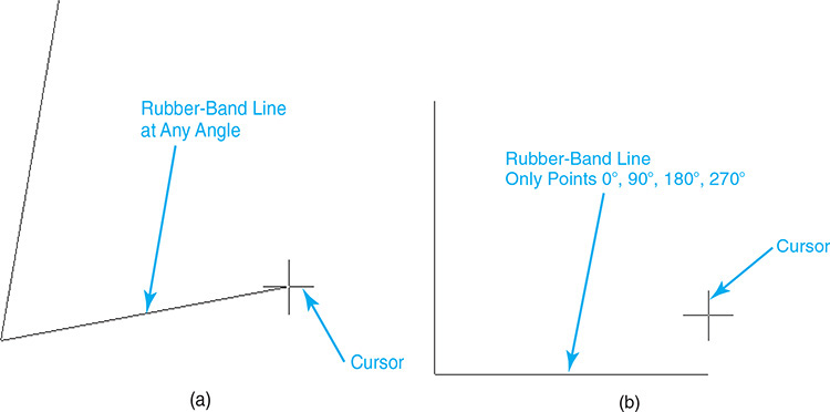
When Ortho Mode is turned off, the rubber-band line that indicates the cursor movement points at any angle you move your cursor, as shown in Figure 5-8A. When Ortho Mode is turned on, the rubber-band line that indicates the cursor direction follows the horizontal or vertical axis, depending on which axis is nearer to the cursor at the time, as shown in Figure 5-8B.
AutoCAD overrides Ortho mode when you enter coordinates at the command line or use any of the object snaps explained later in this chapter.
Exercise 5-2 Creating a Drawing Using Ortho Mode
![]() Continue from Exercise 5-1.
Continue from Exercise 5-1.
![]() UNDO or ERASE all of the line work from Exercise 5-1.
UNDO or ERASE all of the line work from Exercise 5-1.
![]() Turn off all the drawing tool buttons on the status bar.
Turn off all the drawing tool buttons on the status bar.
![]() Select the Zoom Extents tool to zoom to the limits of the drawing.
Select the Zoom Extents tool to zoom to the limits of the drawing.
![]() Turn the Ortho Mode button on.
Turn the Ortho Mode button on.
![]() Start the LINE command.
Start the LINE command.
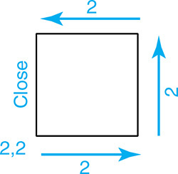
![]() Type 2,2<Enter> to specify the first point.
Type 2,2<Enter> to specify the first point.
![]() Drag the cursor to the right. The Ortho mode setting will lock the cursor movement to the 0° direction.
Drag the cursor to the right. The Ortho mode setting will lock the cursor movement to the 0° direction.
![]() Type 2<Enter>. AutoCAD draws a line 2 units to the right (angle of 0°).
Type 2<Enter>. AutoCAD draws a line 2 units to the right (angle of 0°).
![]() Drag the cursor up (90°) and type 2<Enter>. AutoCAD draws a line 2 units up (angle of 90°).
Drag the cursor up (90°) and type 2<Enter>. AutoCAD draws a line 2 units up (angle of 90°).
![]() Drag the cursor to the left (180°) and type 2<Enter>. AutoCAD draws a line 2 units to the left (angle of 180°).
Drag the cursor to the left (180°) and type 2<Enter>. AutoCAD draws a line 2 units to the left (angle of 180°).
![]() Select the Close option. AutoCAD closes the square and exits the LINE command.
Select the Close option. AutoCAD closes the square and exits the LINE command.
![]() Save your drawing. Your drawing should look like Figure 5-9.
Save your drawing. Your drawing should look like Figure 5-9.
Polar Tracking
AutoCAD provides a feature called AutoTrackingTM that helps you to draw objects at specific angles using dashed lines known as alignment paths.
AutoTracking: AutoCAD feature that helps you draw objects at specific angles or in specific relationships to other objects.
The Polar Tracking drawing tool utilizes AutoTracking so you can quickly draw and modify objects using preset polar angles. Polar tracking works by displaying a dashed alignment path and a polar tracking tooltip as you move your cursor around in a drawing that temporarily restricts your cursor movement to preset angle increments.
Polar Tracking |
|
Status Bar: |
|
Function Key: |
F10 |
Command Line: |
None |
Keyboard Combo: |
None |
By default, the increment angle is set at 90° so that an alignment path is displayed at every 90° (0°, 90°, 180°, 270°, and 360°) when the Polar Tracking button is turned on. This provides the same basic functionality of the Ortho Mode drawing tool explained earlier in the chapter. As noted earlier, when you turn the Polar Tracking button on, the Ortho Mode button gets turned off automatically, and vice versa. Both drawing tools cannot be on at the same time. Figure 5-10 shows an alignment path displayed at 0°.
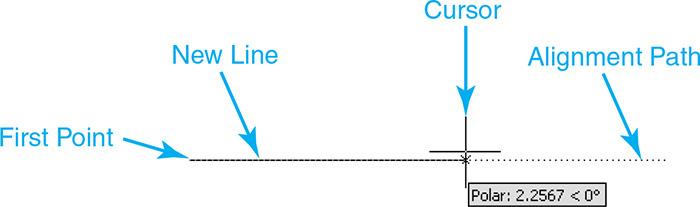
If you pick a point when an alignment path is displayed, the point is located at the distance and angle displayed in the polar tracking tooltip. Even better, it is possible to use the direct distance coordinate entry method explained in Chapter 4 to locate a point at a specified distance along an alignment path. Any time an alignment path is displayed, you can enter a distance, and AutoCAD will follow the alignment path the distance specified. For example, if you enter 2 in response to the Specify next point or [Undo]: prompt while the 0° alignment path is displayed, as shown in Figure 5-10, a horizontal line segment 2 units long is created. Combining polar tracking with direct distance coordinate entry is one of the fastest and easiest ways to locate points in your drawings.
Tip
Polar tracking is not just for drawing objects. It also works with AutoCAD’s modify tools. For example, using polar tracking, you can move objects at a specific angle and distance.
Setting the Polar Tracking Angle and Measurement Method
The polar tracking settings are controlled on the Polar Tracking tab of the Drafting Settings dialog box shown in Figure 5-11.
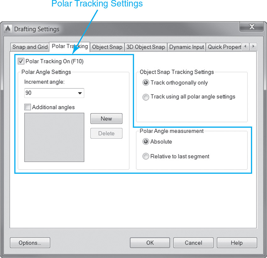
The polar tracking angle is set in the Polar Angle Settings area on the Polar Tracking tab. There are two polar angle settings:
• Increment angle A list of default preset angles ranging from 5° through 90° that controls the increment angle that polar tracking alignment paths are displayed. In Figure 5-11, a default increment angle of 45° has been selected so that a polar tracking alignment path will be displayed at every increment of 45° (0°, 45°, 90°, 135°, 180°, 225°, 270°, and 315°).
• Additional angles Additional angles that can be added using the New button. These angles are not incremental. Polar tracking alignment paths will be displayed only at each additional angle specified.
The polar tracking measurement method is set in the Polar Angle measurement area on the right side of the Polar Tracking tab. There are two Polar Angle measurement options:
• Absolute All polar tracking angles are measured from the current AutoCAD base angle setting. The default base angle setting is 0° due east or to the right.
• Relative to last segment Polar tracking angles are measured relative to the last segment, and the absolute angle is ignored.
Figures 5-12A through D show a square that is rotated at 45° being drawn with the Polar Tracking button turned on with an increment angle setting of 45° using the absolute method of angle measurement.
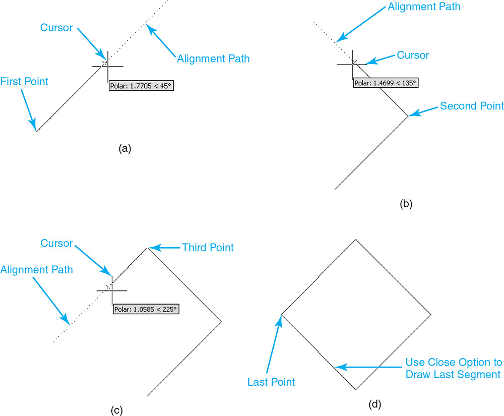
Figure 5-12 A Polar tracking alignment path at 45° B Polar tracking alignment path at 135° C Polar tracking alignment path at 225° D Completed 45° square
Tip
The AutoTrack settings are controlled via the Drafting tab of the Options dialog box. You can toggle on and off the following features: polar tracking alignment vectors, AutoTrack tooltips, and full-screen tracking vectors.
Exercise 5-3 Creating a Drawing Using Polar Tracking
![]() Continue from Exercise 5-2.
Continue from Exercise 5-2.
![]() Turn off all the drawing tool buttons on the status bar.
Turn off all the drawing tool buttons on the status bar.
![]() Click on the down arrow menu to the right of the Polar Tracking button on the status bar and select Tracking Settings... from the shortcut menu. The Polar Tracking tab of the Drafting Settings dialog box is displayed (see Figure 5-11).
Click on the down arrow menu to the right of the Polar Tracking button on the status bar and select Tracking Settings... from the shortcut menu. The Polar Tracking tab of the Drafting Settings dialog box is displayed (see Figure 5-11).
![]() Change the Increment angle list box setting to 45°. Make sure that the Polar Angle measurement setting is set to Absolute. Exit the Drafting Settings dialog box by selecting OK.
Change the Increment angle list box setting to 45°. Make sure that the Polar Angle measurement setting is set to Absolute. Exit the Drafting Settings dialog box by selecting OK.
![]() Turn the Polar Tracking button on.
Turn the Polar Tracking button on.
![]() Start the LINE command.
Start the LINE command.
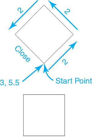
![]() Type 3,5.5<Enter> to specify the first point.
Type 3,5.5<Enter> to specify the first point.
![]() Drag the cursor up to the right until a polar tracking alignment path is displayed at 45°.
Drag the cursor up to the right until a polar tracking alignment path is displayed at 45°.
![]() Type 2<Enter> while the alignment path is displayed. AutoCAD draws a line 2 units at the angle of 45°.
Type 2<Enter> while the alignment path is displayed. AutoCAD draws a line 2 units at the angle of 45°.
![]() Drag the cursor up to the left until a polar tracking alignment path is displayed at 135°.
Drag the cursor up to the left until a polar tracking alignment path is displayed at 135°.
![]() Type 2<Enter> while the alignment path is displayed. AutoCAD draws a line 2 units at the angle of 135°.
Type 2<Enter> while the alignment path is displayed. AutoCAD draws a line 2 units at the angle of 135°.
![]() Drag the cursor down to the left until a polar tracking alignment path is displayed at 225°.
Drag the cursor down to the left until a polar tracking alignment path is displayed at 225°.
![]() Type 2<Enter> while the alignment path is displayed. AutoCAD draws a line 2 units at the angle of 225°.
Type 2<Enter> while the alignment path is displayed. AutoCAD draws a line 2 units at the angle of 225°.
![]() Select the Close option. AutoCAD closes the square and exits the command.
Select the Close option. AutoCAD closes the square and exits the command.
![]() Save your drawing. Your drawing should look like Figure 5-13.
Save your drawing. Your drawing should look like Figure 5-13.
Object Snaps
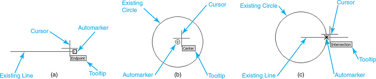
Object snaps, or osnaps as they are sometimes called, are among the most essential features available in AutoCAD. Object snaps allow your cursor to snap to exact locations relative to existing objects in your drawing so that you can locate points precisely when you are drawing or editing. Using object snaps, you can snap to the endpoint of a line (Figure 5-14A); the center point of a circle (Figure 5-14B); or if a line and circle overlap, their point of intersection (Figure 5-14C), just to name a few. There are more than 15 different types of object snaps ranging from the basic to the advanced.
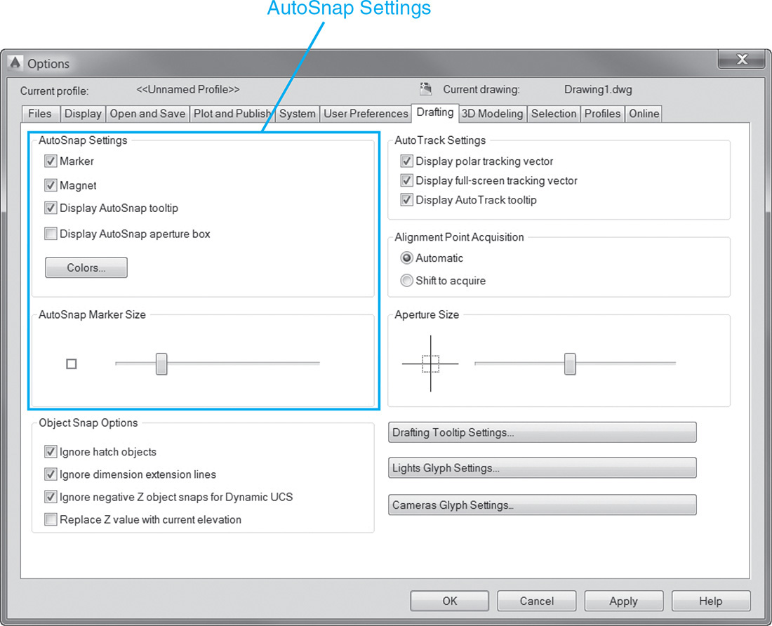
To help you use object snaps most effectively, a visual aid called AutoSnap is provided. AutoSnap provides the following features, most of which are on by default:
• Marker Displays the object snap type and location when the cursor moves over or near an object
• Magnet Feature that attracts and locks the cursor onto the object snap point when your cursor gets near an AutoSnap marker
• Tooltip Text description of the type of object snap you are snapping to in a small box at the cursor location
• Aperture box Boxed area that defines how close you need to be to an object to snap to an object snap point. The aperture box can be resized and turned on or off
All these settings, and a few others explained later, can be controlled on the Drafting tab of the Options dialog box shown in Figure 5-15.
Tip
Object snaps work only when you are prompted for a point. If you try to use an object snap alone when no command is active, the error message Unknown command is displayed.
Object Snap Modes
There are two different ways you can utilize object snaps:
• They can be used individually in response to each prompt for point coordinate information.
• You can turn on one or more object snaps on the Object Snap tab of the Drafting Settings dialog box so that they are automatically active each time you are prompted to select a point.
Entering an object snap individually in response to a request for point information makes the object snap active for only one cursor pick point. Each time AutoCAD prompts for a point you must respond with another object snap. There are a couple of ways to enter an object snap using this approach:
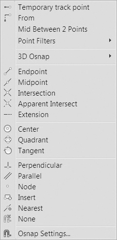
• Select the object snap from the Object Snap right-click shortcut menu (see Figure 5-16). The Object Snap shortcut menu is displayed by holding down the <Shift> key on your keyboard while right-clicking with your mouse.
• Type the desired object snap at the command line in response to a point request. The following is an example of activating the Endpoint object snap by typing end at the command line in response to a prompt for a point:
Specify first point: end
Most object snaps can be specified by entering the first three or four characters of the object snap name. In fact, if you observe the command line while selecting an object snap using the right-click shortcut menu, you can glean what is being entered at the command line so you can type it in the next time.
The second approach to using object snaps is to turn on a select number of object snaps via the Object Snap tab of the Drafting Settings dialog box (see Figure 5-17) so that they are automatically activated each time you are prompted for a point location.
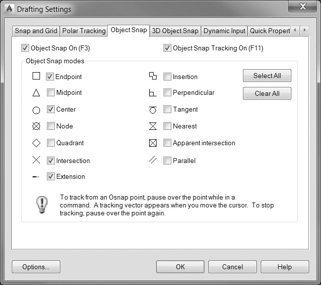
This technique is typically referred to as setting running object snaps because the selected object snaps are always running in the background as you draw.
When your cursor gets close to any running object snap feature when you are selecting points in your drawing, an AutoSnap marker is automatically displayed so you can quickly snap to the corresponding feature.
Tip
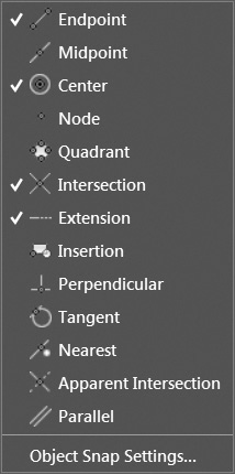
You can also set running object snaps by clicking on the down arrow menu to the right of the Object Snap button and selecting the desired object snap from the shortcut menu shown in Figure 5-18.
Using running object snaps is typically considered the most efficient approach because it allows you to quickly locate objects precisely in your drawing without having to activate an object snap each time you need it. If you do need a particular object snap that is not currently active, you can always fall back on one of the individual object snap selection approaches explained earlier:
• Use the <Shift> key and the right-click shortcut menu.
• Type the object snap name at the command line.
When you activate an individual object snap this way, it is considered an override because you are temporarily suppressing any active running object snaps for a single point selection using the currently selected object snap. After a point is selected, all the running object snaps are active again until another object snap override is selected or object snaps are turned off using the Object Snap button on the status bar.
Sometimes when using running object snaps, you might need to select a point in your drawing without using any of the active running object snaps. The easiest thing to do is to disable running object snaps by turning off the Object Snap button on the status bar. It is also possible to activate the None object snap using one of the individual override methods. The None object snap turns object snaps off temporarily.
Tip
As you will discover in this chapter, there are many different object snaps that provide a wide array of features and functionality. You will want to be judicious as you start exploring and turning on different running object snaps. You definitely don’t want to turn them all on at the same time. This will create confusion as you try to select points in your drawing. Select a few you use most often as running object snaps and then select others on an as-needed basis using the override approach.
Basic Object Snaps
The following object snaps are basic in nature and require minimal user interaction. Most involve a single point selection near the feature you want to snap to—end of a line, center of a circle, intersecting objects, and so on. Some of the object snaps in this section provide an additional feature, known as a deferred point.
deferred point: Object snap feature that allows you to “build” the object snap point using multiple point selection input by deferring the first point selected.
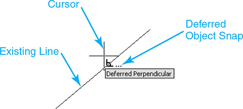
Deferred object snaps allow you to “build” the object snap point by selecting additional points and/or objects. When an object snap is deferred, there is an ellipsis (...) displayed after the object snap AutoSnap marker, indicating that there are more selections required (see Figure 5-19).
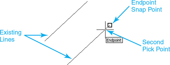
Endpoint
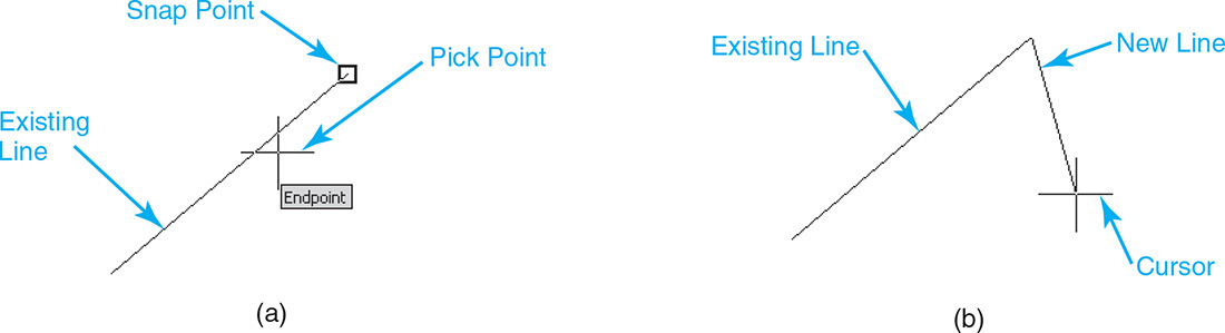
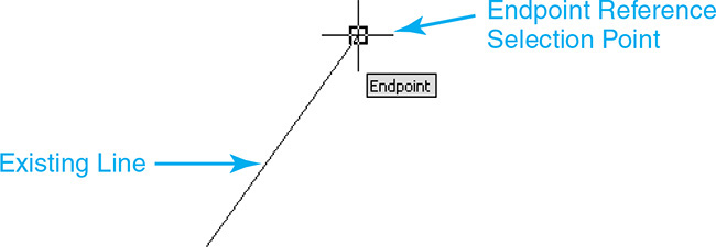
Endpoint is easily the most used object snap. The Endpoint object snap snaps to the closest endpoint of an arc, elliptical arc, line, multiline, polyline, spline, region, or ray. The Endpoint object snap will also snap to the closest corner of a trace, solid, or 3D face. Figures 5-20A and B show how to snap to the endpoint of a line using the Endpoint object snap when drawing a line.
Midpoint
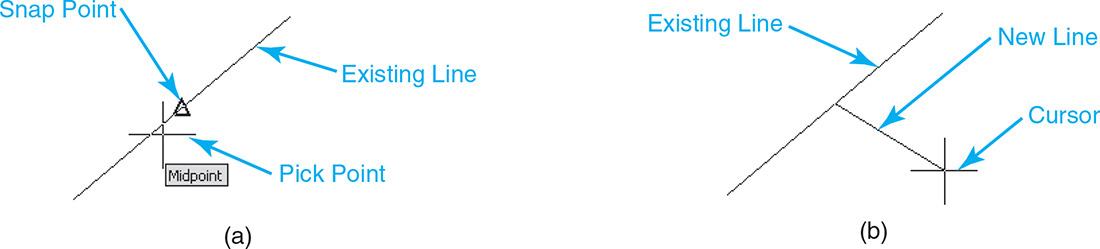
The Midpoint object snap snaps to the midway point of an arc, ellipse, elliptical arc, line, multiline, polyline, region, solid, spline, or Xline. The selected object is bisected exactly at the halfway point. Figures 5-21A and B show how to snap to the midpoint of a line using the Midpoint object snap when drawing a line.
Intersection
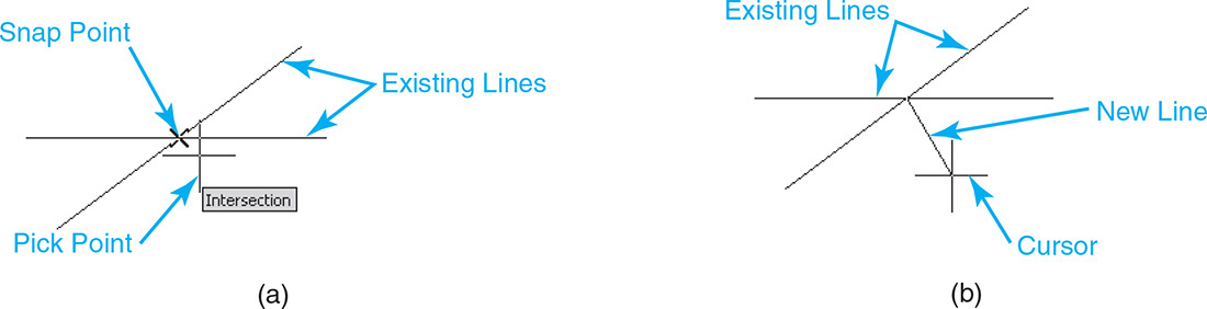
The Intersection object snap snaps to the intersection of two objects. The two objects can be any combination of the following: arc, circle, ellipse, elliptical arc, line, multiline, polyline, ray, region, spline, or Xline. Figures 5-22A and B show how to snap to the intersection of two lines using the Intersection object snap when drawing a line.
It is also possible to snap to the intersection of two objects that do not physically cross in your drawing but would intersect if either of them, or both, were extended. The Extended Intersection object snap snaps to the implied intersection of two objects. This extension mode occurs automatically through the deferred pick point process explained earlier. If you do not pick close to the physical intersection of two objects when using the Intersection object snap, AutoCAD automatically puts you in Extended Intersection mode and displays the Extended Intersection AutoSnap marker (Figure 5-23A).
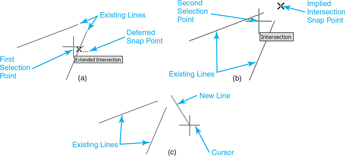
Figure 5-23 A Using the Extended Intersection object snap—Step 1 B Using the Extended Intersection object snap—Step 2 C Using the Extended Intersection object snap—Step 3
Remember that any time you see the ellipsis (...) next to an AutoSnap marker it means AutoCAD is waiting for more input. If you move your cursor over the other object that would intersect if it were extended, the typical Intersection AutoSnap marker is displayed (Figure 5-23B).
As soon as the Intersection AutoSnap marker is displayed, you can pick a point, and it will snap to the implied intersection (Figure 5-23C).
Tip
Extended Intersection is not available as a running object snap.
Exercise 5-4 Using the Endpoint, Midpoint, and Intersection Object Snaps
![]() Continue from Exercise 5-3.
Continue from Exercise 5-3.
![]() Turn off all the drawing tool buttons on the status bar.
Turn off all the drawing tool buttons on the status bar.
![]() Click on the down arrow menu to the right of the Object Snap button on the status bar and select Object SnapSettings... from the shortcut menu. The Object Snap tab of the Drafting Settings dialog box is displayed (see Figure 5-17).
Click on the down arrow menu to the right of the Object Snap button on the status bar and select Object SnapSettings... from the shortcut menu. The Object Snap tab of the Drafting Settings dialog box is displayed (see Figure 5-17).
![]() Select the Clear All button to clear any running object snaps. Turn on the Endpoint, Midpoint, and Intersection object snaps. Exit the Drafting Settings dialog box by selecting OK.
Select the Clear All button to clear any running object snaps. Turn on the Endpoint, Midpoint, and Intersection object snaps. Exit the Drafting Settings dialog box by selecting OK.
![]() Turn on the Object Snap button on the status bar.
Turn on the Object Snap button on the status bar.
![]() Start the LINE command.
Start the LINE command.
![]() Place your cursor over the bottom corner of the rotated square on the top of the drawing and wait until the Endpoint AutoSnap marker and tooltip are displayed. Pick a point while the AutoSnap marker is displayed (see Figure 5-24).
Place your cursor over the bottom corner of the rotated square on the top of the drawing and wait until the Endpoint AutoSnap marker and tooltip are displayed. Pick a point while the AutoSnap marker is displayed (see Figure 5-24).
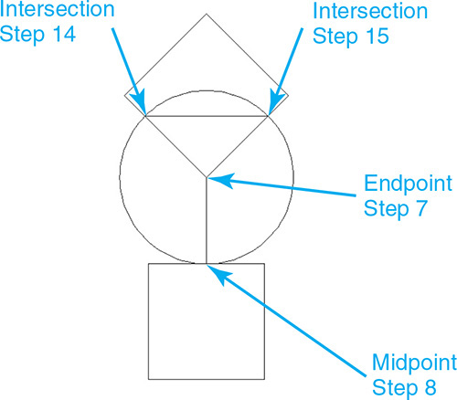
![]() Place your cursor over the middle of the top line of the square on the bottom of the drawing and wait until the Midpoint AutoSnap marker and tooltip are displayed. Pick a point while the AutoSnap marker is displayed (see Figure 5-24).
Place your cursor over the middle of the top line of the square on the bottom of the drawing and wait until the Midpoint AutoSnap marker and tooltip are displayed. Pick a point while the AutoSnap marker is displayed (see Figure 5-24).
![]() Press <Enter> to end the LINE command.
Press <Enter> to end the LINE command.
![]() Start the CIRCLE command.
Start the CIRCLE command.
![]() Choose the same point selected in step 7 to locate the circle center point.
Choose the same point selected in step 7 to locate the circle center point.
![]() Choose the same point selected in step 8 to indicate the circle radius.
Choose the same point selected in step 8 to indicate the circle radius.
![]() Start the LINE command.
Start the LINE command.
![]() Place your cursor over the intersection on the left side of the circle and bottom left angled line of the rotated square and wait until the Intersection AutoSnap marker and tooltip are displayed. Pick a point while the AutoSnap marker is displayed (see Figure 5-24).
Place your cursor over the intersection on the left side of the circle and bottom left angled line of the rotated square and wait until the Intersection AutoSnap marker and tooltip are displayed. Pick a point while the AutoSnap marker is displayed (see Figure 5-24).
![]() Place your cursor over the intersection on the right side of the circle and bottom right angled line of the rotated square and wait until the Intersection AutoSnap marker and tooltip are displayed. Pick a point while the AutoSnap marker is displayed (see Figure 5-24).
Place your cursor over the intersection on the right side of the circle and bottom right angled line of the rotated square and wait until the Intersection AutoSnap marker and tooltip are displayed. Pick a point while the AutoSnap marker is displayed (see Figure 5-24).
![]() Hit <Enter> to end the LINE command.
Hit <Enter> to end the LINE command.
![]() Save your drawing. Your drawing should look like Figure 5-24.
Save your drawing. Your drawing should look like Figure 5-24.
Apparent Intersection
The Apparent Intersection object snap snaps to the visual intersection of two objects that are not in the same plane in 3D space so they don’t physically intersect but appear to intersect when viewed from certain angles. Its use is reserved for working in 3D drawings.
Center
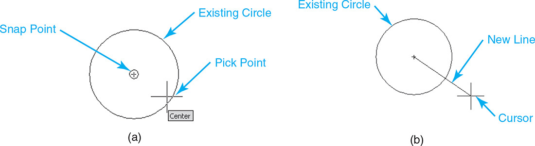
The Center object snap snaps to the center of an arc, circle, ellipse, or elliptical arc. Figures 5-25A and B show how to snap to the center of a circle using the Center object snap when drawing a line.
Tip
You can pick a center point by selecting either near the center or near the edge of a circle.
Quadrant
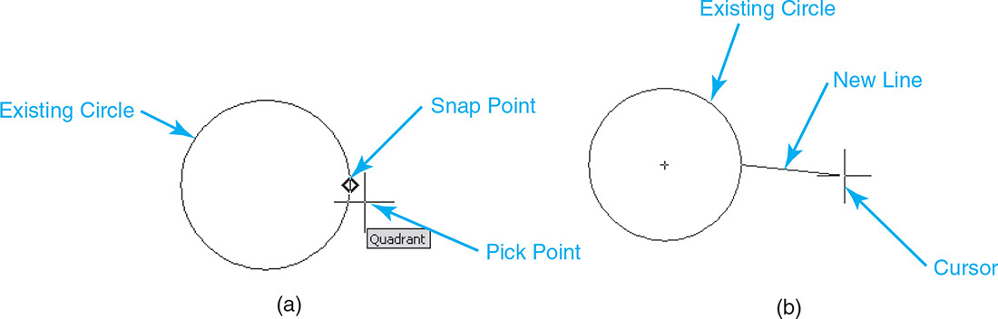
The Quadrant object snap snaps to one of the four quadrant points (0°, 90°, 180°, or 270°) of an arc, circle, ellipse, or elliptical arc. The quadrant point selected is the one closest to where you select the object. Figures 5-26A and B show how to snap to the 0° quadrant point of a circle using the Quadrant object snap when drawing a line.
Exercise 5-5 Using the Center and Quadrant Object Snaps
![]() Start a new drawing using the acad.dwt drawing template.
Start a new drawing using the acad.dwt drawing template.
![]() Select Zoom Extents to zoom to the limits of the drawing.
Select Zoom Extents to zoom to the limits of the drawing.
![]() Start the CIRCLE command. AutoCAD prompts you to Specify center point for circle or
Start the CIRCLE command. AutoCAD prompts you to Specify center point for circle or ![]() .
.
![]() Type 2,2<Enter>. AutoCAD prompts you to Specify radius of circle or
Type 2,2<Enter>. AutoCAD prompts you to Specify radius of circle or ![]() .
.
![]() Type 1<Enter> to specify a radius of 1″.
Type 1<Enter> to specify a radius of 1″.
![]() Repeat steps 4 and 5 to create two more 1″-radius circles at the coordinate locations of (4,5) and (6,2) (see Figure 5-27).
Repeat steps 4 and 5 to create two more 1″-radius circles at the coordinate locations of (4,5) and (6,2) (see Figure 5-27).
![]() Turn off all the drawing tool buttons on the status bar.
Turn off all the drawing tool buttons on the status bar.
![]() Click on the down arrow menu to the right of the Object Snap button on the status bar and select Object SnapSettings... from the shortcut menu. The Object Snap tab of the Drafting Settings dialog box is displayed (see Figure 5-17).
Click on the down arrow menu to the right of the Object Snap button on the status bar and select Object SnapSettings... from the shortcut menu. The Object Snap tab of the Drafting Settings dialog box is displayed (see Figure 5-17).
![]() Select the Clear All button to clear any running object snaps. Turn on the Center and Quadrant object snaps. Turn the Object Snap On check box on in the upper left corner. Exit the Drafting Settings dialog box by selecting OK.
Select the Clear All button to clear any running object snaps. Turn on the Center and Quadrant object snaps. Turn the Object Snap On check box on in the upper left corner. Exit the Drafting Settings dialog box by selecting OK.
![]() Start the LINE command.
Start the LINE command.
![]() Place your cursor over the center of the circle on the bottom left of the drawing, and wait until the Center AutoSnap marker and tooltip are displayed. Pick a point while the AutoSnap marker is displayed (see Figure 5-27).
Place your cursor over the center of the circle on the bottom left of the drawing, and wait until the Center AutoSnap marker and tooltip are displayed. Pick a point while the AutoSnap marker is displayed (see Figure 5-27).
![]() Repeat step 11 for the other two circles and draw three lines to create a triangle (see Figure 5-27).
Repeat step 11 for the other two circles and draw three lines to create a triangle (see Figure 5-27).
![]() Select the Close option. AutoCAD closes the triangle and exits the LINE command.
Select the Close option. AutoCAD closes the triangle and exits the LINE command.
![]() Start the LINE command.
Start the LINE command.
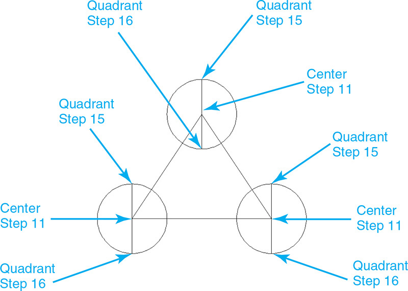
![]() Place your cursor over the top quadrant point (90°) of the circle on the bottom left of the drawing, and wait until the Quadrant AutoSnap marker and tooltip are displayed. Pick a point while the AutoSnap marker is displayed (see Figure 5-27).
Place your cursor over the top quadrant point (90°) of the circle on the bottom left of the drawing, and wait until the Quadrant AutoSnap marker and tooltip are displayed. Pick a point while the AutoSnap marker is displayed (see Figure 5-27).
![]() Place your cursor over the bottom quadrant point (270°) of the circle on the bottom left of the drawing, and wait until the Quadrant AutoSnap marker and tooltip are displayed. Pick a point while the AutoSnap marker is displayed (see Figure 5-27).
Place your cursor over the bottom quadrant point (270°) of the circle on the bottom left of the drawing, and wait until the Quadrant AutoSnap marker and tooltip are displayed. Pick a point while the AutoSnap marker is displayed (see Figure 5-27).
![]() Repeat steps 14 through 16 to create vertical lines from quadrant to quadrant on the other two circles.
Repeat steps 14 through 16 to create vertical lines from quadrant to quadrant on the other two circles.
![]() Save your drawing as CH5_EXERCISE5. Your drawing should look like Figure 5-27.
Save your drawing as CH5_EXERCISE5. Your drawing should look like Figure 5-27.
Tangent
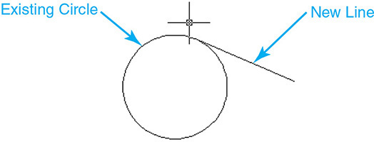
The Tangent object snap snaps to the tangent of an arc, circle, ellipse, elliptical arc, or spline. Figures 5-28A and B show how to snap to the tangent of a circle using the Tangent object snap when drawing a line.

It is possible to defer a tangent point by first selecting the object you want to be tangent to before picking any other points. Picking a circle first displays the Deferred Tangent AutoSnap marker (Figure 5-29A).
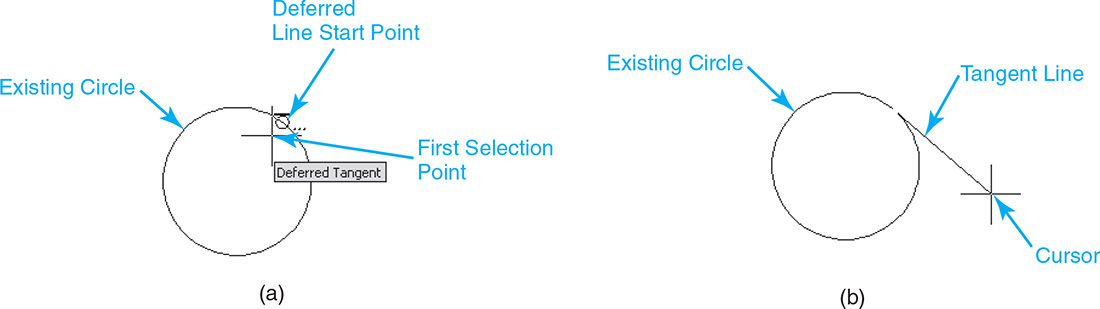
Figure 5-29 A Using the Deferred Tangent object snap—Step 1 B Using the Deferred Tangent object snap—Step 2
Again, the ellipsis (...) next to an AutoSnap marker means AutoCAD is waiting for more input. Pick another point to locate the end of the line (Figure 5-29B).
Exercise 5-6 Using the Tangent Object Snap
![]() Continue from Exercise 5-5.
Continue from Exercise 5-5.
![]() Start the LINE command.
Start the LINE command.
![]() Hold down the <Shift> key on your keyboard while right-clicking with your mouse to display the Object Snap shortcut menu (see Figure 5-16).
Hold down the <Shift> key on your keyboard while right-clicking with your mouse to display the Object Snap shortcut menu (see Figure 5-16).
![]() Select the Tangent object snap from the menu.
Select the Tangent object snap from the menu.
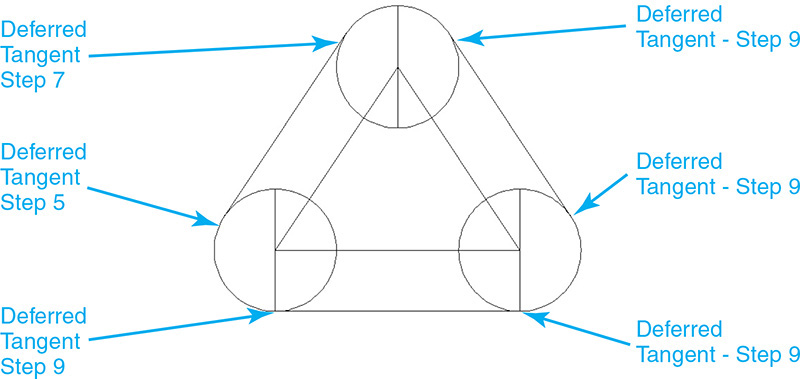
![]() Place your cursor over the left side of the circle on the bottom left of the drawing, and wait until the Deferred Tangent AutoSnap marker and tooltip are displayed. Pick a point while the AutoSnap marker is displayed (see Figure 5-30).
Place your cursor over the left side of the circle on the bottom left of the drawing, and wait until the Deferred Tangent AutoSnap marker and tooltip are displayed. Pick a point while the AutoSnap marker is displayed (see Figure 5-30).
![]() Repeat steps 3 and 4 to select the Tangent object snap again.
Repeat steps 3 and 4 to select the Tangent object snap again.
![]() Place your cursor over the left side of the circle on the top middle of the drawing, and wait until the Deferred Tangent AutoSnap marker and tooltip are displayed. Pick a point while the AutoSnap marker is displayed (see Figure 5-30).
Place your cursor over the left side of the circle on the top middle of the drawing, and wait until the Deferred Tangent AutoSnap marker and tooltip are displayed. Pick a point while the AutoSnap marker is displayed (see Figure 5-30).
![]() There should now be a line segment tangent to both circles.
There should now be a line segment tangent to both circles.
![]() Repeat steps 2 through 7 and create two more line segments tangent to the other two circles (see Figure 5-30).
Repeat steps 2 through 7 and create two more line segments tangent to the other two circles (see Figure 5-30).
![]() Save your drawing. Your drawing should look like Figure 5-30.
Save your drawing. Your drawing should look like Figure 5-30.
Perpendicular
The Perpendicular object snap snaps to a point perpendicular to an arc, circle, ellipse, elliptical arc, line, multiline, polyline, ray, region, solid, spline, or Xline. Figures 5-31A and B show how to draw a line perpendicular to another line using the Perpendicular object snap.
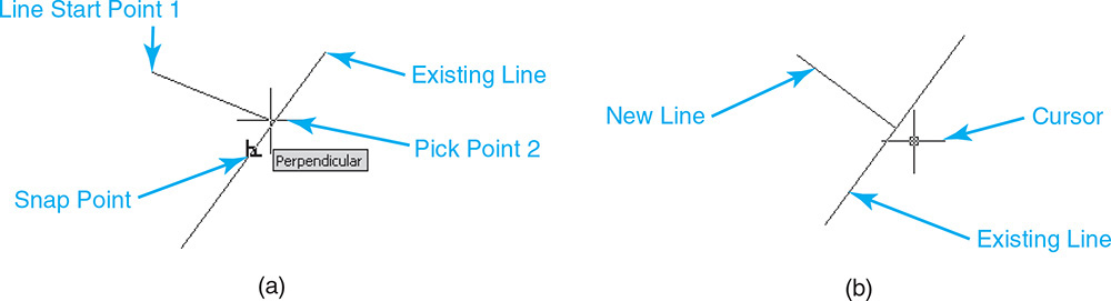
Figure 5-31 A Using the Perpendicular object snap—Step 1 B Using the Perpendicular object snap—Step 2
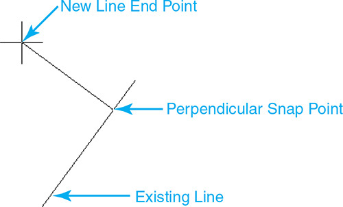
It is possible to defer a perpendicular point by first selecting the object you want to be perpendicular to before picking any other points. Picking a line first displays the Deferred Perpendicular AutoSnap marker (see Figure 5-32A).

Again, the ellipsis (...) next to an AutoSnap marker means AutoCAD is waiting for more input. Pick another point to locate the end of the line, which in turn determines where the new line attaches to the existing line (see Figure 5-32B).
Exercise 5-7 Using the Perpendicular Object Snap
![]() Continue from Exercise 5-6.
Continue from Exercise 5-6.
![]() Turn off all the drawing tool buttons on the status bar.
Turn off all the drawing tool buttons on the status bar.
![]() Click on the down arrow menu to the right of the Object Snap button on the status bar and select Object SnapSettings... from the shortcut menu. The Object Snap tab of the Drafting Settings dialog box is displayed (see Figure 5-17).
Click on the down arrow menu to the right of the Object Snap button on the status bar and select Object SnapSettings... from the shortcut menu. The Object Snap tab of the Drafting Settings dialog box is displayed (see Figure 5-17).
![]() Select the Clear All button to clear any running object snaps. Turn on the Perpendicular object snap. Turn the Object Snap On check box on in the upper left corner. Exit the Drafting Settings dialog box by selecting OK.
Select the Clear All button to clear any running object snaps. Turn on the Perpendicular object snap. Turn the Object Snap On check box on in the upper left corner. Exit the Drafting Settings dialog box by selecting OK.
![]() Start the LINE command. AutoCAD prompts you to Specify first point:.
Start the LINE command. AutoCAD prompts you to Specify first point:.
![]() Type 8,6<Enter>. AutoCAD prompts you to Specify next point or
Type 8,6<Enter>. AutoCAD prompts you to Specify next point or ![]() .
.
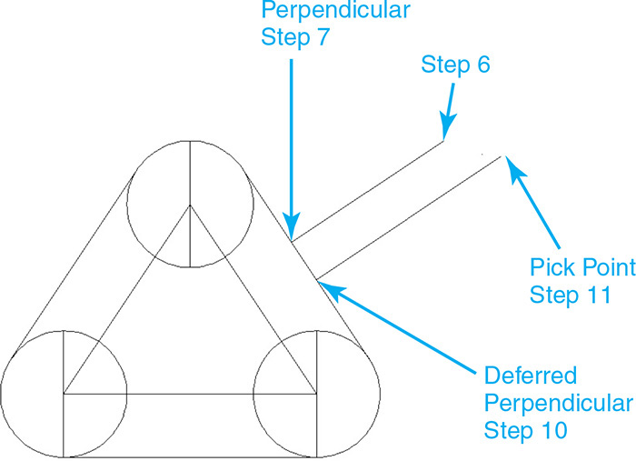
![]() Place your cursor over the angled line on the right side of the triangle, and wait until the Perpendicular AutoSnap marker and tooltip are displayed. Pick a point while the AutoSnap marker is displayed (see Figure 5-33).
Place your cursor over the angled line on the right side of the triangle, and wait until the Perpendicular AutoSnap marker and tooltip are displayed. Pick a point while the AutoSnap marker is displayed (see Figure 5-33).
![]() Type <Enter> to end the LINE command.
Type <Enter> to end the LINE command.
![]() Start the LINE command again.
Start the LINE command again.
![]() Place your cursor over the angled line on the right side of the triangle, and wait until the Deferred Perpendicular AutoSnap marker and tooltip are displayed. Pick a point while the AutoSnap marker is displayed (see Figure 5-33).
Place your cursor over the angled line on the right side of the triangle, and wait until the Deferred Perpendicular AutoSnap marker and tooltip are displayed. Pick a point while the AutoSnap marker is displayed (see Figure 5-33).
![]() Move your cursor up to the right and pick another point to create a perpendicular line segment (see Figure 5-33).
Move your cursor up to the right and pick another point to create a perpendicular line segment (see Figure 5-33).
![]() Type <Enter> to end the LINE command.
Type <Enter> to end the LINE command.
![]() Save your drawing. Your drawing should look like Figure 5-33.
Save your drawing. Your drawing should look like Figure 5-33.
Insert
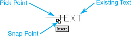
The Insert object snap snaps to the insertion point of an attribute, block, shape, or text. Figure 5-34 shows how to snap to the insertion point of a text object using the Insert object snap.
Node
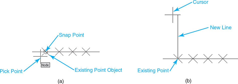
The Node object snap snaps to a point object, dimension definition point, or dimension text origin. Figures 5-35A and B show how to snap to a point created using the DIVIDE or MEASURE command and the Node object snap when drawing a line.
Nearest
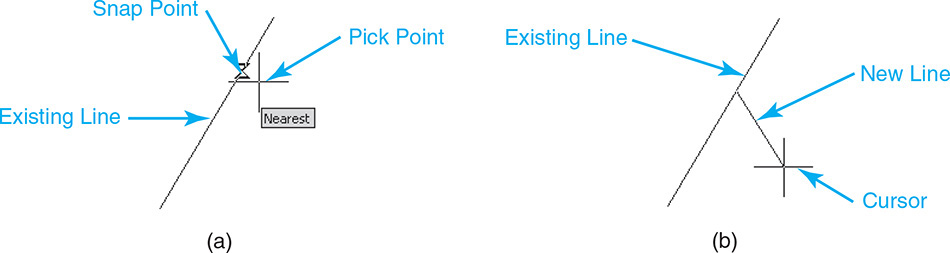
The Nearest object snap snaps to the nearest point on an arc, circle, ellipse, elliptical arc, line, multiline, point, polyline, ray, spline, or Xline. This allows you to pick a point near an object and be assured that it snaps directly on the object. Figures 5-36A and B show how to snap to a point exactly on a line using the Nearest object snap when drawing a line.
None
The None object snap allows you to snap to nothing . . . literally. The None object snap temporarily disables any running object snaps set on the Object Snap tab of the Drafting Settings dialog box for the next picked point. This makes it possible to pick a point in your drawing that doesn’t snap to any objects that might be nearby, particularly when you are working in close quarters. You can always turn the Object Snap button off on the status bar at any time as well, but then you have to turn it back on when you need object snaps enabled again.
Advanced Object Snap Modes
The following object snaps are more advanced than those introduced in the previous section. The object snaps in this section require additional information to build the snap point based on the geometry of an existing object, or even objects. This can range from entering an offset distance to acquiring points that are used to display alignment paths (see Figure 5-37).
Some acquired points are selected automatically by simply moving your cursor over an object, whereas others require that you explicitly pick a point in the drawing.
acquired point: Object tracking feature used to locate a point as an intermediate location in order to locate temporary alignment paths.
The difference between the two methods of acquiring points is highlighted in the following sections to help reduce any confusion.
From
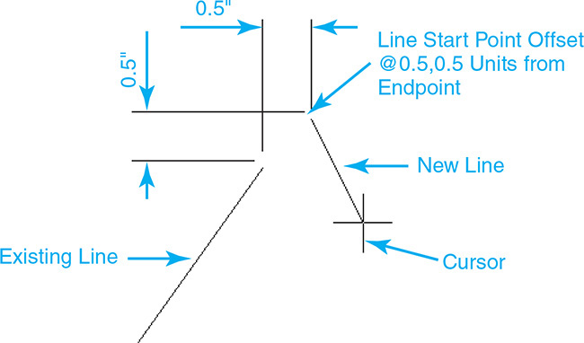
The From object snap allows you to specify a relative distance from a selected point and is typically used in conjunction with other object snaps. The distance can be entered either as a relative Cartesian coordinate using the format @X,Y (for example, @2,2) or as a polar coordinate using the distance and angle format (for example, @2<45). Figures 5-38A and B show how to snap to a point that is 0.5″ to the right and 0.5″ above the endpoint of a line using the From object snap.
Exercise 5-8 Using the From Object Snap
![]() Create a 2 × 2 square using the steps in Exercise 5-2 on pages 169–170.
Create a 2 × 2 square using the steps in Exercise 5-2 on pages 169–170.
![]() Turn off all the drawing tool buttons on the status bar.
Turn off all the drawing tool buttons on the status bar.
![]() Click on the down arrow menu to the right of the Object Snap button on the status bar and select Object SnapSettings... from the shortcut menu. The Object Snap tab of the Drafting Settings dialog box is displayed (see Figure 5-17).
Click on the down arrow menu to the right of the Object Snap button on the status bar and select Object SnapSettings... from the shortcut menu. The Object Snap tab of the Drafting Settings dialog box is displayed (see Figure 5-17).
![]() Select the Clear All button to clear any running object snaps. Turn on the Endpoint object snap. Turn the Object Snap On check box on in the upper left corner. Exit the Drafting Settings dialog box by selecting OK.
Select the Clear All button to clear any running object snaps. Turn on the Endpoint object snap. Turn the Object Snap On check box on in the upper left corner. Exit the Drafting Settings dialog box by selecting OK.
Note
Specifying an absolute coordinate without the @ symbol will simply locate the point at the coordinate specified.
![]() Start the CIRCLE command. AutoCAD prompts you to Specify center point for circle or
Start the CIRCLE command. AutoCAD prompts you to Specify center point for circle or ![]() .
.
![]() Hold down the <Shift> key on your keyboard while right-clicking with your mouse to display the Object Snap shortcut menu (see Figure 5-16).
Hold down the <Shift> key on your keyboard while right-clicking with your mouse to display the Object Snap shortcut menu (see Figure 5-16).
![]() Select the From object snap from the menu. AutoCAD prompts you for a base point:
Select the From object snap from the menu. AutoCAD prompts you for a base point:
Base point:
![]() Place your cursor over the endpoints on the bottom left corner of the square, and wait until the Endpoint AutoSnap marker and tooltip are displayed. Pick a point while the AutoSnap marker is displayed (see Figure 5-39).
Place your cursor over the endpoints on the bottom left corner of the square, and wait until the Endpoint AutoSnap marker and tooltip are displayed. Pick a point while the AutoSnap marker is displayed (see Figure 5-39).
![]() AutoCAD then prompts you for an offset distance:
AutoCAD then prompts you for an offset distance:
<Offset>:
![]() Type @.5,.5<Enter>. AutoCAD locates the center point of the circle and prompts you for a radius:
Type @.5,.5<Enter>. AutoCAD locates the center point of the circle and prompts you for a radius:
Specify radius of circle or ![]() .
.
![]() Type .25<Enter>.
Type .25<Enter>.
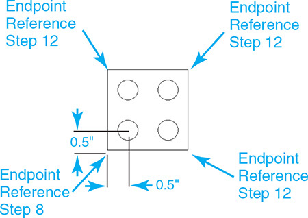
![]() Repeat steps 5 through 11 to locate three more circles with a 0.25 radius a half inch in from each corner (see Figure 5-39).
Repeat steps 5 through 11 to locate three more circles with a 0.25 radius a half inch in from each corner (see Figure 5-39).
![]() Save your drawing as CH5_EXERCISE8. Your drawing should look like Figure 5-39.
Save your drawing as CH5_EXERCISE8. Your drawing should look like Figure 5-39.
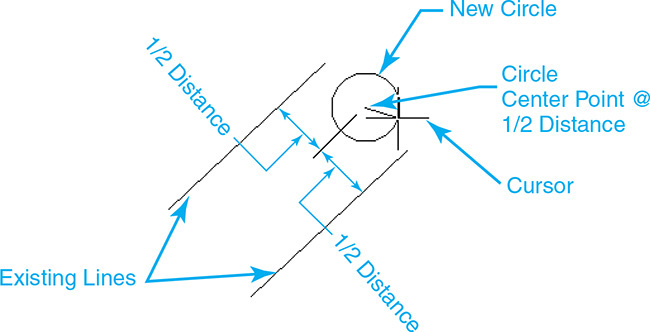
Mid Between 2 Points
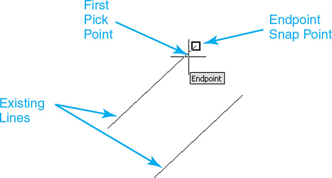
The Mid Between 2 Points object snap allows you to locate a snap point midway between two points and is typically used in conjunction with other object snaps so that you can locate the point precisely. Figures 5-40A through C show how to snap midway between the endpoints of two lines using the Mid Between 2 Points object snap when drawing a circle.
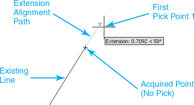
Extension
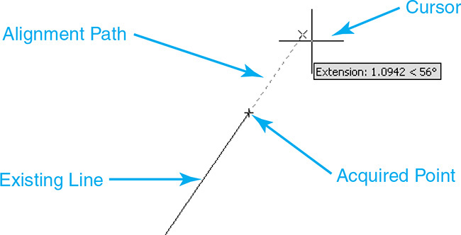
The Extension object snap allows you to display an alignment path along the extension of an arc, elliptical arc, line, multiline, polyline, region, or ray by acquiring an endpoint on one or more objects.
A point is acquired by simply moving your cursor over an endpoint of a valid object type. You do not need to pick a point to acquire it when using the Extension object snap. A small cross is displayed after a point is acquired. You can deselect an acquired point by moving your cursor back over the acquired point so the cross disappears.
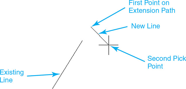
After a point is acquired, you display an alignment path by moving your cursor in the object’s extension direction. Once the alignment path is displayed, you can locate a point by picking a point on the path or by using direct distance entry to specify a distance to travel along the vector. Figures 5-41A and B show how to locate a line start point on the extension alignment path of a line using the Extension object snap.
Exercise 5-9 Using the Extension Object Snap
![]() Continue from Exercise 5-8.
Continue from Exercise 5-8.
![]() Turn on the Ortho Mode button on the status bar.
Turn on the Ortho Mode button on the status bar.
![]() Click on the down arrow menu to the right of the Object Snap button on the status bar and select Object Snap Settings... from the shortcut menu. The Object Snap tab of the Drafting Settings dialog box is displayed (see Figure 5-17).
Click on the down arrow menu to the right of the Object Snap button on the status bar and select Object Snap Settings... from the shortcut menu. The Object Snap tab of the Drafting Settings dialog box is displayed (see Figure 5-17).
![]() Select the Clear All button to clear any running object snaps. Turn on the Extension object snap. Turn the Object Snap On check box on in the upper left corner. Exit the Drafting Settings dialog box by selecting OK.
Select the Clear All button to clear any running object snaps. Turn on the Extension object snap. Turn the Object Snap On check box on in the upper left corner. Exit the Drafting Settings dialog box by selecting OK.
![]() Start the LINE command.
Start the LINE command.
![]() Place your cursor over the endpoints on the bottom left corner of the square to acquire a point (see Figure 5-42).
Place your cursor over the endpoints on the bottom left corner of the square to acquire a point (see Figure 5-42).
![]() Move your cursor to the left of the corner to display a horizontal alignment path and tooltip indicating you are pointing at 180° (see Figure 5-42).
Move your cursor to the left of the corner to display a horizontal alignment path and tooltip indicating you are pointing at 180° (see Figure 5-42).
![]() Type 1<Enter>.
Type 1<Enter>.
![]() AutoCAD uses direct distance entry to place a point 1 unit from the lower left corner along the 180° horizontal extension alignment path (see Figure 5-42).
AutoCAD uses direct distance entry to place a point 1 unit from the lower left corner along the 180° horizontal extension alignment path (see Figure 5-42).
![]() Place your cursor over the endpoints on the top left corner of the square to acquire another point (see Figure 5-42).
Place your cursor over the endpoints on the top left corner of the square to acquire another point (see Figure 5-42).
![]() Move your cursor to the left to display a horizontal alignment path and tooltip indicating you are pointing at 180° (see Figure 5-42).
Move your cursor to the left to display a horizontal alignment path and tooltip indicating you are pointing at 180° (see Figure 5-42).
![]() Use Ortho mode to pick a point on the alignment path 90° from the first point (see Figure 5-42).
Use Ortho mode to pick a point on the alignment path 90° from the first point (see Figure 5-42).
![]() Save your drawing. Your drawing should look like Figure 5-42.
Save your drawing. Your drawing should look like Figure 5-42.
Parallel
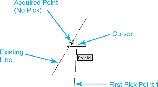
The Parallel object snap allows you to draw a parallel line using a parallel alignment path. The alignment path is displayed by acquiring a point on the line segment to which you want to draw a parallel line when AutoCAD prompts you for the second point of a line.
A Parallel object snap point is acquired by moving your cursor over the desired line segment. You do not need to pick a point to acquire it when using the Parallel object snap. When you move your cursor over a line segment after selecting the Parallel object snap, the Parallel AutoSnap marker is displayed, and a point is acquired showing a small cross. You can deselect an acquired point by moving your cursor back over the acquired point so the cross disappears.
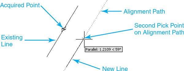
After a point is acquired, you display a parallel alignment path by moving your cursor in the parallel direction. Once the alignment path is displayed, you can locate a point by picking a point on the path or by using direct distance entry to specify a distance to travel along the vector. Figures 5-43A and B show how to draw a line parallel to another line using the Parallel object snap when drawing a line.
Object Snap Tracking
Object snap tracking relies on the AutoTracking feature (explained earlier in the “Polar Tracking” section) to display alignment paths at orthogonal or polar angle settings using points you select in your drawing using object snaps. The angle settings used, polar or orthogonal, are controlled in the Object Snap Tracking Settings section on the Polar Tracking tab of the Drafting Settings dialog box shown in Figure 5-44.
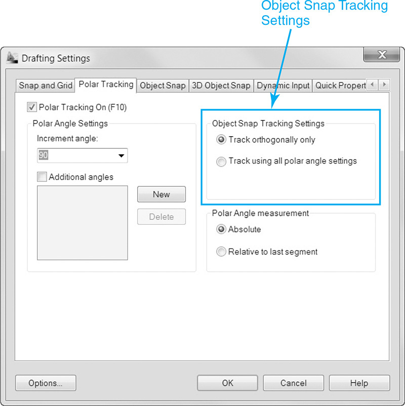
By default, object snap tracking is set to track orthogonally at horizontal and vertical angles. There are two types of object snap tracking:
• Temporary tracking
• Object snap tracking mode
Temporary tracking works like an object snap override to display tracking alignment paths on an as-needed basis at picked points. The object snap tracking mode works with running object snaps so that when it is turned on, tracking alignment paths are automatically displayed at all the currently running object snap points. Both types of tracking are explained in detail in the following sections.
Temporary Tracking
Temporary tracking is used on an as-needed basis to display AutoTrack alignment paths at acquired points and is typically used in conjunction with object snaps.
You must pick a point in your drawing to acquire a point when using temporary tracking. A small cross is displayed after a point is acquired. You can deselect an acquired point by moving your cursor back over the acquired point so the cross disappears.
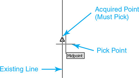
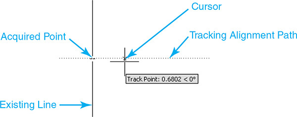
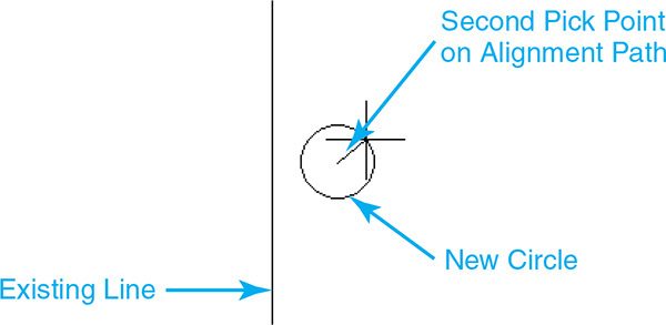
After a point is acquired, AutoTrack alignment paths are displayed at the angles specified on the Polar Tracking tab of the Drafting Settings dialog box. Once the alignment path is displayed, you can locate a point by picking a point on the path or by using direct distance entry to specify a distance to travel along the alignment vector. Figures 5-45A through C show how to locate the center point of a circle by tracking horizontally from the midpoint of a vertical line.
Object Snap Tracking
The Object Snap Tracking drawing tool works with running object snaps so that when object snap tracking mode is turned on, AutoTrack alignment paths can be displayed by acquiring a point at any currently running object snap point.
Object Snap Tracking |
|
Status Bar: |
|
Function Key: |
F11 |
Command Line: |
None |
Keyboard Combo: |
None |
Unlike with temporary tracking, when object snap tracking mode is on, you do not have to pick a point to acquire it. You just move your cursor over an object snap point, and a small cross (+) is displayed, indicating the point is acquired. You can deselect an acquired point by moving your cursor back over the acquired point so the cross disappears.
After a point is acquired, AutoTrack alignment paths are displayed at the angle specified on the Polar Tracking tab of the Drafting Settings dialog box. Once the alignment path is displayed, you can locate a point by picking a point on the path or by using direct distance entry to specify a distance to travel along the alignment vector.
Intersecting Alignment Paths
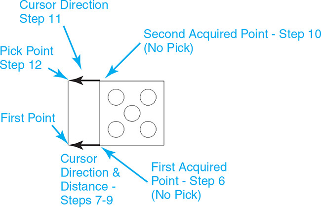
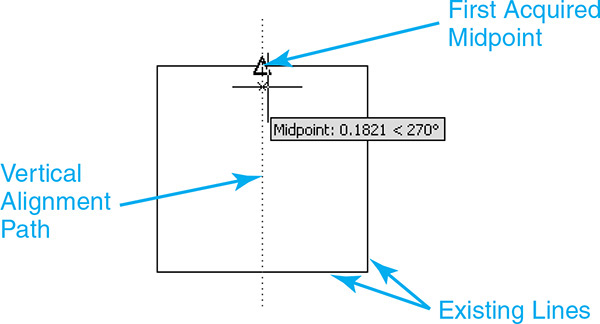
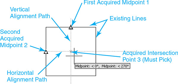
Both temporary tracking and object snap tracking allow you to display multiple AutoTrack alignment paths so that you can locate points relative to multiple objects in your drawing. When you use AutoTracking, each point you snap to displays its own alignment path. If multiple alignment paths cross, it is possible to snap to their point of intersection by putting your cursor over the intersection until a small cross appears that looks similar to an acquired point and then picking a point. Figures 5-46A through C show how to locate the center of a circle using the intersection point of vertical and horizontal AutoTrack alignment paths.
Exercise 5-10 Using Object Snap Tracking
![]() Continue from Exercise 5-9.
Continue from Exercise 5-9.
![]() Turn off all the drawing tool buttons on the status bar.
Turn off all the drawing tool buttons on the status bar.
![]() Click on the down arrow menu to the right of the Object Snap button on the status bar and select Object SnapSettings... from the shortcut menu. The Object Snap tab of the Drafting Settings dialog box is displayed (see Figure 5-17).
Click on the down arrow menu to the right of the Object Snap button on the status bar and select Object SnapSettings... from the shortcut menu. The Object Snap tab of the Drafting Settings dialog box is displayed (see Figure 5-17).
![]() Select the Clear All button to clear any running object snaps. Turn on the Midpoint object snap. Turn the Object Snap On check box on in the upper left corner. Exit the Drafting Settings dialog box by selecting the OK button.
Select the Clear All button to clear any running object snaps. Turn on the Midpoint object snap. Turn the Object Snap On check box on in the upper left corner. Exit the Drafting Settings dialog box by selecting the OK button.
![]() Turn on the Object Snap Tracking button on the status bar.
Turn on the Object Snap Tracking button on the status bar.
![]() Start the CIRCLE command. AutoCAD prompts you to Specify center point for circle or
Start the CIRCLE command. AutoCAD prompts you to Specify center point for circle or ![]() .
.
![]() Acquire a point at the middle point of the horizontal line on the top of the square by placing your cursor over the horizontal line so the Midpoint AutoSnap marker and tooltip are displayed. Do not pick a point (see Figure 5-47).
Acquire a point at the middle point of the horizontal line on the top of the square by placing your cursor over the horizontal line so the Midpoint AutoSnap marker and tooltip are displayed. Do not pick a point (see Figure 5-47).
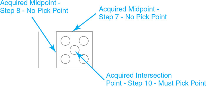
![]() Acquire a point at the middle point of the vertical line on the left of the square by placing your cursor over the vertical line so the Midpoint AutoSnap marker and tooltip are displayed. Do not pick a point (see Figure 5-47).
Acquire a point at the middle point of the vertical line on the left of the square by placing your cursor over the vertical line so the Midpoint AutoSnap marker and tooltip are displayed. Do not pick a point (see Figure 5-47).
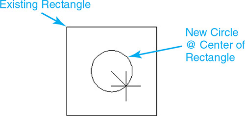
![]() Move your cursor to the middle of the rectangle to display both a horizontal alignment path with tooltip and a vertical alignment path with tooltip.
Move your cursor to the middle of the rectangle to display both a horizontal alignment path with tooltip and a vertical alignment path with tooltip.
![]() Pick a point when the two alignment paths cross and the small acquired intersection point marker (x) is displayed (see Figure 5-47).
Pick a point when the two alignment paths cross and the small acquired intersection point marker (x) is displayed (see Figure 5-47).
![]() AutoCAD locates the center point of the circle at the center of the rectangle and prompts you for a radius:
AutoCAD locates the center point of the circle at the center of the rectangle and prompts you for a radius:
Specify radius of circle or ![]() .
.
![]() Type .25<Enter>.
Type .25<Enter>.
![]() Save your drawing. Your drawing should look like Figure 5-47.
Save your drawing. Your drawing should look like Figure 5-47.
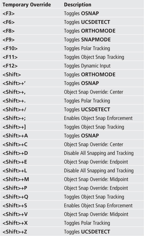
AutoCAD provides a keyboard feature for overriding the current object snap settings temporarily when AutoCAD is prompting for a point. It is referred to as a temporary override. Typically, an override consists of a keyboard combination that includes the <Shift> key. In fact, holding down the <Shift> key by itself when selecting a point temporarily puts AutoCAD in Ortho mode. The following table provides a complete list of temporary overrides:
Dynamic Input
As mentioned in Chapter 1, dynamic input is a set of related input and display features that allows you to enter information near the mouse cursor so you can focus on your drawing instead of constantly switching focus to the command line for command prompts and data entry.
The Dynamic Input interface consists of three different components:
• Pointer Input
• Dimension Input
• Dynamic Prompts
Dynamic Input |
|
Status Bar: |
|
Function Key: |
F12 |
Command Line: |
None |
Keyboard Combo: |
None |
Each of these different components is explained in the following sections.
Pointer Input
When Pointer Input is on, the coordinate location of the mouse crosshairs is displayed as x and y values in a tooltip near the cursor. As you move your mouse the coordinate values are dynamically updated to reflect the cursor’s new location. The pointer input for the first point of a line is shown in Figure 5-48.
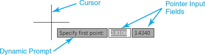
The pointer input tooltip consists of x and y input fields that you can update with a coordinate value of your choice via the keyboard using the same comma-delimited format used for entering coordinates at the command line by typing X,Y<Enter>. Entering the comma after the x value locks the input field for x and shifts focus to the y input field. Entering the desired y value and hitting <Enter> accepts the coordinate value.
Tip
It is also possible to use the <Tab> key to switch between the x and y coordinate input fields.
Dimension Input
When Dimension Input is on, distance and angle values are displayed in multiple tooltips near the cursor when a command prompts for a second point. The values in the dimension tooltips change as you move the cursor. The dimension input for the second point of a line is shown in Figure 5-49.
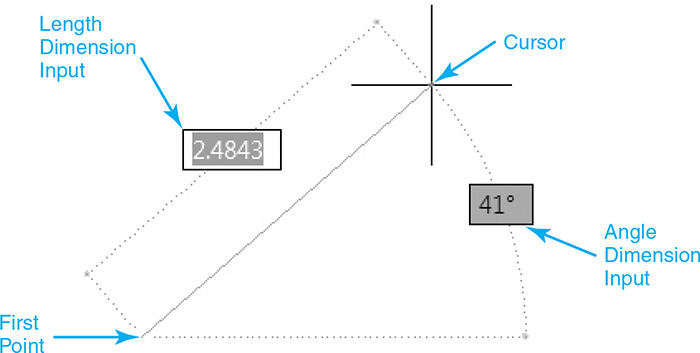
You can use the <Tab> key to switch between the different length and angle dimension input fields. When you use the <Tab> key, focus switches to another dimension input field while locking the previous field. Using this feature, you can input a length for a line and then press the <Tab> key to switch to the angle field to specify the angle. Any angle you input will create a line at that angle with the length previously entered in the length field. This process also works in reverse so that you can press the <Tab> key to enter the angle first and then press the <Tab> key again to enter the length. Now a line will be created at the preset input angle at any length specified.
If you enter an invalid value in any dimension input field, the value highlights automatically so you can enter a new value.
Dynamic Prompts
When Dynamic Prompts is on, command prompts and options are displayed in a tooltip near the cursor. You can type a response in the dynamic prompt input field instead of at the command line. The dynamic prompt for the POLYGON command is shown in Figure 5-50.

Dynamic Prompts also allows you to select command options near the cursor using the arrow keys on your keyboard. If a command has options, a down arrow is displayed in the dynamic prompt tooltip. Pressing the down arrow key displays the command options in a shortcut menu near the cursor. The ZOOM command options are shown in Figure 5-51.
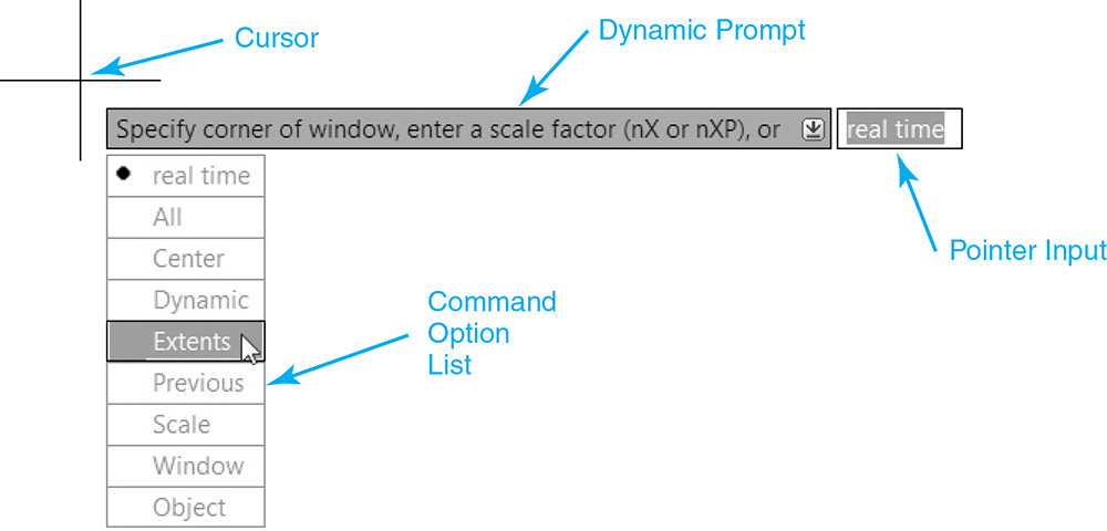
You can use your up and down arrow keys to navigate to the desired option and hit <Enter>, or you can select an option with your mouse pointer.
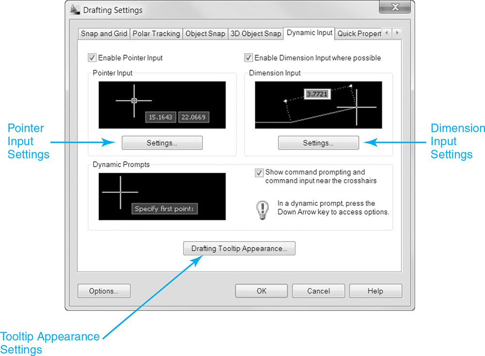
Dynamic Input Settings
The dynamic input settings are managed on the Dynamic Input tab of the Drafting Settings dialog box shown in Figure 5-52.
The following sections explain the different dynamic input settings.
Pointer Input Settings
You can turn Pointer Input on and off via the Enable Pointer Input check box. The Settings... button displays the Pointer Input Settings dialog box shown in Figure 5-53. This dialog box allows you to control the format and visibility of the pointer input coordinate tooltips.
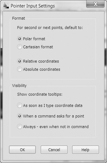
The different format settings are as follows:
• Polar format Enter the second or next point in polar coordinate format. Enter a comma (,) to change to Cartesian format.
• Cartesian format Enter the second or next point in Cartesian coordinate format. You can enter an angle symbol (<) to change to polar format.
• Relative coordinates Enter the second or next point in relative coordinate format. Enter a pound sign (#) to change to absolute format.
• Absolute coordinates Enter the second or next point in absolute coordinate format. Enter an at sign (@) to change to polar format.
The different visibility settings are as follows:
• As soon as I type coordinate data Displays tooltips only when you start to enter coordinate data
• When a command asks for a point Displays tooltips whenever a command prompts for a point
• Always - even when not in command Always displays tooltips when Pointer Input is turned on
Dimension Input Settings
You can turn Dimension Input on and off via the Enable Dimension Input where possible check box (see Figure 5-52). The Settings... button displays the Dimension Input Settings dialog box shown in Figure 5-54. This dialog box allows you to control the visibility of the dimension input coordinate tooltips when you are editing using grips.

The different visibility settings are as follows:
• Show only 1 dimension input field at a time Displays only the distance dimension input tooltip when you are using grips
• Show 2 dimension input fields at a time Displays the distance and angle dimension input tooltips when you are using grips
• Show the following dimension input fields simultaneously Displays the selected dimension input tooltips when you are using grips. You can select one or more of the check boxes
Dynamic Prompts
You can turn Dynamic Prompts on and off via the Show command prompting and command input near the crosshairs check box (see Figure 5-52).
Controlling the Drafting Tooltip Appearance
The Drafting Tooltip Appearance... button displays the Tooltip Appearance dialog box shown in Figure 5-55. This dialog box allows you to control the color, size, and transparency of the dynamic input tooltips.
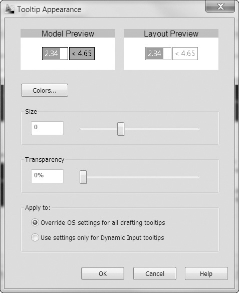
To change the color of the tooltip in both model space and layout space, select the Colors... button to display the Drawing Window Colors dialog box. The Drawing Window Colors dialog box allows you to change the tooltips in both environments by selecting the proper Context setting.
To change the size of tooltips, you can either move the slider to the right to make tooltips bigger or move it to the left to make tooltips smaller. The default size is 0.
To change the transparency of tooltips, you can either move the slider to the right to make tooltips more transparent or move it to the left to make them less transparent. A value of 0 makes the tooltips opaque.
You can choose to apply your changes using the following:
• Override OS settings for all drafting tooltips Applies the settings to all tooltips, overriding the settings in the operating system
• Use settings only for Dynamic Input tooltips Applies the settings only to the drafting tooltips used in dynamic input
Using Construction Lines
Construction lines are temporary lines that are used to help you lay out, or construct, a drawing. Using construction lines to create drawings is a technique that has been around since the early days of drafting. On the board, construction lines were typically drawn with very light lines that could be erased after the final drawing was created. Using AutoCAD, construction lines are typically created on a separate layer so you can control their visibility by turning them on and off.
For More Details
See Chapter 6 for detailed information on using layers to separate drawing information to control the visibility of objects.
Construction lines serve many purposes. Some of the more common uses of construction lines are:
• Creating multiple views of a mechanical drawing using orthographic projection
orthographic projection: The two-dimensional graphic representation of an object formed by the perpendicular intersections of lines drawn from points on the object to a plane of projection.
• Temporary locating of geometric features using object snaps and offset distances
• Creating architectural elevations based on features located on an existing floor plan, and vice versa
• Bisecting an angle
One of the classic uses of construction lines is in the creation of multiple views of a mechanical drawing using orthographic projection. See Figure 5-56.
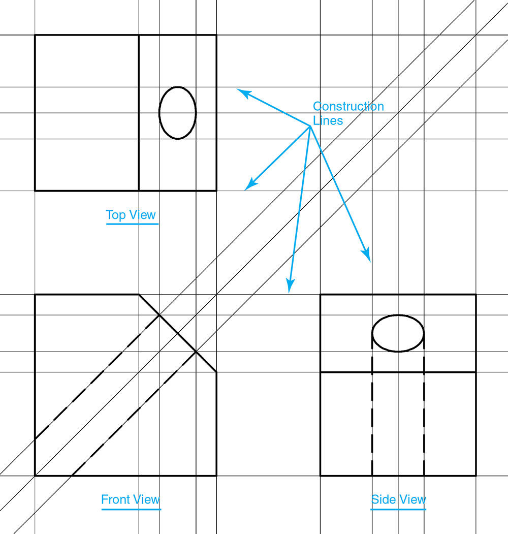
Using construction lines, you can create one view of a part (e.g., front, top, side) and then locate horizontal and vertical (orthographic) construction lines on key points of the part using the object snaps explained earlier in the chapter to project the points as construction lines in other views. You can then create the other views by drawing directly over the top of the construction lines using the Intersection object snap introduced earlier. Once you complete all the necessary views to describe the part, you can erase or turn off the construction line layer, and you have a finished drawing.
Using the construction line approach, you have to measure distances only once when you create the first view of the part. Most, if not all, of the other views can then be created by projecting construction lines from the original view, which you know is accurate. Theoretically, if you draw the part correctly in the first view, all the other views that are based on it should also be correct. Using construction lines is a great time-saving technique that increases production and promotes precision.
Construction Line |
|
Ribbon & Panel: |
Home | Draw
|
Menu: |
Draw | Construction Line |
Command Line: |
XLINE |
Command Alias: |
XL |

The XLINE Command
In AutoCAD, construction lines are referred to as Xlines and extend infinitely in both directions. This infinite property allows you to zoom or pan as far as necessary and always have the construction lines visible so you can reference them. Construction lines are created using the XLINE command.
The Zoom Extents tool is unaffected by Xline objects. Any Xlines that exist in a drawing are ignored when zooming to the drawing extents.
There are a number of different ways to create construction lines using the XLINE command:
• Using two pick points
• Horizontally
• Vertically
• Offset from an existing line
• Specified angle
• Bisected angle
The XLINE command options are explained in the following sections.
Drawing a Construction Line Using Two Points
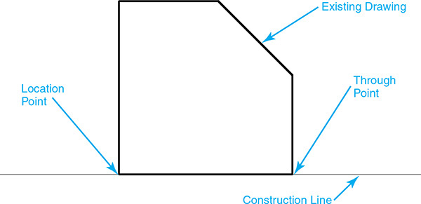
This is the default option for creating construction lines. To create an Xline using two points, select the XLINE command and pick two points. The first point locates the Xline, and the second point determines its angle. Typically you select points using the object snaps explained earlier in the chapter when creating construction lines so that the construction line is drawn relative to an existing object. See Figure 5-57.
Tip
The first point you select to create a construction line using two points becomes the midpoint of the construction line so that you can snap to it using the Midpoint object snap later.
Drawing Horizontal and Vertical Construction Lines
Horizontal and vertical construction lines are the two most popular XLINE command options because they help facilitate the creation of multiview drawings using orthographic projection.
To create a horizontal construction line, select the XLINE command and type H<Enter> at the command line or select Hor from the list of Dynamic Input command options. To create a vertical construction line, select the XLINE command and type V<Enter> at the command line or select Ver from the list of Dynamic Input command options. You then select a single point to locate the horizontal or vertical construction line in your drawing. AutoCAD continues to prompt for points until you type <Enter> so you can create as many construction lines as needed. See Figures 5-58A and B.
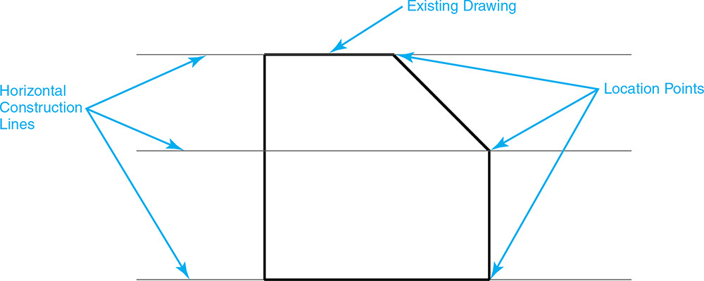
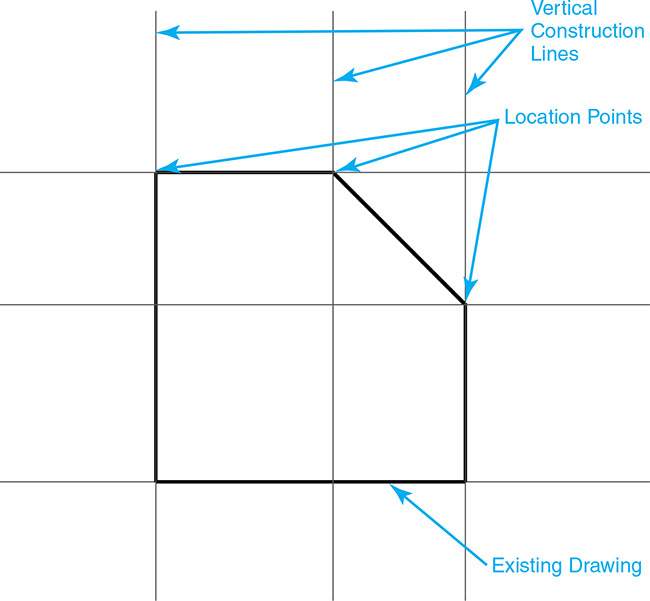
Exercise 5-11 Drawing Horizontal and Vertical Construction Lines
![]() Start a new drawing using the acad.dwt drawing template.
Start a new drawing using the acad.dwt drawing template.
![]() Create the drawing shown in Figure 5-59.
Create the drawing shown in Figure 5-59.
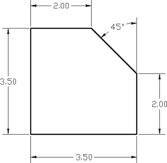
![]() Turn off all the drawing tool buttons on the status bar.
Turn off all the drawing tool buttons on the status bar.
![]() Click on the down arrow menu to the right of the Object Snap button on the status bar and select Object SnapSettings... from the shortcut menu. The Object Snap tab of the Drafting Settings dialog box is displayed (see Figure 5-17).
Click on the down arrow menu to the right of the Object Snap button on the status bar and select Object SnapSettings... from the shortcut menu. The Object Snap tab of the Drafting Settings dialog box is displayed (see Figure 5-17).
![]() Select the Clear All button to clear any running object snaps. Turn on the Endpoint, Midpoint, and Intersection object snaps. Exit the Drafting Settings dialog box by selecting OK.
Select the Clear All button to clear any running object snaps. Turn on the Endpoint, Midpoint, and Intersection object snaps. Exit the Drafting Settings dialog box by selecting OK.
![]() Turn on the Object Snap button on the status bar.
Turn on the Object Snap button on the status bar.
![]() Start the XLINE command.
Start the XLINE command.
![]() Select the Hor command option. AutoCAD prompts you for a through point:
Select the Hor command option. AutoCAD prompts you for a through point:
Specify through point:
![]() Create three horizontal construction lines by snapping to the three endpoints using the Endpoint object snap, as shown in Figure 5-58A.
Create three horizontal construction lines by snapping to the three endpoints using the Endpoint object snap, as shown in Figure 5-58A.
![]() Type <Enter> to end the XLINE command.
Type <Enter> to end the XLINE command.
![]() Start the XLINE command again.
Start the XLINE command again.
![]() Select the Ver command option. AutoCAD prompts you for a through point:
Select the Ver command option. AutoCAD prompts you for a through point:
Specify through point:
![]() Create three vertical construction lines by snapping to the three endpoints using the Endpoint object snap, as shown in Figure 5-58B.
Create three vertical construction lines by snapping to the three endpoints using the Endpoint object snap, as shown in Figure 5-58B.
![]() Type <Enter> to end the XLINE command.
Type <Enter> to end the XLINE command.
![]() Save your drawing as CH5_EXERCISE11. Your drawing should look like Figure 5-60.
Save your drawing as CH5_EXERCISE11. Your drawing should look like Figure 5-60.
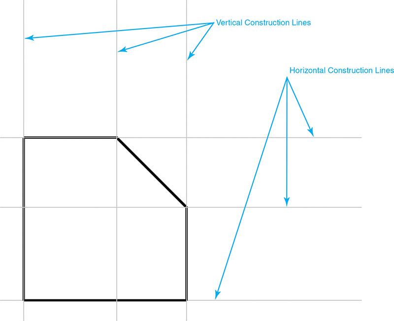
Offsetting Objects with Construction Lines
To further facilitate the layout and construction of a drawing, you can offset an existing line object (line, polyline, etc.) with a parallel construction line by either specifying a distance or picking a through point.
To offset an object, start the XLINE command and select the Offset option. The offset distance either can be entered via the keyboard, or it can be indicated by selecting the point in the drawing you want to offset through. The default is to enter the distance at the keyboard.
Both options require that you select the line object you want to offset (see Figure 5-61A) and then pick a point on either side of the selected line object to indicate the direction you want to offset (see Figure 5-61B). If you are using the Through option, the pick point is also used to locate the line.
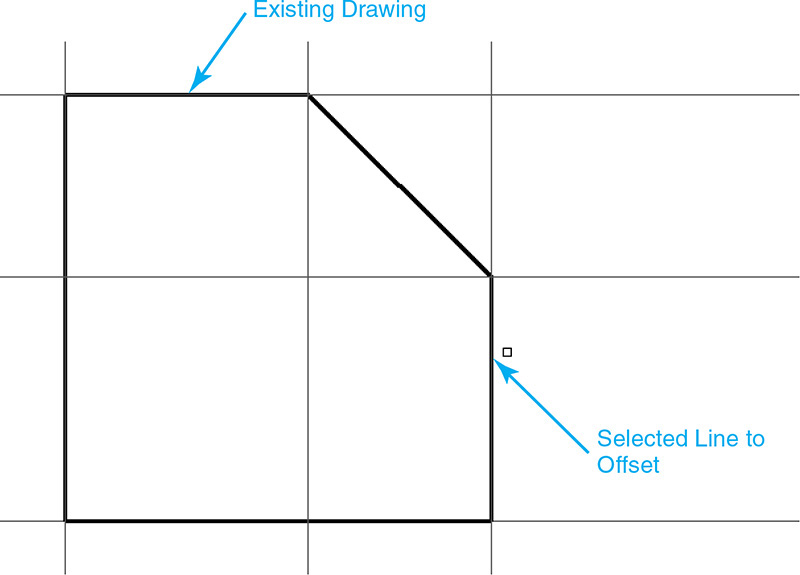
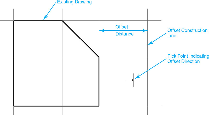
AutoCAD will continue to prompt you to select objects to offset until you press <Enter> so that it is possible to offset multiple objects at a time.
Exercise 5-12 Offsetting Objects with Construction Lines
![]() Continue from Exercise 5-11.
Continue from Exercise 5-11.
![]() Select the XLINE command from the Draw panel.
Select the XLINE command from the Draw panel.
![]() AutoCAD prompts you for an offset distance or through point:
AutoCAD prompts you for an offset distance or through point:
Specify offset distance or ![]() .
.
![]() Type 2<Enter>. AutoCAD prompts you to select the object you want to offset:
Type 2<Enter>. AutoCAD prompts you to select the object you want to offset:
Select a line object:
![]() Select the vertical line, as shown in Figure 5-61A. AutoCAD then prompts you for the side you wish to offset:
Select the vertical line, as shown in Figure 5-61A. AutoCAD then prompts you for the side you wish to offset:
Specify side to offset:
![]() Pick a point on the right side of the object, as shown in Figure 5-61B, to indicate that you want to create a vertical construction line offset on the right-hand side of the line.
Pick a point on the right side of the object, as shown in Figure 5-61B, to indicate that you want to create a vertical construction line offset on the right-hand side of the line.
![]() AutoCAD continues to prompt you to select line objects.
AutoCAD continues to prompt you to select line objects.
![]() Repeat steps 6 and 7 to create a horizontal construction line offset 2 units up from the horizontal line on top of the part, as shown in Figure 5-62.
Repeat steps 6 and 7 to create a horizontal construction line offset 2 units up from the horizontal line on top of the part, as shown in Figure 5-62.
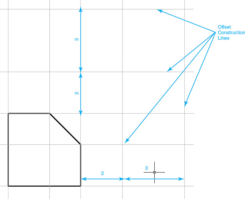
![]() Type <Enter> to end the XLINE command.
Type <Enter> to end the XLINE command.
![]() Repeat steps 2 through 9 to create vertical and horizontal construction lines offset 3 units from the construction lines you just created so your drawing looks like Figure 5-62.
Repeat steps 2 through 9 to create vertical and horizontal construction lines offset 3 units from the construction lines you just created so your drawing looks like Figure 5-62.
![]() Save your drawing.
Save your drawing.
Drawing Angular Construction Lines
Construction lines can be created at an angle either by specifying an angle from the horizontal axis 0° or by referencing an angle from an existing line.
To create a construction line at an angle, start the XLINE command and select the Angle option. By default, AutoCAD prompts you for an angle. Enter the desired angle and locate the construction line by selecting a point. Figure 5-63 shows a 45° construction line located at the Midpoint object snap of an angled line.
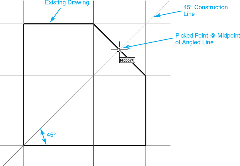
Using the Reference option allows you to select a line object and use its existing angle as a base angle. You can then enter the angle relative to the selected line object. For instance, to create the 45° construction line shown in Figure 5-63 using the Reference option, you would first select the existing angled line and then input the desired angle relative to the selected line. Inputting 90° creates a construction line perpendicular to the angled line, which just so happens to also be 45° from the X-axis.
Exercise 5-13 Drawing Angular Construction Lines
![]() Continue from Exercise 5-12.
Continue from Exercise 5-12.
![]() Start the XLINE command.
Start the XLINE command.
![]() Select the Angle option.
Select the Angle option.
![]() AutoCAD prompts you to enter an angle:
AutoCAD prompts you to enter an angle:
Enter angle of xline (0) or ![]() .
.
![]() Type 45<Enter>. AutoCAD prompts you for a through point:
Type 45<Enter>. AutoCAD prompts you for a through point:
Specify through point:
![]() Select the Midpoint object snap of the angled line as shown in Figure 5-63.
Select the Midpoint object snap of the angled line as shown in Figure 5-63.
![]() Type <Enter> to end the XLINE command.
Type <Enter> to end the XLINE command.
![]() Start the XLINE command again.
Start the XLINE command again.
![]() Select the Offset option.
Select the Offset option.
![]() AutoCAD prompts you to specify an offset distance:
AutoCAD prompts you to specify an offset distance:
Specify offset distance or ![]() .
.
![]() Type .5<Enter>. AutoCAD prompts you to select the object you want to offset:
Type .5<Enter>. AutoCAD prompts you to select the object you want to offset:
Select a line object:
![]() Select the angled construction line you just created. AutoCAD then prompts you for the side you wish to offset:
Select the angled construction line you just created. AutoCAD then prompts you for the side you wish to offset:
Specify side to offset:
![]() Pick a point on the bottom right side of the angled construction line.
Pick a point on the bottom right side of the angled construction line.
![]() Select the angled construction line again. AutoCAD then prompts you for the side you wish to offset:
Select the angled construction line again. AutoCAD then prompts you for the side you wish to offset:
Specify side to offset:
![]() Pick a point on the top left side of the angled construction line.
Pick a point on the top left side of the angled construction line.
![]() Type <Enter> to end the XLINE command.
Type <Enter> to end the XLINE command.
![]() Save your drawing. Your drawing should look like Figure 5-64.
Save your drawing. Your drawing should look like Figure 5-64.

Bisecting an Angle with a Construction Line
You can split an angle into two equal parts by creating a construction line at the bisector of an existing angle using the XLINE command’s Bisect option.
To create a construction line at the bisector of an angle, start the XLINE command and select the Bisect option. AutoCAD prompts you to select a vertex point, an angle start point, and an angle endpoint, as shown in Figure 5-65.
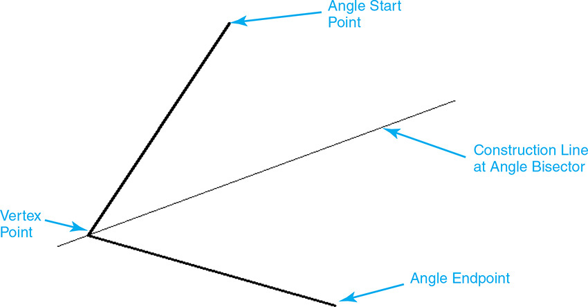
AutoCAD will continue to prompt you to select angle endpoints until you press <Enter> so that it is possible to bisect multiple related angles at the same time.
Exercise 5-14 Creating the Final Drawing Using Construction Lines
![]() Continue from Exercise 5-13.
Continue from Exercise 5-13.
![]() Create the remaining horizontal and vertical construction lines shown in Figure 5-66.
Create the remaining horizontal and vertical construction lines shown in Figure 5-66.
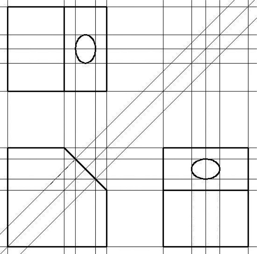
![]() Use the Intersection object snap with the LINE and ELLIPSE commands to create the final drawing shown in Figure 5-66. Hidden lines are not required.
Use the Intersection object snap with the LINE and ELLIPSE commands to create the final drawing shown in Figure 5-66. Hidden lines are not required.
![]() Erase all the construction lines using the ERASE command.
Erase all the construction lines using the ERASE command.
![]() Save your drawing.
Save your drawing.
The RAY Command
It is also possible to create a special construction line known as a ray that is like an Xline except that, unlike an Xline, it extends to infinity in only one direction. Rays are created using the RAY command.
Ray |
|
Ribbon & Panel: |
Home | Draw
|
Command Line: |
RAY |
Command Alias: |
None |

Note
Similar to Xlines, the Zoom Extents tool is unaffected by ray objects. Any rays that exist in a drawing are ignored when zooming to the drawing extents.
After selecting the RAY command, AutoCAD prompts you to pick a start point and a through point to indicate the direction and angle of the ray, as shown in Figure 5-67.
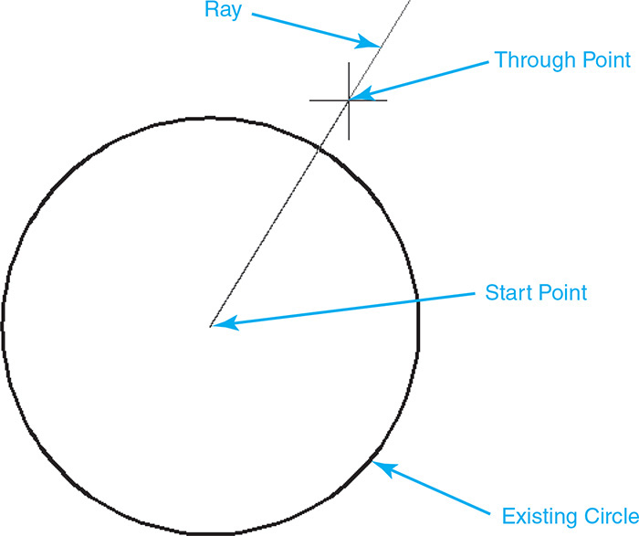
AutoCAD will continue to prompt you for through points until you press <Enter> so that it is possible to create multiple rays that share the same start point.
Tip
It is possible to trim and break Xlines and rays using the advanced editing commands introduced in Chapter 8 so that they can be converted into regular AutoCAD lines. When you trim or break the infinite end of a ray, it changes into a line with two endpoints. You must trim or break both infinite ends of an Xline to change it into a line. Using this approach, you can convert your construction lines directly into the final drawing geometry, thus reducing the time it takes to create a drawing.
Chapter Summary
Mastering the different drawing tools and drafting settings explained in this chapter will increase your drafting exponentially. Being able to locate points quickly and accurately using object snaps is one of the main keys to being more productive. Knowing that a point is located exactly where you intend it makes you a more confident, assured drafter. It’s these qualities that help you to succeed in creating quality CAD drawings in a timely fashion.
Dynamic input allows you to enter information directly at your cursor so that you can focus on your drawing and not have to look back and forth to the command line all of the time. Plus, when Dynamic Input is on, you can use your Tab key to switch between input fields so you can lock in distances and angles. As an added bonus, you can also select command options on the screen by pressing the down arrow key on your keyboard whenever command options are available.
Using construction lines to lay out drawings is an age-old art that not many people know about these days. This is a shame because they can help you become a faster, more accurate drafter. Not only do construction lines allow you to measure once, and then draw twice, or more, they also can speed up the creation of floor plan drawings and even schematics. Using the XLINE command with the Offset option and some basic object snaps, you can lay out a drawing lickety-split. Put the construction lines on a layer that has its No Plot property on, and voilà, you can leave your construction lines on in your drawing but they will not show up on your plots!
For More Details
See page 218 in Chapter 6 for information on setting up a layer so that it does not plot but you can still see information in your drawing.
Chapter Test Questions
Multiple Choice
Circle the correct answer.
1. Most of AutoCAD’s drawing tools can be toggled on and off by:
a. Selecting the buttons on the status bar
b. Using keyboard function keys
c. Typing them at the command line
d. All of the above
2. The rectangular grid display area is determined by the:
a. Units setting
b. Drawing limits
c. Zoom scale factor
d. Size of your computer monitor
3. The two major different snap styles are:
a. Rectangular and polar
b. Rotated and isometric
c. Horizontal and vertical
d. Rows and columns
4. The Ortho Mode drawing tool restricts your cursor movement to:
a. 45° angles
b. 90° angles
c. Horizontal axis
d. Vertical axis
5. Polar tracking works by displaying a dashed line referred to as:
a. Construction line
b. Vector path
c. Alignment path
d. Tracking path
6. Object snaps can be selected by:
a. Clicking on the down arrow menu to the right of the Object Snap button on the status bar
b. Using the right-click shortcut menu
c. Typing them at the command line
d. All of the above
7. Turning an object snap on via the Object Snap tab of the Drafting Settings dialog box is referred to as:
a. Making an object snap permanent
b. Setting a running object snap
c. Creating an object snap override
d. Setting the default object snap
8. An ellipsis (...) next to an object snap AutoSnap marker indicates the object snap is:
a. Implied
b. Delayed
c. Waiting for AutoCAD to regen
d. Deferred
9. Object snap tracking can display alignment paths:
a. At all polar increment angles
b. Horizontally
c. Vertically
d. Horizontally and vertically
10. Construction lines are used for:
a. Laying out your drawing
b. Creating different views using orthographic projection
c. Bisecting angles
d. All of the above
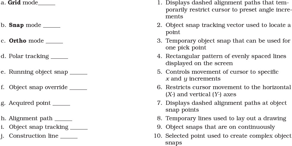
True or False
Circle the correct answer.
1. True or False: It is possible to remove drawing tool buttons temporarily from the status bar.
2. True or False: Drawing tools can be toggled on and off when a command is active.
3. True or False: The grid display controls the cursor movement.
4. True or False: The snap and grid spacing must always be the same.
5. True or False: It is possible to use the Ortho Mode and Polar Tracking drawing tools at the same time.
6. True or False: Polar tracking angles are always measured from the AutoCAD base angle (0°).
7. True or False: Object snaps work only when you are prompted for a point at the command line.
8. True or False: It is possible to snap to the intersection of two lines even if they don’t visually cross but would if they were extended.
9. True or False: You must always pick an acquired point when using object snaps.
10. True or False: Construction lines extend to your drawing limits.
1. Start a new drawing using the acad.dwt template.
2. Draw the figure shown in Figure 5-68 using the appropriate grid and snap settings. Toggle the Object Snap button on and off as needed. The borders around the perimeter and around the screen area are 1/16″. The spacing between the buttons is 1/8″. Do not draw the dimensions.
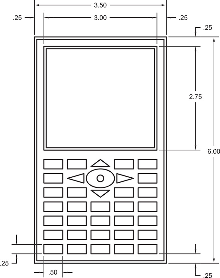
3. Save the drawing as P5-1.
![]() Project 5-2: B-Size Mechanical Border, continued from Chapter 4 [INTERMEDIATE]
Project 5-2: B-Size Mechanical Border, continued from Chapter 4 [INTERMEDIATE]
1. Open the template file Mechanical B-Size.DWT from Chapter 4.
2. Add the line work shown in Figure 5-69. Do not draw dimensions.
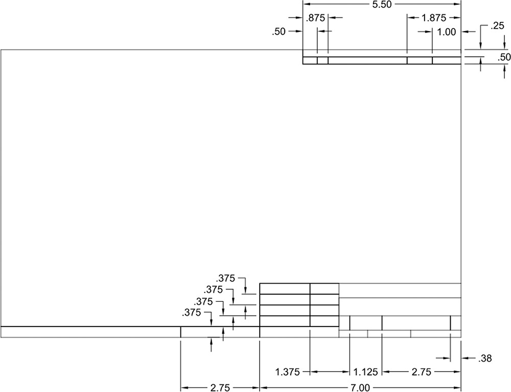
3. Save the drawing template file.
![]() Project 5-3: Architectural D-Size Border, continued from Chapter 4 [ADVANCED]
Project 5-3: Architectural D-Size Border, continued from Chapter 4 [ADVANCED]
1. Open the template file Architectural D-Size.DWT from Chapter 4.
2. Add the line work as shown to the border as shown in Figure 5-70 using construction lines and object snaps to your advantage. Hint: You can use the DIVIDE command to lay out the equally spaced title block lines.
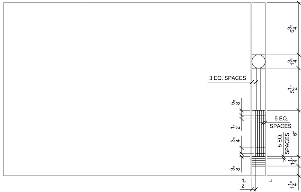
3. Save the drawing template file.
![]() Project 5-4: Electrical Schematic, continued from Chapter 4 [BASIC]
Project 5-4: Electrical Schematic, continued from Chapter 4 [BASIC]
1. Open drawing P4-4 from Chapter 4.
2. Set the Grid Mode and Snap Mode spacing to 0.125.
3. Draw the electrical schematic shown in Figure 5-71. Hint: Use the grid display and Snap mode to draw the lines and object snaps to locate the electrical symbols.
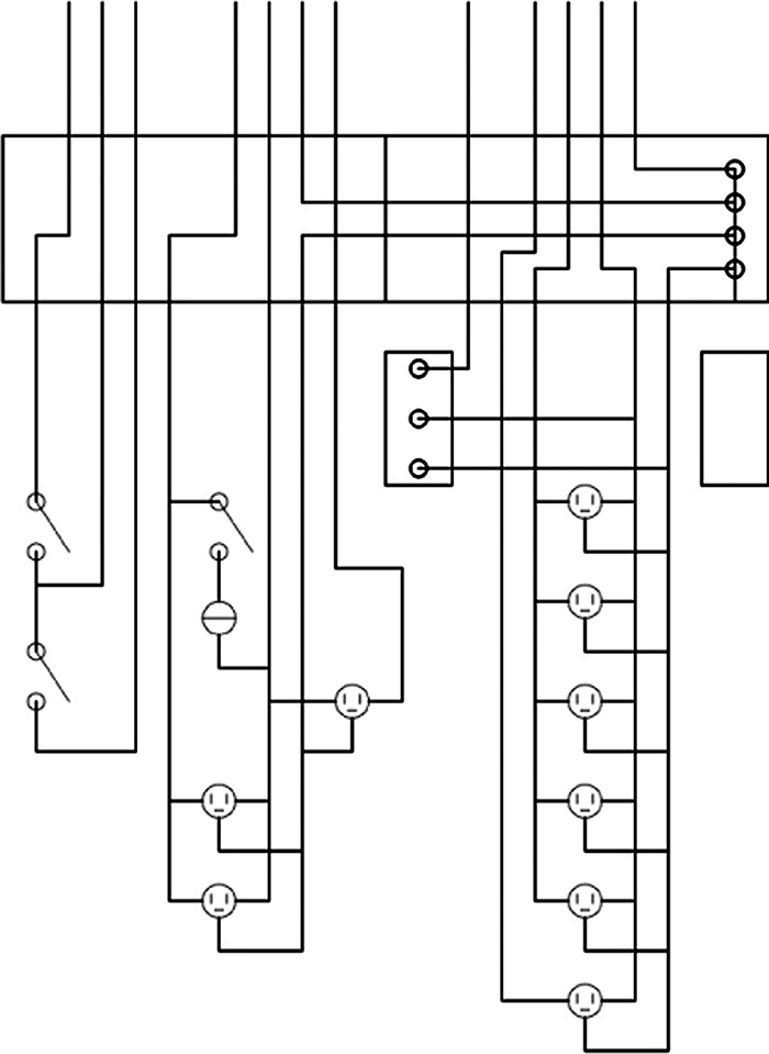
4. Save the drawing as P5-4.
![]() Project 5-5: Residential Architectural Plan, continued from Chapter 4 [ADVANCED]
Project 5-5: Residential Architectural Plan, continued from Chapter 4 [ADVANCED]
1. Open drawing P4-5 from Chapter 4.
2. Draw the additional walls as shown in Figure 5-72. All new walls are 4″ thick. Use the appropriate object snap, Ortho, and polar tracking settings to ensure there are no gaps in the geometry and the walls are at the correct angle and location. Do not draw dimensions or text. Hint: Use the Offset option of the XLINE command to locate walls.
3. Save the drawing as P5-5.