
Chapter 6. Managing Object Properties
• Set layer properties
• Load linetypes
• Modify the properties of drawing objects
• Use DesignCenter and Content Explorer to import layers from other drawings
• Create layer filters and groups
Introduction
Precise, accurate, and clear drawings are a primary goal of any drafter. However, equally important in CAD is creating a well-organized drawing. Chapter 2 gave you a brief overview of object properties and layering. In this chapter, we’ll take a closer look at object properties, how to effectively use layers to organize your drawing, and how to control the look and final output of your drawing.
Common Object Properties
Every object in AutoCAD has five primary properties associated with it: color, linetype, lineweight, transparency, and layer. These properties control how objects are displayed in your drawing and also control how objects are plotted. Color controls the color of an object and can also be used to control the plotted lineweight of an object, linetype controls the line pattern (dashed, dotted, etc.) used to display objects, lineweight (or pen width) controls the width of objects when plotted, and transparency allows you to control the ability to see through objects.
A layer is a collection of color, linetype, and lineweight properties that can be used to organize the objects in your drawing. Layers are the primary way in which drawing information is organized.
layer: A collection of object properties and display settings that are applied to objects.
The concept of layering goes back to the days of manual drafting in which transparent overlays were used to control the content of a blueprint. For example, an architect might create an architectural base print showing the location of walls, doors, windows, and so on. An electrical engineer might then create a transparent overlay showing the location of the electrical equipment, outlets, and such. To create the electrical plan blueprint, you would take the architectural base print, place the electrical overlay on top of it, and run the stack of drawings through the blueprint machine. The resulting print would show the electrical drawing layer over the top of the architectural base drawing.
Layering in AutoCAD works in a similar way. By assigning a layer to an AutoCAD object, you are, in effect, putting those objects on a transparent overlay. You can then turn these layers on and off and control which objects are shown in the drawing.
Layers
When you create a layer, you provide a name for that layer and then assign it a color, linetype, lineweight, and transparency level. Any objects placed on that layer will then, by default, take on the color, linetype, lineweight, and transparency level associated with that layer.
Layer |
|
Ribbon & Panel: |
Home | Layers
|
Menu: |
Format | Layer... |
Command Line: |
LAYER |
Command Alias: |
LA |

AutoCAD comes with a predefined layer, called Layer 0. By default, everything on Layer 0 is drawn with color 7 (white/black), has a continuous linetype, uses the default lineweight (.25 mm or .01 inch) for plotting, and has a transparency level of 0, which is opaque. You can change the color, linetype, lineweight, and transparency settings for Layer 0, but you cannot delete or rename Layer 0.
Layers are created with the LAYER command.
The LAYER Command
When you start the LAYER command, AutoCAD displays the Layer Properties Manager palette (see Figure 6-1). The Layer Properties Manager palette works like all other palettes. It can be docked, hidden, or closed as needed.
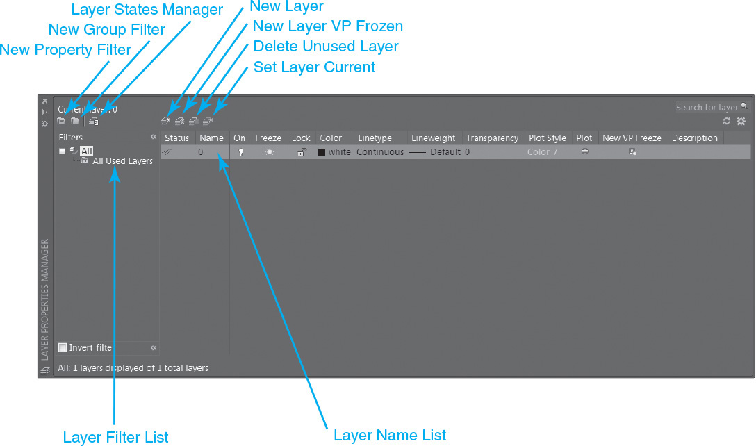
The Layer Properties Manager palette allows you to create and control all aspects of your layers. The palette is divided into two main areas; the layer filters are listed on the left, and the list of layers is shown on the right.
Layer filters allow you to show only layers that match a certain criterion—for example, all the layers that start with the letter “E” or all the layers that are red. The list of layers shows the layers currently defined in your drawing along with their current settings.
Tip
You can collapse the Layer Filter list by clicking on the double arrows on the top and bottom on the right side of the Filters pane.
Layer Name List
The list of layers is divided into columns with each column representing a layer setting. The column headings can be resized by dragging the divider bar between each column. You can also sort the layers by any of the columns by clicking on the column heading. To change a setting for a layer, simply click on the setting. To change the settings for multiple layers, first select the layers by holding down either the <Shift> or <Ctrl> key and selecting the layers, then click on the setting you want to change. The change will be applied to all the selected layers.
Controlling the Column Display
Clicking on a column heading at the top of the layer list in the Layer Properties Manager will toggle the display order of the layers in ascending or descending order using the information in the column header you click on.
You can resize a column by dragging the vertical bar between columns with your mouse, as well as rearrange the display order of the columns by dragging and dropping the column headings to different locations.
Right-clicking on a column heading displays a shortcut menu that allows you to turn different property columns on and off, maximize column widths, or reset everything back to the default. You can also display the Customize Layer Columns dialog box to turn multiple columns off simultaneously and rearrange the column order via the Customize... menu item.
Layer List Right-Click Shortcut Menu
Right-clicking anywhere in the layer list in the Layer Properties Manager displays the shortcut menu shown in Figure 6-2.
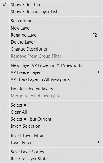
This shortcut menu provides a number of handy, time-saving features and capabilities. Many of the features and capabilities can be found elsewhere in the Layer Properties Manager, but a few are unique to the right-click menu. Some of the things you can do include:
• Turn the Layer Filter list on the left off and on
• Show any layer filters in the Layer Name list on the right so you can manage them as a unit

• Remove viewport property overrides
• Merge multiple layers to a single layer
• Select all/deselect all layers for mass property updates
You can also create and restore layer states, which allow you to manage different saved layer settings. Layer states are discussed in detail later in this chapter.
Layer Names
The layer name is the primary means of identifying a layer. Layer names can have up to 255 characters and can include letters and numbers as well as other special characters, including spaces. Layer names should convey the contents of that layer. Layer names can be based on part numbers, project names, design discipline (civil, architectural, etc.), or any other agreed-upon standard.
Layer Naming Standards
Many companies create layering standards based on their own experience and practices, or they may adopt or adapt a national or industry CAD standard. A good standard will be well documented, showing the appropriate settings and the type of drawing content that belongs on each layer.
Note
AutoCAD layer names can contain all but the following characters: <>/”“:;?*|,=’
The American Institute of Architects (AIA) has published the CAD Layer Guidelines for the building industry that has been adopted by the National CAD Standard organization (http://nationalcadstandard.org). This layering standard describes a method of organizing layers based on a series of prefixes and descriptors that are easy to understand. Each discipline has a prefix; for example, all architectural layers start with A, electrical layers start with E, civil layers start with C, etc. Following the prefix is an abbreviation for the content of that layer, such as A-WALL for architectural walls or E-DEMO for electrical demolition.
The student data files included with this text contain standard drawings for both architectural and mechanical design disciplines. The drawings contain layers set up in accordance with common industry standards.
To access student data files, go to www.pearsondesigncentral.com.
Creating New Layers
To create a new layer, choose the New Layer button on the Layer Properties Manager palette. AutoCAD will create a new layer and automatically call it Layer1. The layer name is highlighted, so to rename the layer, simply type in the new name and press <Enter>. You can press <Enter> again to create another new layer.
You can also create multiple layers by typing the layer names separated by a comma. When you press the comma key, AutoCAD will end the first layer and create a new layer. This method allows you to create multiple layers easily.
![]() Start a new drawing using the acad.dwt drawing template.
Start a new drawing using the acad.dwt drawing template.
![]() Start the LAYER command to display the Layer Properties Manager palette.
Start the LAYER command to display the Layer Properties Manager palette.
![]() Choose the New Layer button. AutoCAD will create a layer called Layer1.
Choose the New Layer button. AutoCAD will create a layer called Layer1.
![]() Type Object<Enter> to rename the new layer.
Type Object<Enter> to rename the new layer.
![]() Press <Enter> to create another new layer.
Press <Enter> to create another new layer.
![]() Type Hidden<Enter> to rename the new layer.
Type Hidden<Enter> to rename the new layer.
![]() Press <Enter> to create another new layer.
Press <Enter> to create another new layer.
![]() Type Center,Dim,Title<Enter> to create three new layers. Notice how every time you type the comma key, AutoCAD creates a new layer. You should now have a total of six layers (including Layer 0) in your drawing.
Type Center,Dim,Title<Enter> to create three new layers. Notice how every time you type the comma key, AutoCAD creates a new layer. You should now have a total of six layers (including Layer 0) in your drawing.
![]() Close the Layer Properties Manager palette.
Close the Layer Properties Manager palette.
![]() Save your drawing as CH6_EXERCISE.
Save your drawing as CH6_EXERCISE.
Setting the Current Layer
To set a layer current, select the layer and choose the Set Current button (or press <Alt>+C). The current layer is the default layer for new drawing objects. Any new object will be placed on the current layer.
On/Off
The On/Off settings control the visibility of the layers in the drawing. Layers that are turned on are displayed, and those that are turned off do not display. However, when a layer is turned off, AutoCAD simply hides the layer from view. Objects can still be selected, modified, and even deleted when their layer is turned off.
Freeze/Thaw
The Freeze/Thaw settings are similar to On/Off. When a layer is frozen, AutoCAD ignores the objects on that layer and does not display them on screen. When a layer is frozen, AutoCAD will completely ignore the objects on that layer until that layer is thawed and the drawing regenerates. Objects on frozen layers cannot be modified until that layer is thawed. For this reason, freezing a layer is generally preferred to turning a layer off.
Exercise 6-2 Freeze and Thaw Versus On and Off
![]() Continue from Exercise 6-1.
Continue from Exercise 6-1.
![]() Draw a line anywhere on the screen. Since Layer 0 is current, the new line is drawn on Layer 0.
Draw a line anywhere on the screen. Since Layer 0 is current, the new line is drawn on Layer 0.
![]() Select the Object layer, and choose the Set Current button. The Object layer is now the current layer.
Select the Object layer, and choose the Set Current button. The Object layer is now the current layer.
![]() Select Layer 0 and choose the sun icon in the Freeze column. The sun icon will change to a snowflake, indicating that the layer is frozen. Close or hide the Layer Properties Manager palette. The line will disappear because Layer 0 is frozen.
Select Layer 0 and choose the sun icon in the Freeze column. The sun icon will change to a snowflake, indicating that the layer is frozen. Close or hide the Layer Properties Manager palette. The line will disappear because Layer 0 is frozen.
![]() Choose the Erase tool from the Modify panel. AutoCAD prompts you to Select objects:.
Choose the Erase tool from the Modify panel. AutoCAD prompts you to Select objects:.
![]() Type All<Enter>. This tells AutoCAD to select all the objects in the drawing. In the command line, AutoCAD responds 0 found. This tells you that AutoCAD ignored the line on the frozen Layer 0. Press <Esc> to end the ERASE command.
Type All<Enter>. This tells AutoCAD to select all the objects in the drawing. In the command line, AutoCAD responds 0 found. This tells you that AutoCAD ignored the line on the frozen Layer 0. Press <Esc> to end the ERASE command.
![]() Start the LAYER command again, and thaw Layer 0 by selecting the snowflake in the Layer 0 Freeze column. Select the lightbulb in the On column to turn off Layer 0. Close or hide the Layer Properties Manager palette.
Start the LAYER command again, and thaw Layer 0 by selecting the snowflake in the Layer 0 Freeze column. Select the lightbulb in the On column to turn off Layer 0. Close or hide the Layer Properties Manager palette.
![]() Choose the Erase tool again, from the Modify panel and type All<Enter> at the Select objects: prompt. In the command line, AutoCAD responds 1 found. This tells you that AutoCAD has selected the line on Layer 0, even though the layer is turned off. Press <Enter> to finish the ERASE command. AutoCAD will erase the line.
Choose the Erase tool again, from the Modify panel and type All<Enter> at the Select objects: prompt. In the command line, AutoCAD responds 1 found. This tells you that AutoCAD has selected the line on Layer 0, even though the layer is turned off. Press <Enter> to finish the ERASE command. AutoCAD will erase the line.
![]() Start the LAYER command and select the lightbulb to turn Layer 0 on. Close the palette to verify that the line was erased.
Start the LAYER command and select the lightbulb to turn Layer 0 on. Close the palette to verify that the line was erased.
You can see that although the On/Off and Freeze/Thaw settings are similar, AutoCAD treats them very differently.
Lock/Unlock
The Lock/Unlock setting controls whether objects on a layer can be modified. Objects on a locked layer can be seen but not modified. To lock a layer, choose the icon in the Lock column for the layer you wish to lock.
Drawing objects that are on a locked layer will appear faded in the drawing to indicate their locked status. In addition, if you move your cursor over an object on a locked layer, a small lock icon appears to further warn you that it cannot be changed. You can control the level of fading used for locked layers via the expanded Layers panel discussed later in this chapter.
Color
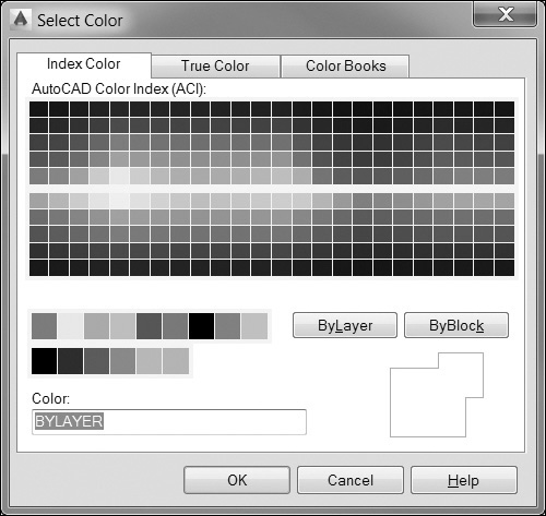
The color property is the default display color for objects on a layer. To assign a color to a layer, pick the color swatch for the layer you wish to change. AutoCAD will display the Select Color dialog box (see Figure 6-3). The Select Color dialog box has three tabs: Index Color, True Color, and Color Books. The three tabs provide different ways to specify colors.
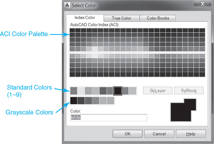
The AutoCAD Color Index (ACI)
The Index Color tab shows the AutoCAD Color Index (ACI), which is the primary way colors are assigned in AutoCAD. The ACI consists of 255 colors (numbered 1–255). Colors 1–9 are called the standard colors and are shown below the main color palette. Grayscale colors are shown below the standard colors.
standard colors: Colors 1–9 of the AutoCAD Color Index.
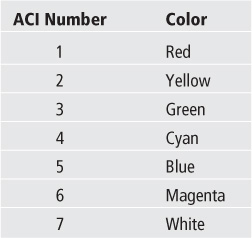
Colors 1–7 have names assigned to them. The names are shown in the following table:
The remaining colors are shown in the large color palette (see Figure 6-3). As you drag your cursor over the various color patches, AutoCAD will display the color number as well as the red, green, and blue components of each color. To select a color, simply click on a color patch. AutoCAD will display the color name or number in the Color: box. AutoCAD will also show you a preview of the selected color. If you know the color name or number you wish to use, you can simply type it into the Color: text area.
Note
Color 7 shows up as black on a white background and white on a black background.
True Color
The True Color tab allows you to select colors based on either the RGB (Red, Green, Blue) or HSL (Hue, Saturation, Luminance) color model (see Figure 6-4). You can select the color model you wish to use from the Color model: drop-down list.
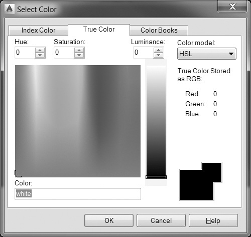
The HSL color model allows you to control color properties in three ways. The Hue: setting refers to a color in the visible spectrum, from 0 to 360. On the color chart, a Hue: setting goes from 0 on the left of the chart to 360 on the right.
The Saturation: setting refers to the purity of that color on a scale of 0 to 100%. On the color chart, saturation values go from 0 (gray) at the bottom of the chart to 100 (the pure color) at the top of the chart.
The Luminance: setting represents the brightness of the color on a scale of 0 to 100%. The Luminance: setting is represented in the bar to the right of the color chart. A luminance value of 0 (the bottom of the bar) gives you black, a value of 100 (the top of the bar) gives you white, and a setting of 50 represents the brightest value of the color.
When you select a color on the chart, its color is displayed in the preview area, and its RGB color values are displayed in both the color box and below the Color model: drop-down list.
The RGB color model (see Figure 6-5) allows you to mix colors based on the red, green, and blue components. An RGB number is a set of three numbers representing the red, green, and blue color components, respectively. Each component can have a value from 0 to 255 with 0 representing black, or no color, and 255 representing the pure color component. For example, a color setting of 255,0,0 represents red, 0,255,0 represents green, and 0,0,255 represents blue. White has an RGB value of 255,255,255, and black has an RGB value of 0,0,0.
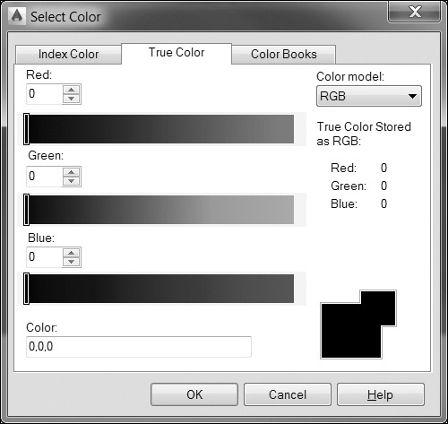
When you select the RGB color model, AutoCAD gives you three sliders to control the RGB components. You can type in a value, pick a point on each slider, or drag the indicator to a location on the slider to specify the value for each component.
Color Books
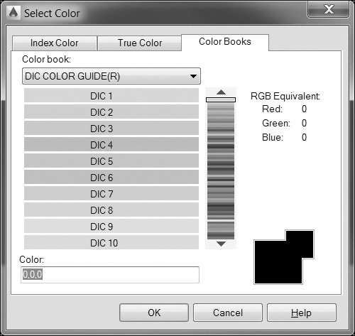
The Color Books tab allows you to select colors based on various color matching standards, such as Pantone, DIC, or RAL. When you select the Color Books tab, AutoCAD provides you with a list of available color books and a list of colors in each book (see Figure 6-6). Once you select a color, AutoCAD displays its RGB color value on the right side of the dialog box and shows the color in the preview area.
Exercise 6-3 Setting Layer Colors
![]() Continue from Exercise 6-2.
Continue from Exercise 6-2.
![]() Start the LAYER command.
Start the LAYER command.
![]() Choose the color box in the Color column of the Object layer. The Select Color dialog box will appear.
Choose the color box in the Color column of the Object layer. The Select Color dialog box will appear.
![]() In the Index Color tab, select the color red (color index 1), and choose OK to close the dialog box.
In the Index Color tab, select the color red (color index 1), and choose OK to close the dialog box.
![]() Continue setting colors for the layers as follows:
Continue setting colors for the layers as follows:
Center—Blue (Color 5)
Dim—Color 8
Hidden—Green (Color 3)
Title—White (Color 7)
![]() Close the Layer Properties Manager palette.
Close the Layer Properties Manager palette.
![]() Save your drawing.
Save your drawing.
Linetypes
Linetype refers to the pattern (continuous, dashed, dotted, etc.) of a line. Linetypes are generally a series of lines, spaces, dots, and symbols (circles, squares, text, etc.) at preset intervals. Linetypes are used to designate a particular type of object (fence line, railroad tracks, hot water line, etc.) or a feature of an object (the hidden edge of an object, centerline of a circle or arc, etc.).
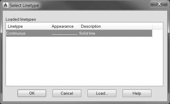
To assign a linetype to a layer, choose the Linetype setting for the layer you want to change. The Select Linetype dialog box will appear (see Figure 6-7). The Select Linetype dialog box shows all the currently available linetypes in your drawing. Before you can use a linetype, it must first be loaded into your drawing.
Standard Linetypes
AutoCAD comes with a large selection of standard linetypes. These linetype definitions are stored in linetype files. AutoCAD comes with two standard linetype files, ACAD.LIN and ACADISO.LIN. The standard AutoCAD linetypes are shown in the following table. You can also create and modify linetypes to meet your needs.
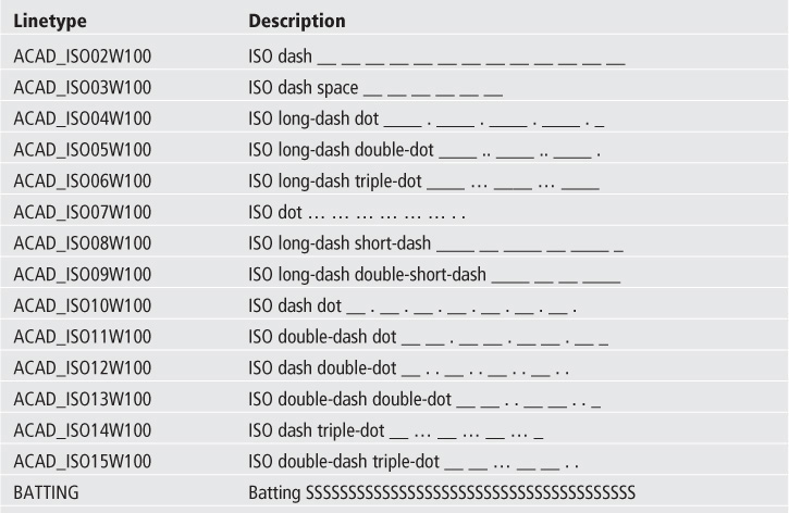
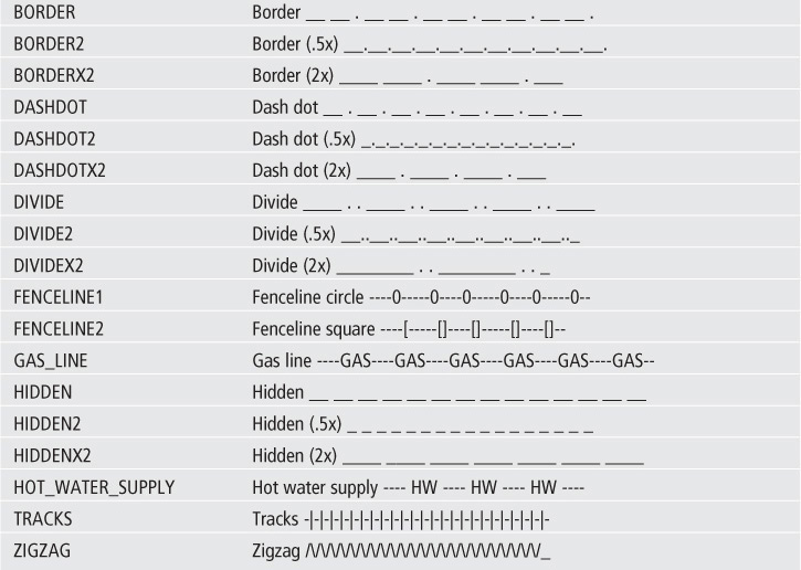
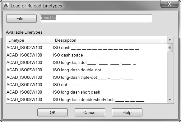
AutoCAD’s linetype files, along with the ability to create your own linetypes, mean there is a potentially unlimited number of linetypes available. In any given drawing, you will use only a limited number of these linetypes so linetypes are loaded into your drawing on an as-needed basis. To load linetypes into your drawing, choose the Load... button in the Select Linetype dialog box. This will display the Load or Reload Linetypes dialog box (see Figure 6-8).
Note
The ACADISO.LIN file contains all the linetypes included in the ACAD.LIN file but also contains linetypes that support the Japanese Industrial Standard (JIS Z 8312).
The Load or Reload Linetypes dialog box shows you the current linetype file and displays all the linetypes defined within that file. You can specify a different file by choosing the File... button and selecting the linetype file you wish to use.
To load a linetype, select a linetype from the list of available linetypes and choose OK. You can select multiple linetypes by holding down either the <Shift> or the <Ctrl> key while selecting linetypes. Once you choose OK, you are returned to the Select Linetype dialog box.
Once the linetypes are loaded into your drawing, you can assign a linetype to a layer by selecting a linetype in the Select Linetype dialog box and choosing OK. The selected linetype will be assigned to the layer.
Note
Some linetypes have multiple versions of each linetype defined in the .LIN file. Generally, these linetypes have lines and spaces that are either half or twice the size of the original. For example, in addition to the CENTER linetype, there are also CENTER2 and CENTERX2 linetypes. The CENTER2 linetype has lines and spaces that are half (.5x) the size of the CENTER linetype. The CENTERX2 linetype has lines and spaces that are twice (2x) the size of the CENTER linetype.
Exercise 6-4 Setting the Layer Linetype
![]() Continue from Exercise 6-3.
Continue from Exercise 6-3.
![]() Start the LAYER command.
Start the LAYER command.
![]() Choose Continuous in the Linetype column of layer Center. This displays the Select Linetype dialog box.
Choose Continuous in the Linetype column of layer Center. This displays the Select Linetype dialog box.
![]() Choose the Load... button. This displays the Load or Reload Linetypes dialog box.
Choose the Load... button. This displays the Load or Reload Linetypes dialog box.
![]() Hold down the <Ctrl> key, and select the CENTER and HIDDEN linetypes. Choose OK to return to the Select Linetype dialog box. The linetypes have now been loaded into your drawing.
Hold down the <Ctrl> key, and select the CENTER and HIDDEN linetypes. Choose OK to return to the Select Linetype dialog box. The linetypes have now been loaded into your drawing.
![]() Choose the CENTER linetype, and choose OK to assign the linetype to layer Center.
Choose the CENTER linetype, and choose OK to assign the linetype to layer Center.
![]() Choose Continuous in the Linetype column of layer Hidden. This displays the Select Linetype dialog box.
Choose Continuous in the Linetype column of layer Hidden. This displays the Select Linetype dialog box.
![]() Choose the HIDDEN linetype, and choose OK to assign the linetype to layer Hidden.
Choose the HIDDEN linetype, and choose OK to assign the linetype to layer Hidden.
![]() Choose OK to close the Layer Properties Manager palette.
Choose OK to close the Layer Properties Manager palette.
![]() Save your drawing.
Save your drawing.
Tip
It is possible to load and manage linetypes without using the Layer Properties Manager palette via the Linetype Manager dialog box discussed later in the section “Linetype Control and Management” on page 237.
Lineweights
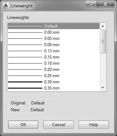
Lineweight refers to the printed width of a line. The ANSI (American National Standards Institute) standard Y14.2 recommends using two lineweights (thick and thin) to differentiate contrasting lines. The actual values you use will depend on your particular CAD standards. AutoCAD’s default lineweight is .25 mm (.010″).
Note
Before the lineweight setting was introduced in AutoCAD, pen tables were used to map AutoCAD colors to plotted lineweights. For example, all red objects are plotted with a .35 mm pen, yellow objects with a .15 mm pen, etc. AutoCAD still supports pen tables and gives you a number of options for creating and managing them.
To assign a lineweight to a layer, choose the value in the Lineweight column for that layer. This will bring up the Lineweight dialog box (see Figure 6-9). Select the lineweight you wish to use and choose OK to assign the lineweight to the layer.
Exercise 6-5 Setting the Layer Lineweight
![]() Continue from Exercise 6-4 and start the LAYER command.
Continue from Exercise 6-4 and start the LAYER command.
![]() Choose Default in the Lineweight column of layer Object. This displays the Lineweight dialog box.
Choose Default in the Lineweight column of layer Object. This displays the Lineweight dialog box.
![]() Choose 0.60 mm from the list and choose OK. This sets the lineweight for layer Object.
Choose 0.60 mm from the list and choose OK. This sets the lineweight for layer Object.
![]() Hold down the <Ctrl> key, and select the Center, Hidden, and Dim layer names. The layers will highlight.
Hold down the <Ctrl> key, and select the Center, Hidden, and Dim layer names. The layers will highlight.
![]() Choose the Default icon in the Lineweight column of the Center layer, and choose 0.30 mm from the lineweight list. Choose OK to set the lineweight for all the selected layers.
Choose the Default icon in the Lineweight column of the Center layer, and choose 0.30 mm from the lineweight list. Choose OK to set the lineweight for all the selected layers.
![]() Choose OK to close the Layer Properties Manager palette.
Choose OK to close the Layer Properties Manager palette.
![]() Save your drawing.
Save your drawing.
Note
The list of available lineweights is fixed in AutoCAD. You can, however, adjust the actual value of the plotted lineweight using the Plot Style Manager.
Lineweight display can be turned on and off via the Show/Hide Lineweight button on the AutoCAD status bar. The lineweight thickness shown on your screen is only a graphical approximation and does not accurately reflect the plotted lineweight, as noted earlier. It is possible to adjust the display scale, change the default lineweight, and switch from metric units to inches using the Lineweight Settings dialog box shown later in the section “Lineweight Control and Management” on page 237.
Transparency
As first mentioned in Chapter 1, it is possible to make objects transparent in AutoCAD so that you can see through them and view objects below. Transparency can be assigned by layer or individually for an object, just like the color, linetype, and lineweight properties. Using the layer method to control transparency is typically preferred because it gives you the most control over your drawing information.
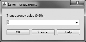
Transparency is controlled by specifying a value from 0 to 90, where 0 is opaque and 90 is almost completely translucent. The default transparency value for layers and objects is 0. To change the transparency level for all objects on a layer, click in the Transparency column for the layer you want to change in the Layer Properties Manager palette. The Layer Transparency dialog box shown in Figure 6-10 is displayed where you can either enter a new value manually or select a new value in increments of 10 from the drop-down list.
Note
You can turn off transparency when plotting. The Plot and Page Setup dialogs both include a check box for transparency. Be forewarned, though, that when the Transparency option is enabled, AutoCAD rasterizes the entire drawing for plotting so that plot times will increase exponentially.
Plot Style
The Plot Style setting is used when a drawing is set up to use named plot styles. This is a drawing setting that allows you to use unique custom styles to control the plotted pen weight and appearance of objects when they are plotted. Typically, most drawings are set up by default to use color-dependent plot styles, which cannot be changed in the Layer Properties Manager because they are hardwired to the layer’s color assignment.
For More Details
See page 620 in Chapter 15 for more on using plot styles and the Plot Style Manager.
Plot/Noplot
The Plot/Noplot setting controls whether the contents of a layer will appear on a print of the drawing. This setting allows you to create objects in AutoCAD that will appear only in the drawing file, but not on any of the printed output of the drawing. For example, you may wish to create layers for construction lines, internal design notes, or drafting markups. To toggle the Plot/Noplot setting, choose the Plot setting for that layer. Plotting layers will show a printer icon, and nonplotting layers will have a red line through the printer icon.
New VP Freeze
The New VP Freeze setting freezes the selected layer in any new viewports that are subsequently created in a paper space layout. It is possible to control layer visibility per individual viewport in paper space so that you can set up multiple views in one or more layouts that each show different drawing information.
Note
In order to take advantage of viewport overrides, all drawing objects should be created using the ByLayer property discussed later in this chapter in the “Hard-Coded Versus Soft-Coded Properties” section.
In fact, if you are in a paper space layout and start the LAYER command to display the Layers Properties Manager palette, four columns are added to the right of the New VP Freeze column so that you can control all aspects of a layer’s appearance per viewport using the following viewport overrides:
• VP Color Controls the layer color per viewport
• VP Linetype Controls the layer linetype per viewport
• VP Lineweight Controls the layer lineweight per viewport
• VP Plot Style Controls the layer plot style per viewport
For More Details
See page 588 in Chapter 14 for more information on controlling layer properties per paper space viewport using viewport overrides.
Description
The Description setting allows you to add a brief description of the layer. For example, a layer named A-Wall might have a description of “Architectural walls.” To change the description of a layer, select the layer and then single-click inside the Description field. A flashing text cursor will appear, allowing you to change the layer description.
Deleting a Layer
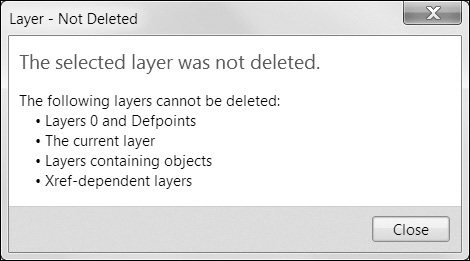
To delete a layer from your drawing, select the layer(s) from the layer list and choose the Delete Layer button (or choose <Alt>+D). A layer can be deleted only if it is not used in the drawing or if it is not the current layer. If the layer is not used and is not the current layer, AutoCAD will delete the layer. You can use Undo in the Quick Access toolbar to bring back a deleted layer.
If the layer is used in the drawing, or if it is the current layer, AutoCAD will display an error message (see Figure 6-11).
Note
Sometimes a layer may appear empty or unused in your drawing but you are still unable to delete it. Many times this is due to a layer being used in a block or xref. Even though the layer is currently empty, you cannot delete that layer until the block or xref that uses that layer is also deleted.
Layer Settings
Selecting the Setting button in the Layer Properties Manager displays the Layer Settings dialog box shown in Figure 6-12.
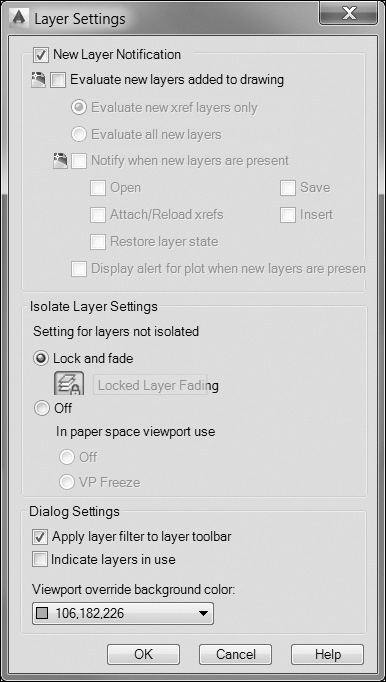
The Layer Settings dialog box allows you to control the New Layer Notification feature, apply a layer filter to the Layer toolbar so only filtered layers are displayed, and change the background color for viewport overrides, introduced earlier in the chapter.
The New Layer Notification feature prevents new layers from being added to your drawing without your knowledge by creating a list of what are referred to as reconciled layers, using all the existing layer names the first time you save or plot a drawing.
When the Evaluate new layers added to drawing check box is turned on, a Notification icon is displayed in the status tray at the bottom right of the AutoCAD window when a new layer is added to your drawing that does not match the reconciled layer list. Clicking on the Notification icon will display a list of unreconciled layers in the Layer Properties Manager.
You can choose to evaluate only new layers that are added when an external refererence (xref) drawing is attached or to evaluate all new layers that are added to your drawing, regardless of the source.
You can control when layer evaluation and notification is performed when the Notify when new layers are present check box is selected. Layer evaluation can be performed when the Open, Save, Attach/Reload xrefs, Insert, and Restore layer state options are selected.
The Display alert for plot when new layers are present check box allows you to control separately whether layer evaluation and notification is performed when a plot is created.
The Isolate Layer Settings area allows you to control how layers are isolated using the LAYISO command. The LAYISO command allows you to work on only a selected group of layers. Nonselected layers are either locked and faded or turned off. The Isolate Layer Settings area of the Layer Settings dialog box allows you to select which method to use as well as set the amount of fading that occurs.
Using Layers
In AutoCAD, the current layer is shown in the Layer Control drop-down list in the Layers panel (see Figure 6-13). This drop-down list shows you the current settings for your layers. You can change the active layer by selecting a new layer from the drop-down list. You can also toggle layer settings from this list by selecting the icon for that setting. For example, to freeze a layer, choose the drop-down list and select the Freeze/Thaw icon next to the layer you wish to freeze. The icon will change from a sun to a snowflake, indicating the layer has been frozen. You can use this list to toggle the On/Off, Freeze/Thaw, and Lock/Unlock settings.
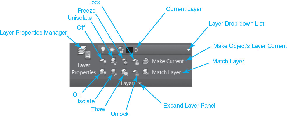
The Layers panel has some additional buttons. The Make Object’s Layer Current button allows you to select an object in your drawing and have that object’s layer become the current drawing layer. The other buttons are as follows:
• Match Layer Changes the layer of one or more selected objects to match the destination layer of another object that you select in the drawing
• Lock Locks the layer of a selected object
• Unlock Unlocks the layer of a selected object
• Freeze Freezes the layer of a selected object
• Thaw Thaws the layer of a selected object
• Isolate Hides or locks all the objects in the drawing except for the ones you select
• Unisolate Undoes the Isolate tool
• On Turns on the layer of a selected object
• Off Turns off the layer of a selected object
Exercise 6-6 Using the Layers Panel
![]() Continue from Exercise 6-5.
Continue from Exercise 6-5.
![]() In the Layer Control drop-down list, choose Hidden to set that layer current.
In the Layer Control drop-down list, choose Hidden to set that layer current.
![]() Draw a line that is approximately 3 inches long anywhere on the screen. The line will have the color and linetype of layer Hidden.
Draw a line that is approximately 3 inches long anywhere on the screen. The line will have the color and linetype of layer Hidden.
![]() In the Layer Control drop-down list, set the layer Object current. Draw another roughly 3-inch line anywhere in the drawing. The line will have the color and linetype of the Object layer.
In the Layer Control drop-down list, set the layer Object current. Draw another roughly 3-inch line anywhere in the drawing. The line will have the color and linetype of the Object layer.
![]() Turn on lineweight display by typing LWDISPLAY<Enter> and setting it to On.
Turn on lineweight display by typing LWDISPLAY<Enter> and setting it to On.
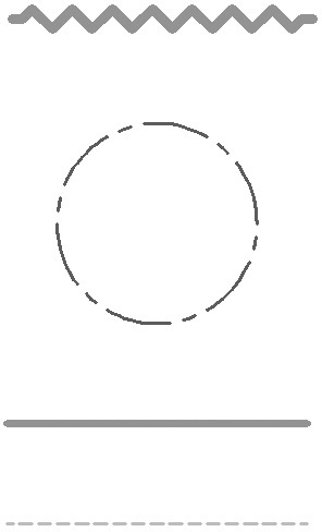
![]() Set the Center layer current and draw a circle with a 1-inch radius anywhere on the drawing. The line will have the color and linetype of the Center layer. Your drawing should resemble Figure 6-14.
Set the Center layer current and draw a circle with a 1-inch radius anywhere on the drawing. The line will have the color and linetype of the Center layer. Your drawing should resemble Figure 6-14.
![]() Save your drawing.
Save your drawing.
Linetype Scale
The linetypes displayed in the drawing are defined by the linetype definitions that were loaded from the .LIN file. The linetype is defined by the length of the dashes and spaces in the line and uses the drawing units to define those lengths. For example, say a linetype is defined as a line segment .5 unit long followed by a space of .25 unit and then repeated. When drawn in a metric drawing using mm as the base unit, that linetype would be a series of .5 mm lines and .25 mm spaces.
Linetype Scale |
|
Ribbon & Panel: |
Home | Properties |
Menu: |
Format | Linetype |
Command Line: |
LTSCALE |
Command Alias: |
LTS |
The LTSCALE command allows you to set a global scaling factor for all linetypes. The LTSCALE command prompts you for a new linetype scale factor. The linetypes of all objects are multiplied by this scaling factor. For example, an LTSCALE setting of 2 would make each line segment and space twice its defined size. An LTSCALE setting of .5 would make each linetype half its defined size.
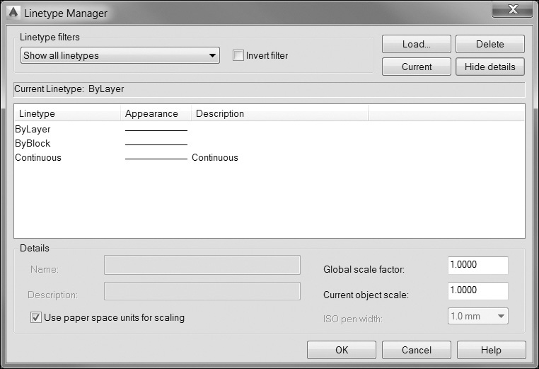
It is also possible to set the LTSCALE via the Linetype Manager dialog box shown in Figure 6-19, although it is not obvious where it is set. In order to access any of the linetype scaling options, you must select the Show details button on the top right to display the details at the bottom of the dialog box (see Figure 6-20). The Global scale factor: setting updates the LTSCALE. See the “Linetype Control and Management” section later in this chapter for more information about the Linetype Manager dialog box.
Exercise 6-7 Setting the LTSCALE
![]() Continue from Exercise 6-6.
Continue from Exercise 6-6.
![]() Type LTSCALE<Enter>. AutoCAD prompts you to Enter new linetype scale factor<1.0000>:.
Type LTSCALE<Enter>. AutoCAD prompts you to Enter new linetype scale factor<1.0000>:.
![]() Type .5<Enter> to set the linetype scale. The linetype pattern of the objects on the Hidden and Center layers will scale down by 50%.
Type .5<Enter> to set the linetype scale. The linetype pattern of the objects on the Hidden and Center layers will scale down by 50%.
![]() Save your drawing.
Save your drawing.
Note
The MSLTSCALE system variable allows you to scale linetype definitions by the current annotation scale. Setting MSLTSCALE to 1 turns on automatic linetype scaling. It is on by default.
Hard-Coded Versus Soft-Coded Properties
By default, when an object is created in a drawing, it takes on the color, linetype, lineweight, and transparency settings of the current layer. When this happens, its properties are defined as Bylayer. This means that the color, linetype, lineweight, and transparency of an object are defined by the layer on which the object resides. For example, say your drawing has a layer called Object, which is red, and has a continuous linetype and a lineweight of .6 mm. If you draw a line on that layer, by default it would show up as a red, continuous, .6 mm-wide line. This line is considered to have soft-coded properties in that its properties are defined indirectly by the layer on which it resides. If you were to change the layer color to blue, the object would update to reflect the changes to its layer.
It is possible to override these soft-coded properties and define the color, linetype, lineweight, and transparency directly. These are called hard-coded properties because the properties are assigned directly to the object, regardless of which layer it resides on.
Using the hard-coded, or override, method of assigning properties directly to objects should typically be avoided because it makes it much more difficult to manage the appearance of objects in your drawings. If a change needs to be made, you must comb through all of the objects in a drawing and update them individually. Using the Bylayer approach allows you to make changes in one place, the Layer Properties Manager, and update all of the objects on a layer simultaneously. For this reason, many organizations have strict rules against using hard-coded properties.
The SETBYLAYER command allows you to quickly update the color, linetype, lineweight, and transparency of objects to the ByLayer property.
Setting the Default Object Properties
The current settings for the color, linetype, lineweight, and transparency properties are shown in the Properties panel (see Figure 6-15). AutoCAD applies these current property settings to all new objects. By default, these are all set to ByLayer.
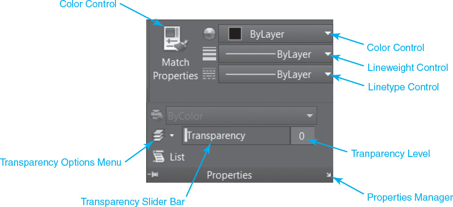
To change the current setting, select the setting from its respective drop-down list. Any new objects you create will take on these properties.
Tip
Using the Properties panel, you can dynamically preview changes to an object before applying the change. Selected objects change dynamically as you pass the cursor over each property in the list.
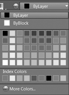
Color Control and Management
In the Color Control drop-down list, you see a list consisting of ByLayer, ByBlock, a color list, and a MoreColors... item (see Figure 6-16). The More Colors... item starts the COLOR command and displays the Select Color dialog box (see Figure 6-17). This is the same dialog box used to select colors within the LAYER command. To set the current drawing color, select the color from the Color Control drop-down list or choose the More Colors... item and select the color from the Select Color dialog box.
Color |
|
Ribbon & Panel: |
Home | Properties |
|
|
Menu: |
Format | Color... |
Command Line: |
COLOR |
Command Alias: |
COL |
Linetype Control and Management
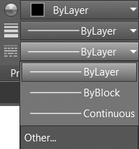
In the Linetype Control drop-down list (see Figure 6-18), you are shown a list of all the currently loaded linetypes in the drawing as well as the ByLayer and ByBlock settings and an Other... item. The Other... item starts the LINETYPE command, which displays the Linetype Manager dialog box (see Figure 6-19).
Linetype |
|
Ribbon & Panel: |
Home | Properties |
|
|
Menu: |
Format | Linetype... |
Command Line: |
LINETYPE |
Command Alias: |
LT |
Note
In the LAYER command, the Select Color dialog box has the ByLayer and ByBlock buttons disabled. In the COLOR command, these buttons are enabled. These choices are also available in the Color Control drop-down list in the Properties panel. The ByLayer setting resets the color to its layer-defined, soft-coded color property. The ByBlock setting creates everything using color 7 until the objects are grouped into a block.
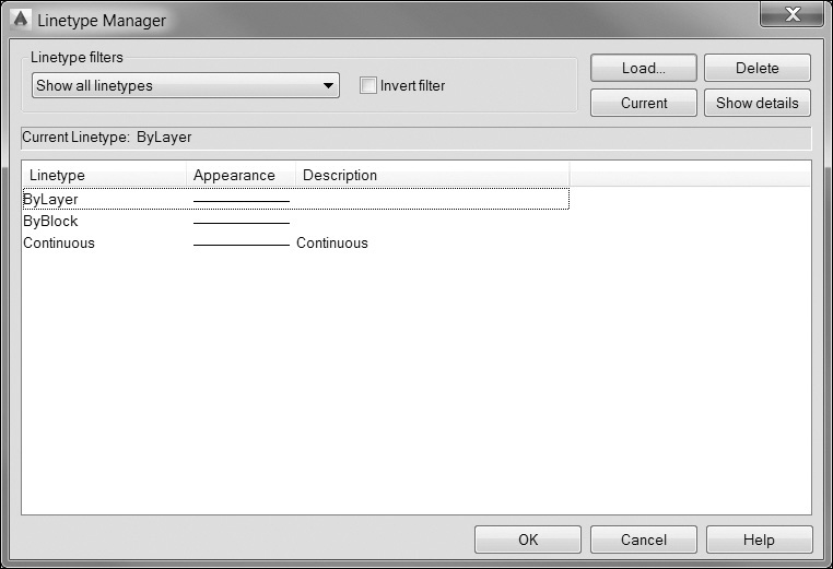
The Linetype Manager dialog box is similar to the Select Linetype dialog box within the LAYER command (see Figure 6-7) but with a few added features. The Linetype Manager dialog box not only shows you all the currently loaded linetypes but also includes a filter that allows you to show all the linetypes loaded into the drawing, only the linetypes currently in use, or all that are used in any xref files. You can also invert the filter to show you only linetypes that are not in use or not used in xref files.
For More Details
Xref stands for externally referenced files. Xrefs allow you to display the contents of other drawing files overlaid onto your current drawing. Chapter 17 describes how to use and manage xrefs.
The Load... button displays the Load or Reload Linetypes dialog box. This is the same dialog box used within the LAYER command and allows you to load linetypes from .LIN files.
The Delete button allows you to delete unused linetypes from the drawing. Only linetypes that are not currently used can be deleted.
The Show details button displays an additional area of the global box that shows additional information about each linetype and also allows you to set the linetype scale for all objects (LTSCALE), set the current linetype scale (CELTSCALE), and control whether linetypes are scaled in paper space using the current viewport scale (PSLTSCALE) (see Figure 6-20).
For More Details
See page 600 in Chapter 14 for more information about paper space linetype scaling.
Lineweight Control and Management
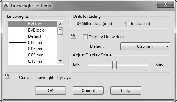
The Lineweight Control drop-down list shows you a list of all available lineweights. The lineweights are set to millimeter (mm) units by default. You can change the units and control other aspects of lineweight setting by selecting Lineweight Settings... from the bottom of the Lineweight drop-down list or by using the LINEWEIGHT command.
Lineweight |
|
Ribbon & Panel: |
Home | Properties |
|
|
Pull-down Menu: |
Format | Lineweight... |
Command Line: |
LINEWEIGHT or LWEIGHT |
Command Alias: |
LW |
Either method displays the Lineweight Settings dialog box (see Figure 6-21), which includes controls to turn the lineweight display on and off, set the default lineweight, and switch the units from millimeters to inches. The Adjust Display Scale slider allows you to control the relative thickness of the lineweight display on your screen. It does not affect the plotted width of the lineweight.
Transparency Control and Management
Just like the other object property overrides discussed thus far, it is best to use the ByLayer option to control transparency for maximum control of your drawing. Although you can assign transparency directly to objects, it is not advised. In fact, the default setting is ByLayer on the Transparency options menu located on the Properties panel of the Home tab of the ribbon, as shown in Figure 6-22.
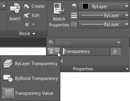
Moving the Transparency slider bar to the right or entering a value between 1 and 90 in the corresponding number box turns off the ByLayer method and assigns the specified transparency setting directly to any new objects created in the drawing.
The ByBlock method of assigning transparency is an advanced technique that is used with blocks and can be ignored for now. The ByBlock method of assigning object properties is discussed in Chapter 16.
Tip
You can also control transparency using the CETRANSPARENCY system variable. It has the following settings:
ByLayer: Transparency value determined by layer
ByBlock: Transparency value determined by block
0: Fully opaque
1–90: Transparency value defined as a percentage
Exercise 6-8 Setting Hard-Coded Properties
![]() Continue from Exercise 6-7.
Continue from Exercise 6-7.
![]() From the Layer Control drop-down list, set the Object layer current.
From the Layer Control drop-down list, set the Object layer current.
![]() From the Color Control drop-down list, set the current color to Magenta (color 6).
From the Color Control drop-down list, set the current color to Magenta (color 6).
![]() From the Linetype Control drop-down list, choose Other... to display the Linetype Manager dialog box.
From the Linetype Control drop-down list, choose Other... to display the Linetype Manager dialog box.
![]() Load the ZIGZAG linetype from the acad.lin linetype file and set it to be the current linetype. Choose OK to close the Linetype Manager dialog box.
Load the ZIGZAG linetype from the acad.lin linetype file and set it to be the current linetype. Choose OK to close the Linetype Manager dialog box.
![]() From the Lineweight Control drop-down list, set the current lineweight to 0.80 mm.
From the Lineweight Control drop-down list, set the current lineweight to 0.80 mm.
![]() Draw a line approximately 3 inches long above the circle. The new line will have the current color, linetype, and lineweight settings even though the Object layer has different properties. Your drawing should resemble Figure 6-23.
Draw a line approximately 3 inches long above the circle. The new line will have the current color, linetype, and lineweight settings even though the Object layer has different properties. Your drawing should resemble Figure 6-23.
![]() Save your drawing.
Save your drawing.
Changing the Properties of Objects
There are a number of ways to change the properties of existing objects. In Chapter 2, you were introduced to the Quick Properties palette, which provides an easy way to change the properties of any object.
Properties |
|
Ribbon & Panel: |
View | Palettes
|
Menu: |
Modify | Properties |
Command Line: |
PROPERTIES |
Command Alias: |
PR |

Tip
Double-clicking on most objects will automatically display the Quick Properties palette.
The Properties Palette
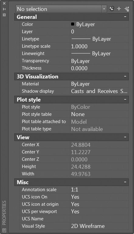
As stated at the beginning of the chapter, there are five properties that are common to all objects: layer, color, linetype, lineweight, and transparency. These are shown in the General area of the Properties palette (see Figure 6-24). You can change any of the properties by selecting the value from the palette and choosing a new value. Using the Properties palette, you can dynamically preview changes to an object before applying the change. Selected objects change dynamically as you pass the cursor over each property in the list.
Tip
You can turn the dynamic preview feature on and off via the PROPERTYPREVIEW system variable. Setting PROPERTYPREVIEW to Off disables the dynamic preview. Setting PROPERTYPREVIEW to On turns it back on.
Note
The Thickness property shown in the Properties palette is used to assign a three-dimensional “thickness” to AutoCAD objects. Although it is a common property of all objects, it is rarely used in 2D drawings and is beyond the scope of this text.
The Linetype scale option in the Properties palette allows you to change the linetype scale of individual objects. This object linetype scale factor is applied in addition to the global linetype scale set by the LTSCALE command. For example, a line created with an object linetype of 2 in a drawing with LTSCALE set to 0.5 would appear the same as a line created with an object linetype of 1 in a drawing with LTSCALE set to 1.
The Hyperlink property allows you to assign an Internet URL or email address to an object.
For More Details
See the online AutoCAD documentation for more on using the Thickness setting.
The Properties Panel
Another way to quickly change object properties is via the properties drop-down menus on the Properties panel shown earlier in Figure 6-15. To change an object’s property, select the object and then choose the property you wish to change from its drop-down menu.
Quick Properties
The Quick Properties feature is like a mini Properties palette that is displayed at your current cursor location every time you double-click on an object. It displays a short list of the major object properties, such as color, layer, and linetype, so that you can quickly make changes to the selected object (see Figure 6-25).
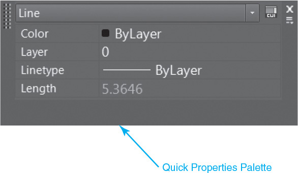
The initial properties displayed are dependent on the type of object you select. For example, text has a different list of properties than a line does. The properties of a circle are shown in Figure 6-26.
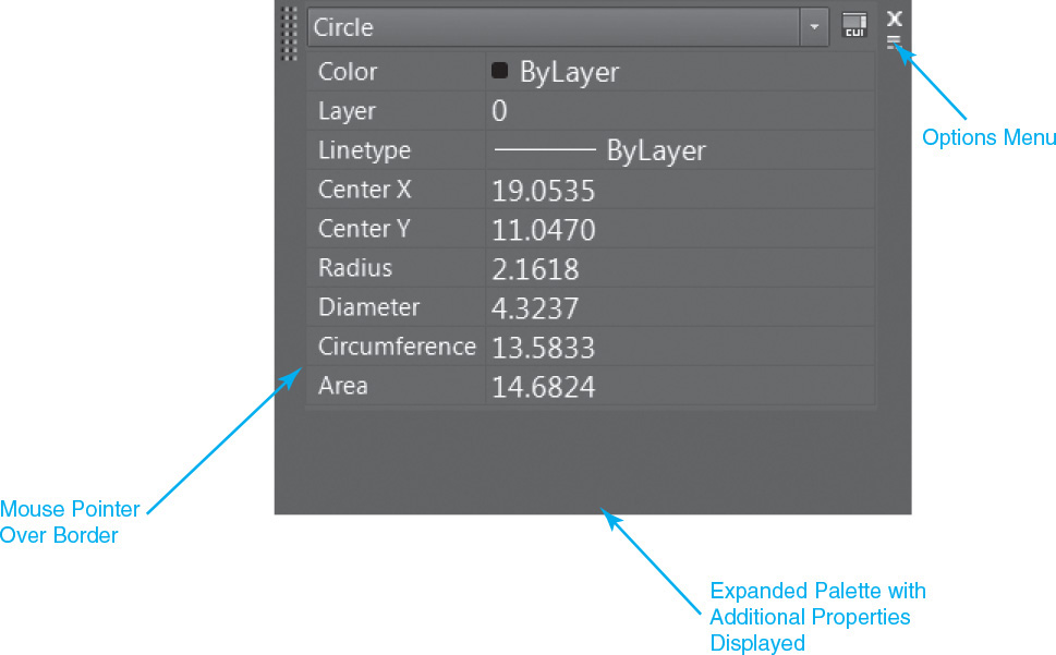
You can control the Quick Properties options and features on the Options menu that is displayed when you select the Options button on the title bar shown in Figure 6-26. The Location Mode cascade menu on the Options menu allows you to switch the palette from always displaying at the current cursor location to being in a static mode that behaves like the other typical AutoCAD palettes so that it stays where you place it in whatever display mode you set (docked, Auto-hide, etc.). Selecting the Settings... menu item from the Options menu displays the Quick Properties tab of the Drafting Settings dialog box shown in Figure 6-27.
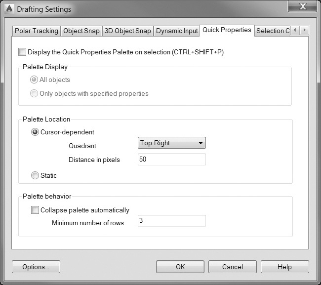
Using the Quick Properties tab you can control some of the same options mentioned previously plus certain more advanced features.
In the Palette Display area, you can control what type of objects will display the Quick Properties palette. By default, when the Quick Properties feature is on, the palette is displayed for every object you select. It is possible, using AutoCAD’s advance Customize User Interface (CUI) tool, to select which objects will cause the Quick Properties palette to be displayed. Additionally, you can even tell AutoCAD which properties to display. Both of these advanced topics are beyond the scope of this text.
The Palette Location area allows you to control whether the Quick Properties palette is static or is displayed at the current cursor location. Additionally, you control where the palette is located relative to the current cursor location by specifying one of four quadrants and the distance away from the cursor in pixels.
The Palette behavior area allows you to turn on and off the Auto-collapse feature, as well as select the initial number of property rows to display. The default is 3 rows.
Copying Properties Between Objects
AutoCAD gives you a way to copy the properties from one object to another. This is done through the MATCHPROP or PAINTER command.
Match Properties |
|
Ribbon & Panel: |
Home | Properties
|
Menu: |
Modify | Match Properties |
Command Line: |
MATCHPROP Or PAINTER |
Command Alias: |
None |

Note
The MATCHPROP and PAINTER commands are identical. AutoCAD simply has two names for the same command.
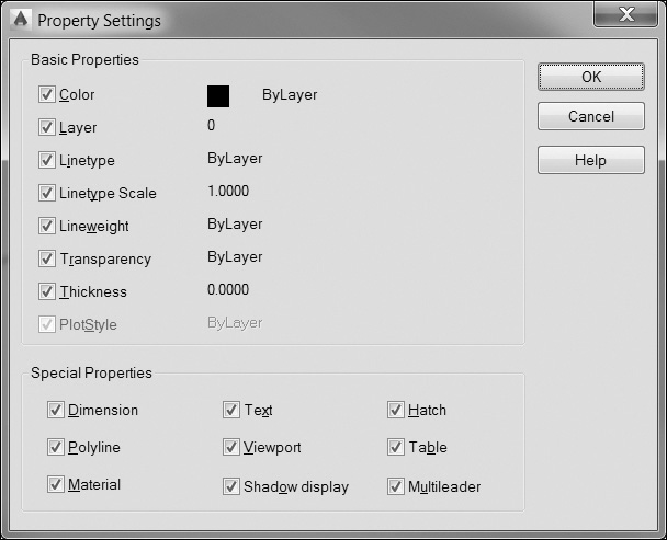
The MATCHPROP command prompts you to select a source object and a destination object. The properties from the source object are then applied to the destination object. There is a Settings option that allows you to control which object properties are applied to the destination object. When you choose the Settings option, AutoCAD shows you the Property Settings dialog box (see Figure 6-28). This shows you the properties of the source object and allows you to specify which property settings to apply to the destination object.
Creating Objects with Properties Based on Existing Objects
The Add Selected tool allows you to quickly create a new object in your drawing based on the general properties of an existing object. The properties that are included are color, layer, linetype, linetype scale, plot style, lineweight, and transparency. The tricky thing is that the only way to access the Add Selected tool is to first select the existing object that you want to base on and then right-click to display a shortcut menu with the tool now included, as shown in Figure 6-29.
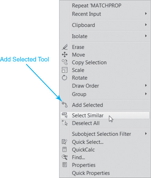
After selecting the Add Selected tool, AutoCAD starts the command that was used to create the existing object and updates the general properties to match the selected object.
In the following exercise, you’ll examine some of the different ways of changing object properties.
Exercise 6-9 Changing Object Properties
![]() Continue from Exercise 6-8.
Continue from Exercise 6-8.
![]() Set the Object layer current.
Set the Object layer current.
![]() Select the circle in your drawing. Notice that values in the Layer, Color, Linetype, and Lineweight drop-down lists all change to show you the property settings for the selected circle.
Select the circle in your drawing. Notice that values in the Layer, Color, Linetype, and Lineweight drop-down lists all change to show you the property settings for the selected circle.
![]() Open the Properties palette.
Open the Properties palette.
![]() Change the Linetype scale value to 2. The linetype scale of the circle will double. Press <Esc> to clear the circle selection and close the Properties palette.
Change the Linetype scale value to 2. The linetype scale of the circle will double. Press <Esc> to clear the circle selection and close the Properties palette.
![]() Select the line on layer Hidden. Again, the Properties drop-down lists show the values of the selected object.
Select the line on layer Hidden. Again, the Properties drop-down lists show the values of the selected object.
![]() Select the Object layer in the Layer Control drop-down list. The line is changed to the Object layer. Since the linetype, color, and lineweight properties of the line were all set to ByLayer, those properties were updated as well. Press <Esc> to clear line selection.
Select the Object layer in the Layer Control drop-down list. The line is changed to the Object layer. Since the linetype, color, and lineweight properties of the line were all set to ByLayer, those properties were updated as well. Press <Esc> to clear line selection.
![]() Double-click on the circle in the drawing. The Quick Properties palette is displayed.
Double-click on the circle in the drawing. The Quick Properties palette is displayed.
![]() Change the diameter to 3.0.
Change the diameter to 3.0.
![]() Press <Esc> to clear the circle selection and close the Quick Properties palette.
Press <Esc> to clear the circle selection and close the Quick Properties palette.
![]() Start the MATCHPROP command. AutoCAD prompts you to Select source object:. Select one of the lines on the Object layer.
Start the MATCHPROP command. AutoCAD prompts you to Select source object:. Select one of the lines on the Object layer.
![]() AutoCAD prompts you to Select destination objects(s) or
AutoCAD prompts you to Select destination objects(s) or ![]() . Select the zigzag line. All the properties of the zigzag line are changed to match the properties of the Object line. Press <Enter> or <Esc> to end the MATCHPROP command.
. Select the zigzag line. All the properties of the zigzag line are changed to match the properties of the Object line. Press <Enter> or <Esc> to end the MATCHPROP command.
![]() Save your drawing.
Save your drawing.
Using DesignCenter to Import Layers
In many cases, drawing information such as layers, linetypes, symbols, text styles, and dimension settings are common across multiple drawings. The layers you use in one drawing might be part of a company or project standard that is used over and over. AutoCAD’s DesignCenter is a tool that allows you to share common information and settings between multiple drawings.
Designcenter |
|
Ribbon & Panel: |
View | Palettes
|
Menu: |
Tools | Palettes | Design Center |
Command Line: |
ADCENTER |
Command Alias: |
DC |

The DesignCenter palette (see Figure 6-30) is arranged in tabs that show drawings you currently have open, drawings in other local or network folders, and drawings you’ve recently accessed.
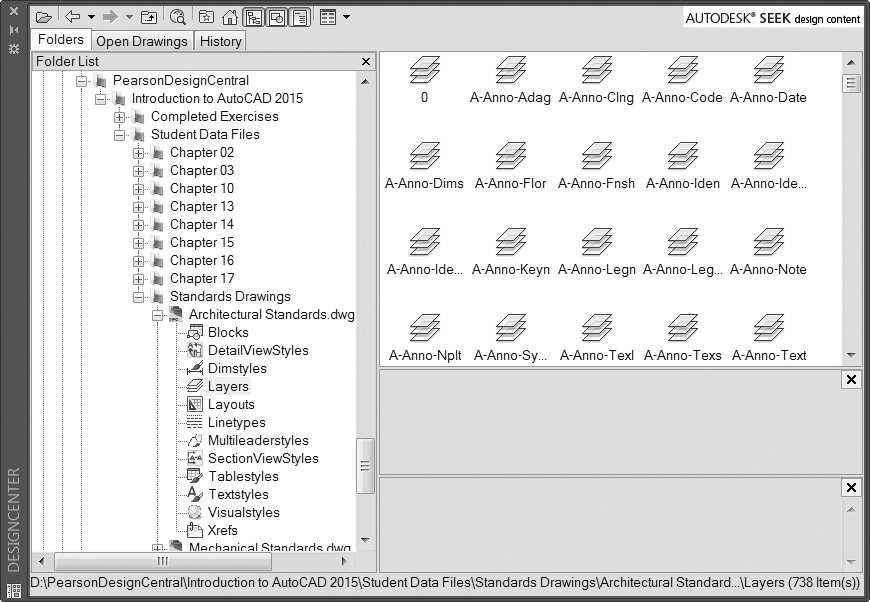
The Folders tab shows you a directory tree similar to what you might see in Windows Explorer. With the Folders tab, you can navigate to drawing files in any accessible local or network folder. The Open Drawings and History tabs show you a list of currently or recently opened drawing files.
When you select a drawing file in DesignCenter, AutoCAD shows you a list of drawing information contained in that drawing. The drawing information is divided into categories (Blocks, DetailViewStyles, Dimstyles, Layers, Layouts, Linetypes, Multileaderstyles, SectionViewStyles, Tablestyles, Textstyles, Visualstyles, and Xrefs), and within each category are the specific objects and settings contained within that drawing. These objects and settings can be copied into your current drawing by selecting them from the list on the right and then dragging them into the drawing area of your current drawing. The settings and objects are then copied into your drawing.
Note
When drawing objects such as blocks and xrefs are placed in the drawing, the objects are placed on the current layer. For settings such as layer definitions, dimension styles, and other nongraphical information, only the settings are loaded into the drawing. If an object or setting with the same name already exists in your drawing, DesignCenter will simply ignore duplicate items and not import them.
Exercise 6-10 Using DesignCenter to Import Layers
![]() Continue from Exercise 6-9.
Continue from Exercise 6-9.
![]() Choose the DesignCenter button from the Palettes panel on the View tab of the ribbon. This opens the DesignCenter palette. Position the palette on your screen anywhere you like.
Choose the DesignCenter button from the Palettes panel on the View tab of the ribbon. This opens the DesignCenter palette. Position the palette on your screen anywhere you like.
![]() In the Folders tab, navigate to the Standards Drawings folder in the student data files, and select the + box next to the Architectural Standards.dwg file. This will show the objects and settings available in this drawing.
In the Folders tab, navigate to the Standards Drawings folder in the student data files, and select the + box next to the Architectural Standards.dwg file. This will show the objects and settings available in this drawing.
To access student data files, go to www.pearsondesigncentral.com.
![]() Select the Layers item in the list. A list of available layers will appear in the right-hand pane.
Select the Layers item in the list. A list of available layers will appear in the right-hand pane.
![]() Select the A-ANNO-ADAG layer, hold down the <Shift> key, and select the A-ANNO-FNSH layer. AutoCAD will select all the layers between these two layers.
Select the A-ANNO-ADAG layer, hold down the <Shift> key, and select the A-ANNO-FNSH layer. AutoCAD will select all the layers between these two layers.
![]() Press and hold your mouse button on one of the selected layers and drag the layers into your drawing area. When you release the mouse button, the layers will be copied into your new drawing. In the command line, AutoCAD will respond with
Press and hold your mouse button on one of the selected layers and drag the layers into your drawing area. When you release the mouse button, the layers will be copied into your new drawing. In the command line, AutoCAD will respond with
Layer(s) added. Duplicate definitions will be ignored.
![]() Start the LAYER command to verify that the layers have been imported into your drawing.
Start the LAYER command to verify that the layers have been imported into your drawing.
![]() Close or hide the DesignCenter palette.
Close or hide the DesignCenter palette.
![]() Save the drawing.
Save the drawing.
Using Content Explorer to Import Layers
The AutoCAD Content Explorer is considered the next generation of DesignCenter. The Content Explorer palette (see Figure 6-31) is toggled on and off via the Explore button on the Add-ins tab of the ribbon.
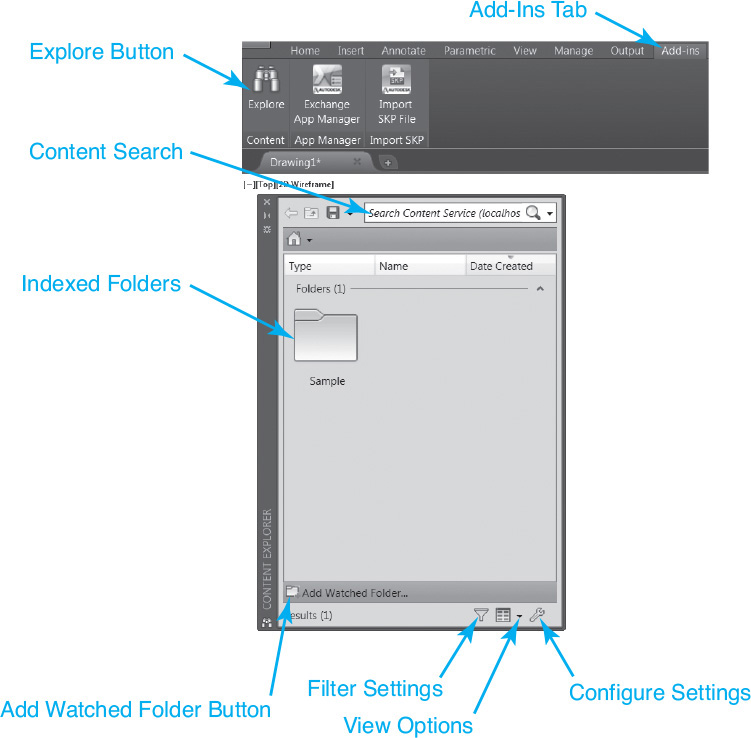
Content Explorer provides access to drawing information such as layers, linetypes, text styles, dimension settings, etc. in any drawing. However, unlike DesignCenter, Content Explorer is built upon an index that allows you to quickly search for drawing information across multiple folders with possibly thousands of files and have the results returned instantaneously.
In addition, by using Content Explorer you can find specific text strings or blocks in a drawing, then automatically open the file they are contained in, and zoom up on the found objects. Try that with DesignCenter!
Exercise 6-11 Using Content Explorer to Import Layers
![]() Continue from Exercise 6-10.
Continue from Exercise 6-10.
![]() Choose the Explore button from the Content panel on the Add-ins tab of the ribbon. This opens the Content Explorer palette. Position the palette on your screen anywhere you like.
Choose the Explore button from the Content panel on the Add-ins tab of the ribbon. This opens the Content Explorer palette. Position the palette on your screen anywhere you like.
![]() Select the Add Watched Folder... button near the bottom of the palette to display the Select Watched Folder window.
Select the Add Watched Folder... button near the bottom of the palette to display the Select Watched Folder window.
![]() Navigate to the Standards Drawings folder in the student data files, and select the OK button. AutoCAD will start building an index for all drawings in that folder.
Navigate to the Standards Drawings folder in the student data files, and select the OK button. AutoCAD will start building an index for all drawings in that folder.
To access student data files, go to www.pearsondesigncentral.com.
![]() Once the index is created, double-click on the Standards Drawings folder, and then double-click on the Architectural Standards.dwg file. This will show the objects and settings available in this drawing.
Once the index is created, double-click on the Standards Drawings folder, and then double-click on the Architectural Standards.dwg file. This will show the objects and settings available in this drawing.
![]() Select the I-LITE layer, drag it into the drawing window, and release the mouse button to copy the layer and all of its properties to the current drawing.
Select the I-LITE layer, drag it into the drawing window, and release the mouse button to copy the layer and all of its properties to the current drawing.
![]() Close or hide the Content Explorer palette.
Close or hide the Content Explorer palette.
![]() Save the drawing.
Save the drawing.
Layer Filters
When working in drawings that have a large number of layers, managing layer settings in a long list of layers can prove difficult. To help manage this, AutoCAD allows you to filter the list of layers. This allows you to display only the layers you are interested in or will be using. The Layer Filter list of the Layer Properties Manager palette allows you to create and manage these filters (see Figure 6-32).
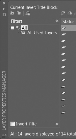
The filter tree shows you a hierarchy of layers, starting with all layers. Clicking on the All level will list all the layers in the drawing in the layer list area. Below the All filter is the All Used Layers filter. Selecting this will filter the layer list to show only the layers that are currently in use in the drawing. The All and All Used Layers filters are predefined filters that cannot be renamed or deleted. You can create your own custom layer filters.
The Filter Tree
To activate a layer filter, simply select it from the filter tree. The filter tree is hierarchical, which means that the filter is applied to the layers on the level above it in the tree.
Below the filter tree are two boxes: Invert filter and Indicate layers in use. Putting a check in the Invert filter box will reverse the effects of the filter. For example, if you choose the All Used Layers filter, putting a check in the Invert filter box will show you all the unused layers.
Checking the Indicate layers in use option will indicate which layers have drawing information on them by making the icon in the Status column darker for referenced layers and lighter for layers that do not have anything on them. This is a good way to determine which layers can be deleted and which layers cannot.
Property Filters
Property filters will filter your layer list based upon certain matching criteria. For example, you might create a filter that shows you only layers that start with characters “C-,” or a filter that shows only thawed layers, or only locked layers. You can also combine criteria. For example, you can create a filter that shows all layers that are both frozen and locked and contain the letter X in their name.
To create a property filter, choose the New Property Filter button. The Layer Filter Properties dialog box will appear (see Figure 6-33).
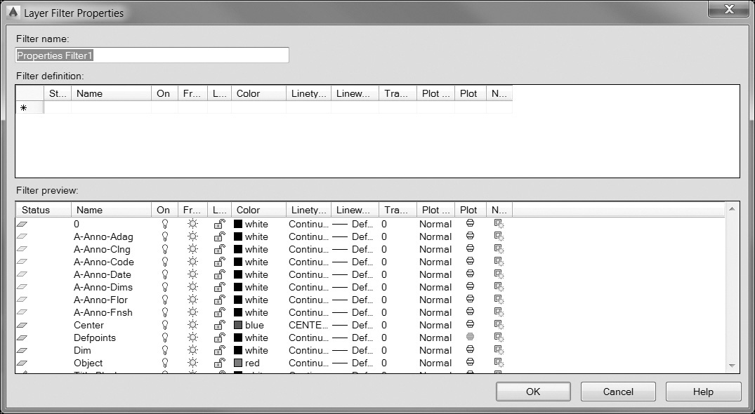
The Filter name: area allows you to change the name of your filter. You create a filter by selecting criteria in the Filter definition: area. You can select multiple criteria on a single row. As you specify filter criteria, the Filter preview: area shows you all the layers that match your filter. The various filter criteria are defined in the following table:
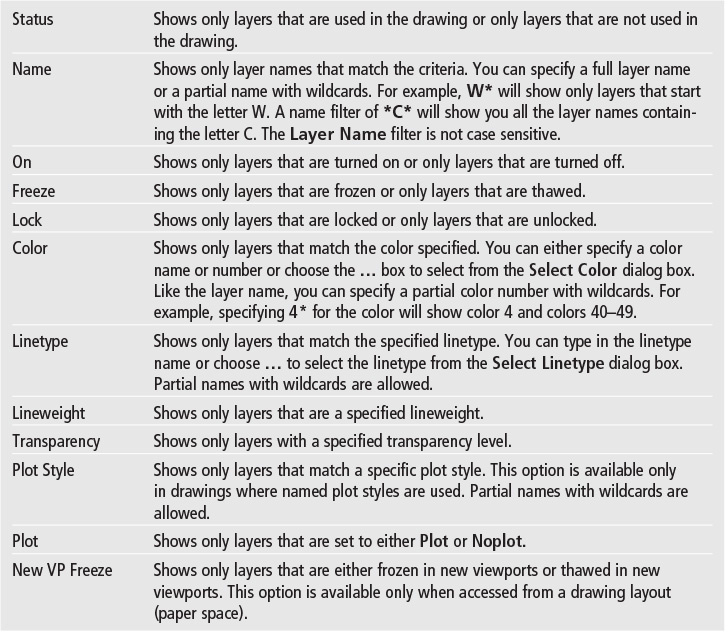
All the criteria you specify in a row are applied to the layer list. For example, a filter row with the name criteria of “A-” and “Frozen” will show only layers that both start with “A-” and are frozen.
Once you specify some criteria, a new row is added to the Filter definition: list. Each row is applied separately to the filter. For example, if you have one row that has a name criterion of “E-” and another row that has a name criterion of “Wall,” all layers that start with “E-” will be shown and all the layers that contain the word “WALL” will also be shown.
Note
Criteria within a single row are the equivalent of an AND search query. AutoCAD will show all the layers that meet all the criteria in that row (the first criterion AND the second criterion, etc.).
Criteria listed on separate rows are the equivalent of an OR search query. AutoCAD will show all the layers that match the criteria of any row (the first row OR the second row, etc.).
Exercise 6-12 Creating a Layer Property Filter
![]() Continue from Exercise 6-11.
Continue from Exercise 6-11.
![]() Start the LAYER command, and choose the New Property Filter button. The Layer Filter Properties dialog box will appear (see Figure 6-34).
Start the LAYER command, and choose the New Property Filter button. The Layer Filter Properties dialog box will appear (see Figure 6-34).
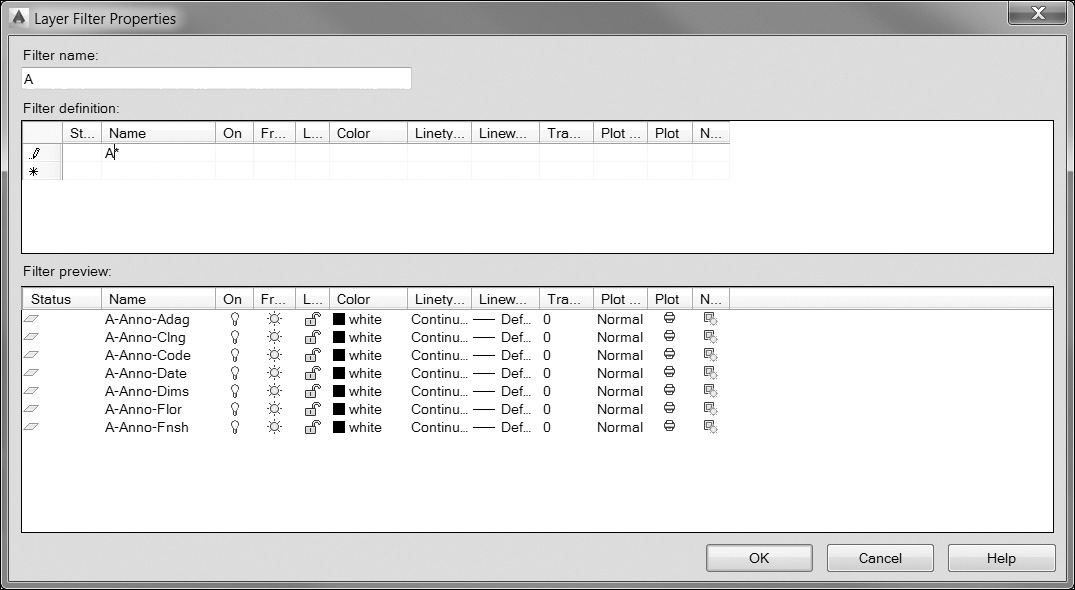
![]() Change the Filter name to A and click inside the Name criteria column. An asterisk (*) will appear in the Name column, and all the layers will appear in the Filter preview: area.
Change the Filter name to A and click inside the Name criteria column. An asterisk (*) will appear in the Name column, and all the layers will appear in the Filter preview: area.
![]() Type A-* in the Name column. The Filter preview: area will update to show you only layer names that start with A-.
Type A-* in the Name column. The Filter preview: area will update to show you only layer names that start with A-.
![]() Choose OK to save the filter and close the dialog box. The A filter will now appear in the Layer Filter area. The filter is applied to the layer list so only the A- layers are shown.
Choose OK to save the filter and close the dialog box. The A filter will now appear in the Layer Filter area. The filter is applied to the layer list so only the A- layers are shown.
![]() Select the Invert filter box. The filter is reversed, and all layers except the A- layers are shown.
Select the Invert filter box. The filter is reversed, and all layers except the A- layers are shown.
![]() Remove the check from the Invert filter box. Choose OK to end the LAYER command.
Remove the check from the Invert filter box. Choose OK to end the LAYER command.
![]() Select the Layer Control drop-down list. Notice that only layers that match the A filter are shown.
Select the Layer Control drop-down list. Notice that only layers that match the A filter are shown.
![]() Save the drawing.
Save the drawing.
Group Filters
A group filter allows you to filter your layer list to show only layers you select. The layers do not need to match any particular criteria; you simply select the layers you want to include in your filter. To create a group filter, choose the New Group Filter button in the Layer Properties Manager palette. AutoCAD will create a new group filter called Group Filter1 and highlight the name. You can then type a new name for the filter. To add layers to the filter, select the layers from the layer list on the right side and drag them onto the group filter name on the left side.
Exercise 6-13 Creating a Group Filter
![]() Continue from Exercise 6-12.
Continue from Exercise 6-12.
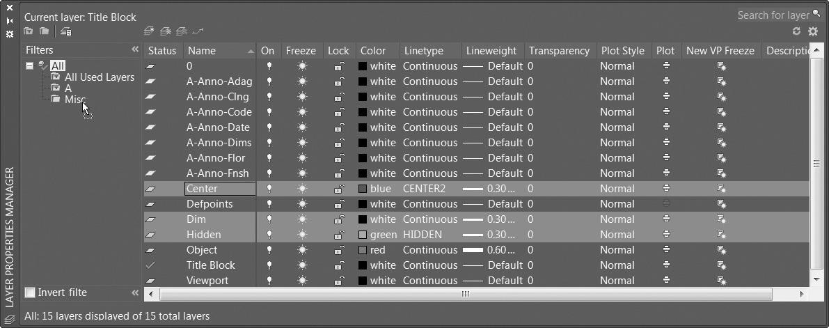
![]() Start the LAYER command, and choose the New Group Filter button. AutoCAD creates a new group filter called Group Filter1 and highlights the name. Type Misc for the group filter name. The layer list is now empty because the new group filter is active and has no layers in it.
Start the LAYER command, and choose the New Group Filter button. AutoCAD creates a new group filter called Group Filter1 and highlights the name. Type Misc for the group filter name. The layer list is now empty because the new group filter is active and has no layers in it.
![]() Select All in the Layer Filter area to show all the layers. Hold down the <Ctrl> key, and select the Center, Dim, and Hidden layers from the layer list. Click and drag the layers onto the Misc filter and release the mouse button (see Figure 6-35). The selected layers are added to the group filter.
Select All in the Layer Filter area to show all the layers. Hold down the <Ctrl> key, and select the Center, Dim, and Hidden layers from the layer list. Click and drag the layers onto the Misc filter and release the mouse button (see Figure 6-35). The selected layers are added to the group filter.
![]() Select the All filter and choose OK to end the LAYER command.
Select the All filter and choose OK to end the LAYER command.
![]() Save the drawing.
Save the drawing.
Search Filter
In the top right corner of the Layer Properties Manager palette is a box that says Search for layer. This is a layer search filter that allows you to do a temporary name filter on the current list of layers. You can type in a layer name (including wildcards) to show a list of layers that match that name. The search filter cannot be saved; it works only while the dialog box is open or until you select another filter. The search filter applies only to the list of layers shown in the layer list at the time the search is done.
Layer States Manager
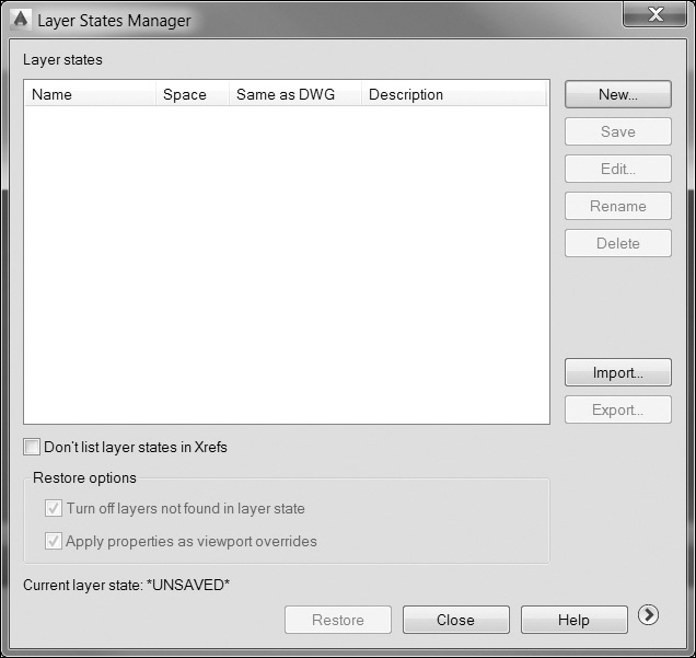
There may be times when you have a set of layer settings that you use or need to restore at certain times. For example, you might want to freeze a set of layers before you plot, or you might want to lock certain layers before you share them with others. The Layer States Manager will save a snapshot of layer settings that you can then recall at any time. To create a layer state, set the layers to the setting you want to save, and then start the LAYERSTATE command to display the Layer States Manager dialog box (see Figure 6-36) by selecting the Layer States Manager button in the Layer Properties Manager palette.
Layer States Manager |
|
Layer Properties Manager: |
|
Menu: |
Format | Layer States Manager |
Command Line: |
LAYERSTATE |
Command Alias: |
LAS |

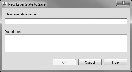
Choose the New... button to create a new layer state. The New Layer State to Save dialog box appears (see Figure 6-37), and you are asked for a layer state name. You can also provide an optional description for the layer state. Once you’ve supplied a name, choose OK, and you’ll be returned to the Layer States Manager dialog box.
It is possible to edit a layer state directly by selecting the Edit... button so that the layer state does not need to be deleted and re-created. Selecting the Edit... button displays the Edit Layer State dialog box so that you can update any of the standard layer properties, add new layers, or delete existing layers from the currently selected layer state.
Selecting the More Restore Options arrow button at the bottom right of the dialog box displays the Layer properties to restore options on the right of the dialog box so you can control which layer properties you wish to save and restore. Simply select which properties you wish to maintain.
Layer states can be exported to a file. This allows you to create standard layer settings that can be shared among multiple drawings in a project or used within a company standard. Use the Export... and Import... buttons in the Layer States Manager dialog box to export a layer state setting or to import an existing layer state file with an LAS extension. It is also possible to import layer states directly from DWG, DWT, or DWS files.
To restore a layer state, choose the Layer States Manager button on the Layer Properties Manager palette, select the layer state you wish to restore, and then choose the Restore button. All the settings for that layer state will be restored.
Exercise 6-14 Creating and Restoring Layer States
![]() Continue from Exercise 6-13.
Continue from Exercise 6-13.
![]() Start the LAYER command and select the All filter from the filter tree.
Start the LAYER command and select the All filter from the filter tree.
![]() Choose the Layer States Manager button to display the Layer States Manager dialog box.
Choose the Layer States Manager button to display the Layer States Manager dialog box.
![]() Choose the New... button to display the New Layer State to Save dialog box. Type Default in the New layer state name: area and choose OK to close the dialog box. You are returned to the Layer States Manager dialog box.
Choose the New... button to display the New Layer State to Save dialog box. Type Default in the New layer state name: area and choose OK to close the dialog box. You are returned to the Layer States Manager dialog box.
![]() Select the More Restore Options arrow button at the bottom right of the dialog box to display more options. Choose the Select All button and put a check in the Turn off layers not found in layer state box. Choose Restore to save the layer state and close the dialog box. You are now returned to the Layer Properties Manager palette.
Select the More Restore Options arrow button at the bottom right of the dialog box to display more options. Choose the Select All button and put a check in the Turn off layers not found in layer state box. Choose Restore to save the layer state and close the dialog box. You are now returned to the Layer Properties Manager palette.
![]() Select the A filter to filter the layer list. Select all the layers in the list and select the snowflake icon in the Freeze column to freeze all the layers.
Select the A filter to filter the layer list. Select all the layers in the list and select the snowflake icon in the Freeze column to freeze all the layers.
![]() Select the Misc group filter to refilter the layer list. Select all the layers and set the color to white (color 7). Choose the All filter to see all layers. Notice the changes you made to the layer settings.
Select the Misc group filter to refilter the layer list. Select all the layers and set the color to white (color 7). Choose the All filter to see all layers. Notice the changes you made to the layer settings.
![]() Select the Layer States Manager button. The Default layer state is highlighted. Choose Restore to restore the layer settings. The layer settings should now be restored to their previous state.
Select the Layer States Manager button. The Default layer state is highlighted. Choose Restore to restore the layer settings. The layer settings should now be restored to their previous state.
![]() Save the drawing.
Save the drawing.
Object Visibility
It is possible to control object visibility independent of layer visibility via the Object Visibility tools located in the status tray on the far right of the status bar shown in Figure 6-38.
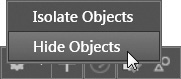
The Isolate Objects tool displays only the objects you select in the drawing. All other objects are hidden. The Hide Objects tool, on the other hand, hides all of the objects you select in the drawing. All other objects are visible.
You can use the Isolate Objects and Hide Objects tools together to display only the objects that are relevant to your current task. For example, you can first use the Isolate Objects tool to select an area of the drawing you want to edit using a window selection technique and then use the Hide Objects tool to hide individual objects within the displayed group. When you are done, you can quickly restore the original drawing display by selecting the End Object Isolation tool, which is displayed on the same Object Visibility menu when either tool is in use.
Note
• You can also use the ISOLATEOBJECTS and HIDEOBJECTS commands to control object visibility.
• The lightbulb icon in the status tray on the status bar appears dimmed when either the Isolate Objects or Hide Objects tool is in use.
Chapter Summary
A well-organized drawing is something every CAD user should strive for. Clear and concise CAD standards and drawing objects placed on their proper layers can make the difference between a drawing that is easy to read and understand and one that is confusing. Good layer management practices are critical in group settings where multiple people will be accessing and editing your drawings. Incorporating different standard linetypes and lineweights to delineate different types of information in a drawing helps to visually communicate design intent and display drawing information in a concise fashion.
One of the beauties of CAD, as an old boss used to tell me, is the ability to update and modify a drawing quickly. To tell the truth, I think he abused that capability considering the many times he made me revise the same drawings. But, it is a fact of life in the drafting world that drawings constantly change. Using the different property management tools introduced in this chapter provides the most efficient means of implementing those changes. It’s not called Quick Properties for nothing.
Rather than creating a bunch of layers and updating all of their corresponding properties in every drawing, it is possible to save significant amounts of time using the DesignCenter palette or Content Explorer to drag and drop multiple layer definitions from any existing drawing on your system into your current drawing. To help manage the huge amount of layers and their various properties that can end up in a drawing over its life span, AutoCAD provides a means to filter layer information so you can reduce the infoglut. On top of that, complex layer groups and their property settings can be saved to a layer state so that they may be restored later in the current drawing or even in other drawings on a whole project so that everyone is literally on the same page!
Chapter Test Questions
Multiple Choice
Circle the correct answer.
1. A layer is:
a. A separate drawing that you merge into your drawing
b. The only way to control the color of drawing objects
c. A collection of color, linetype, lineweight, and other display settings
d. A 3D setting
2. Turning a layer off:
a. Prevents objects on that layer from being seen
b. Prevents objects on that layer from being edited
c. Deletes all the objects on a layer
d. Is the same as freezing a layer
3. The color blue is AutoCAD Color Index number:
a. 3
b. 4
c. 5
d. 6
4. An RGB color number of 0,255,0 is what color?
a. Red
b. Green
c. Blue
d. Black
e. White
5. AutoCAD linetypes:
a. Consist of only lines and spaces
b. Are loaded automatically when you assign them to a layer
c. Cannot be modified
d. Must be loaded into the drawing before they can be used
6. Deleting a layer:
a. Deletes the layer and all the objects on the layer
b. Deletes all the objects on a layer but keeps the layer name in the drawing
c. Can be done only when a layer is unused
d. Can be done at any time regardless of whether the layer is used or not
7. The LTSCALE setting:
a. Is a global scale factor applied to all objects’ linetypes
b. Affects the lineweight of all objects
c. Affects the plot scale of layout viewports
d. Does not affect objects that have an individual object linetype scale
8. An object with a color of ByLayer:
a. Gets its color setting from its layer
b. Is white
c. Is white until a hard-coded color is assigned to it
d. Is always the same color regardless of its layer color setting
9. Property filters:
a. Are case sensitive
b. Can filter only layers based on a single criterion
c. Can use wildcards
d. Are not based on any specific criteria
10. Group filters:
a. Are case sensitive
b. Can filter only layers based on a single criterion
c. Can use wildcards
d. Are not based on any specific criteria
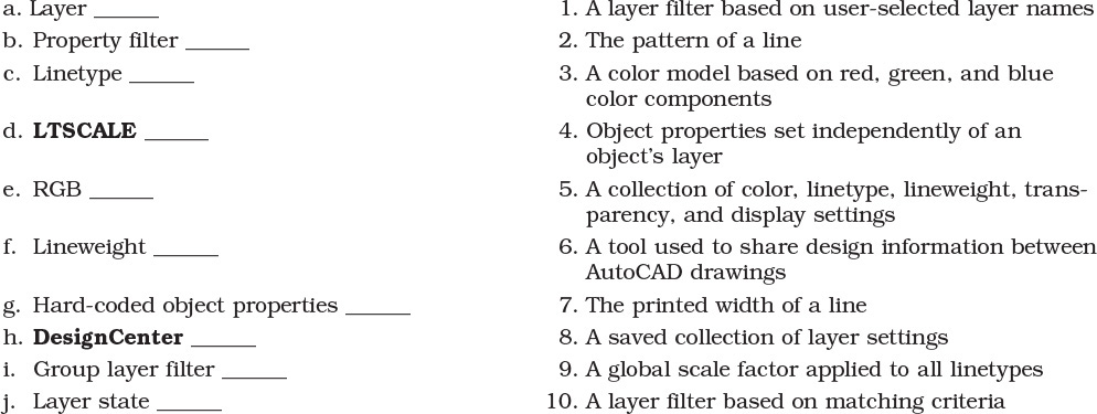
True or False
Circle the correct answer.
1. True or False: Layer 0 cannot be deleted.
2. True or False: Lineweight appears only when you plot a drawing.
3. True or False: Linetypes can be modified, and new linetypes can be created.
4. True or False: A layer can be deleted only if it is unused in the drawing.
5. True or False: The Layer Control drop-down list always shows all the layers in a drawing.
6. True or False: Layers can be imported from other drawing files.
7. True or False: The MATCHPROP and PAINTER commands do the same thing.
8. True or False: A search filter takes effect only while the LAYER command is active.
9. True or False: Layer states can be exported and shared between multiple drawings.
10. True or False: DesignCenter is used only to insert blocks from other drawings.
1. Start a new drawing using the acad.dwt template. Set the UNITS to Architectural with 1/16″ precision. Set the LTSCALE to 6.
2. Create the following layers:
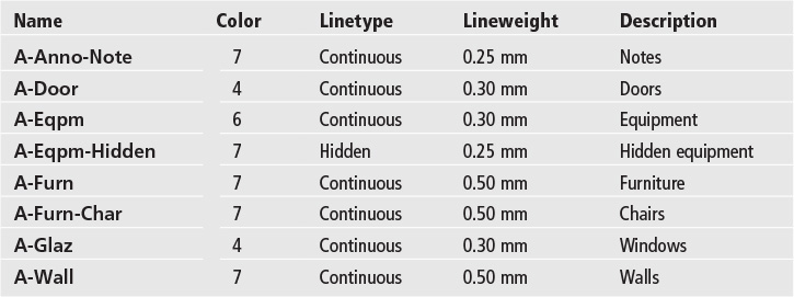
3. Draw the desk, monitor, computer tower, mouse, chair, and keyboard shown in Figure 6-39. Draw the desk on the A-Furn layer. Place the computer on the A-Eqpm-Hidden layer. Place all other objects on the A-Eqpm layer.
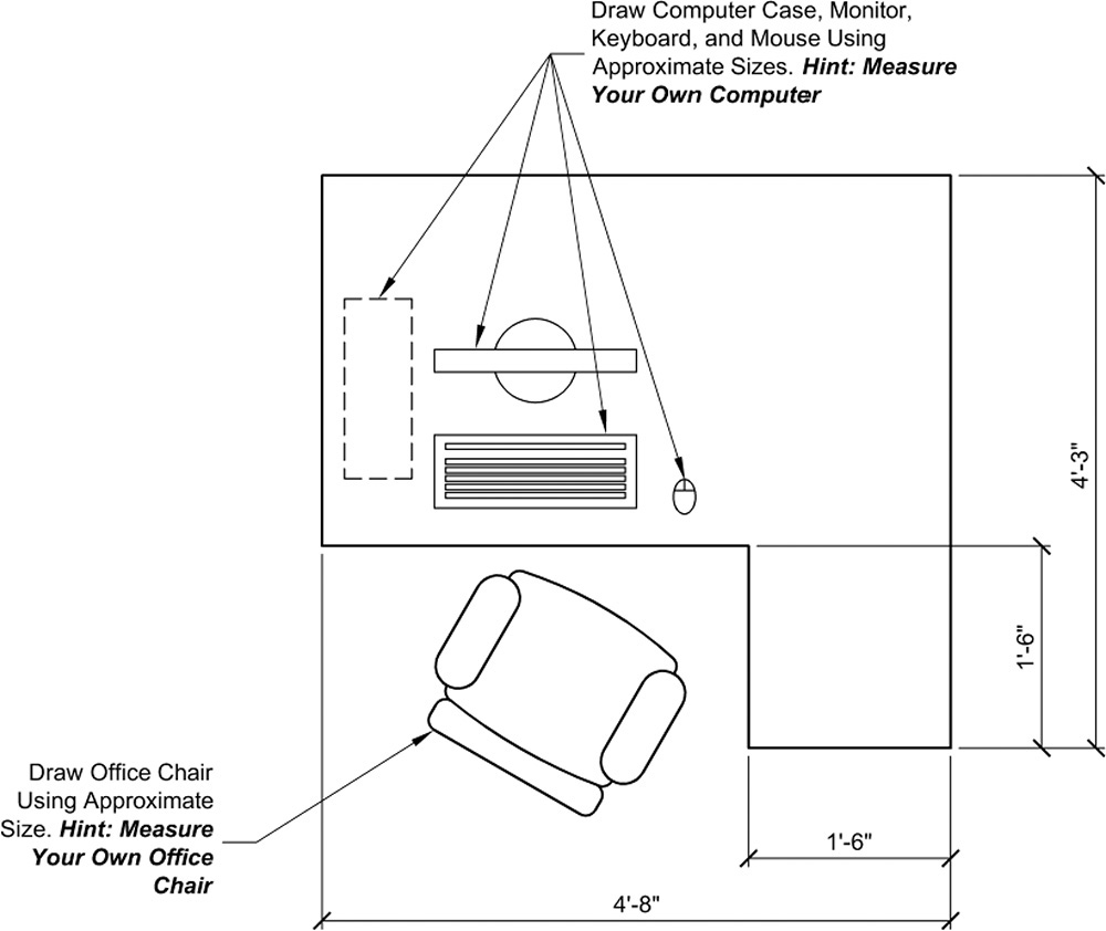
4. Do not draw dimensions or text.
5. Save the drawing as P6-1.
![]() Project 6-2: B-Size Mechanical Border, continued from Chapter 5 [INTERMEDIATE]
Project 6-2: B-Size Mechanical Border, continued from Chapter 5 [INTERMEDIATE]
1. Open the template file Mechanical B-Size.DWT from Project 5-2 in Chapter 5.
2. Create the following layers:
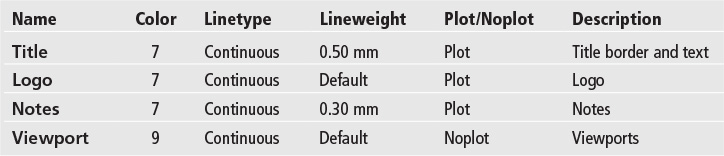
3. Place the existing geometry on layer Title.
4. Add the line work shown in Figure 6-40 to the drawing. Use the Title layer for all geometry. Do not draw dimensions.
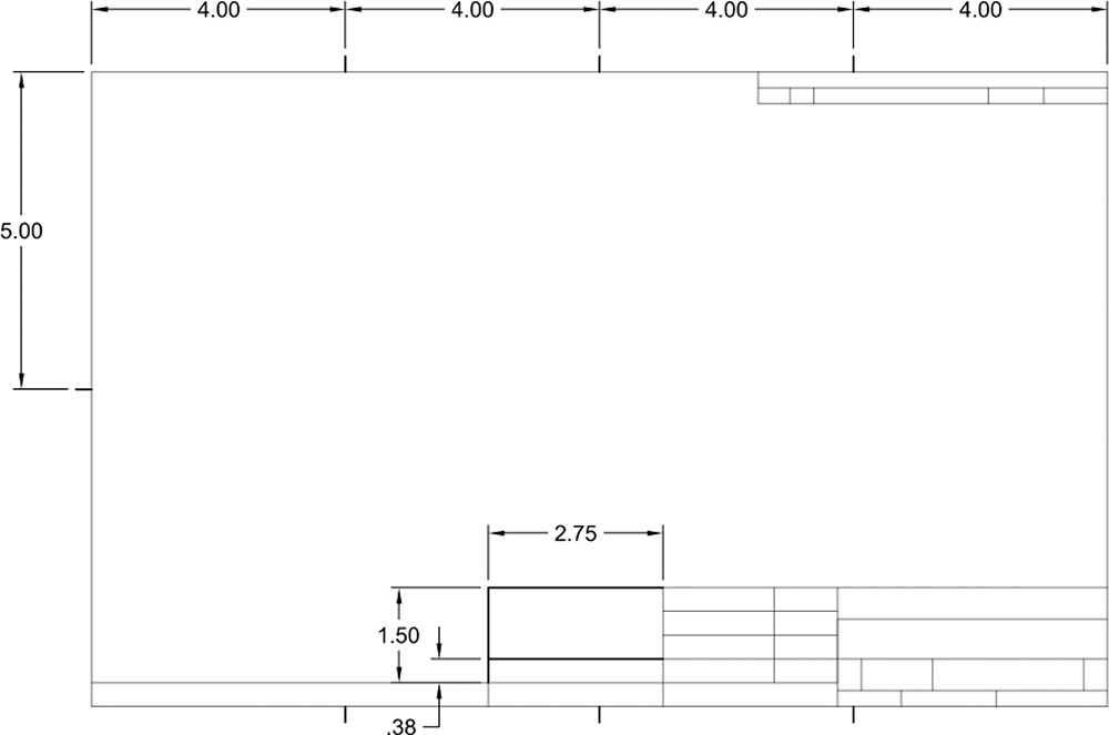
5. Save the drawing.
![]() Project 6-3: Architectural D-Size Border, continued from Chapter 5 [ADVANCED]
Project 6-3: Architectural D-Size Border, continued from Chapter 5 [ADVANCED]
1. Open the template file Architectural D-Size.DWT from Project 5-3 in Chapter 5.
2. Create the following layers:
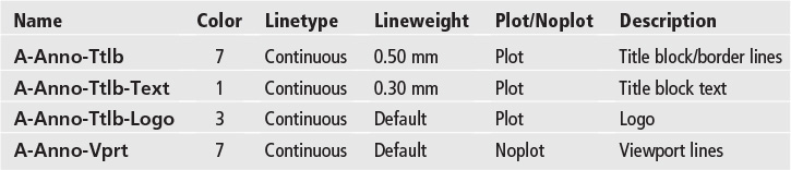
3. Put all the existing line work on layer A-Anno-Ttlb.
4. Save the drawing.
![]() Project 6-4: Electrical Schematic, continued from Chapter 5 [BASIC]
Project 6-4: Electrical Schematic, continued from Chapter 5 [BASIC]
1. Open drawing P5-4 from Chapter 5.
2. Create the following layers:
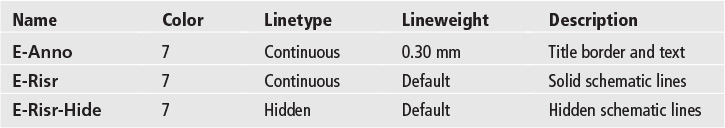
3. Change the solid geometry shown in Figure 6-41 to the E-Risr layer. Change the hidden geometry shown in Figure 6-41 to the E-Risr-Hide layer.
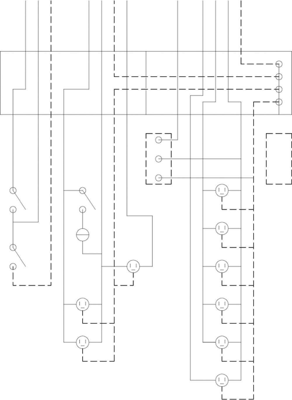
4. Save the drawing as P6-4.
![]() Project 6-5: Residential Architectural Plan, continued from Chapter 5 [ADVANCED]
Project 6-5: Residential Architectural Plan, continued from Chapter 5 [ADVANCED]
1. Open drawing P5-5 from Chapter 5.
2. Create the following layers:
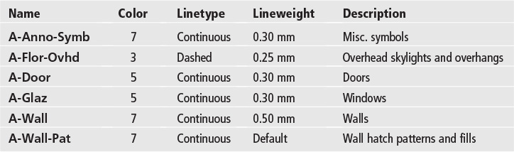
3. Set the LTSCALE to 24.
4. Place all existing walls on the A-Wall layer.
5. Draw the geometry shown in Figure 6-42 on the appropriate layer.
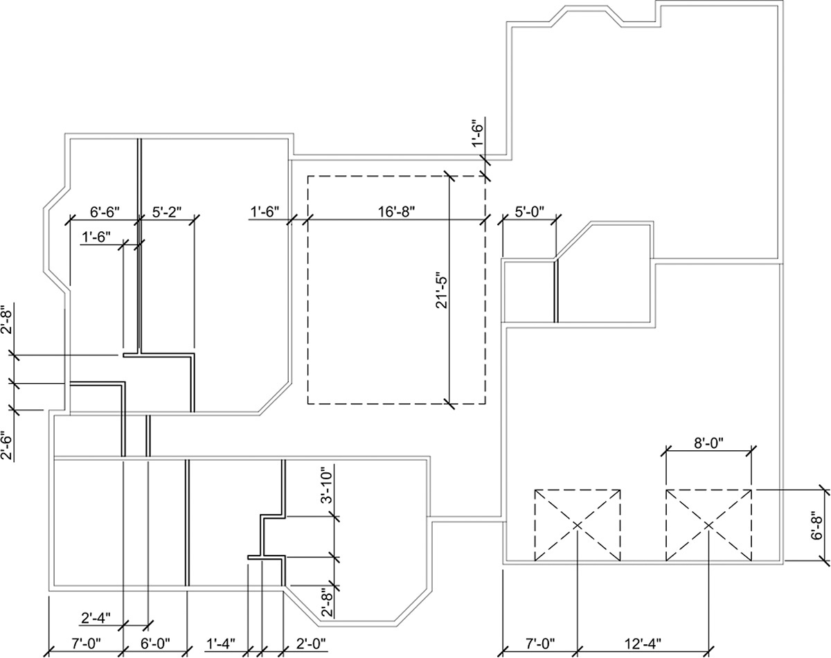
6. Save the drawing as P6-5.