
Chapter 9. Drawing and Editing Complex Objects
• Draw polylines with straight line segments
• Create rectangles using two points
• Make multisided polygons
• Create solid and hollow donuts
• Draw revision clouds
• Edit polylines as a unit
Introduction
AutoCAD provides a number of complex line objects that consist of multiple segments but are treated as a single line with multiple points:
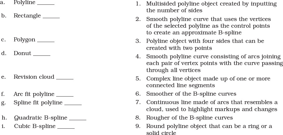
• Polyline
• Rectangle
• Polygon
• Donut
• Revision cloud
Complex line objects serve many different purposes and needs. Polylines allow you to define a closed boundary that can be used to calculate an enclosed area. Polylines are also used extensively to create contour lines on civil engineering maps.
contour line: A line on a map that joins points of equal elevation.
In fact, AutoCAD uses polylines to create the rectangles, polygons, donuts, and revision clouds described in this chapter. This chapter explores the commands used to create and edit these different complex line objects. Also covered is the ability to break complex line objects down into their individual line and arc segments using the EXPLODE command.
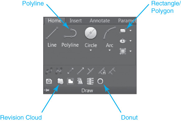
Most of the commands, with the exception of the EXPLODE command, are located on the Draw panel on the Home tab of the ribbon, as shown in Figure 9-1.
Drawing Polylines
A polyline is a complex line object made up of one or more connected line segments and/or arcs that are treated as a single line (see Figure 9-2).
Polyline |
|
Ribbon & Panel: |
Home | Draw
|
Menu: |
Draw | Polyline |
Command Line: |
PLINE |
Command Alias: |
PL |

Polylines are created using the PLINE command.
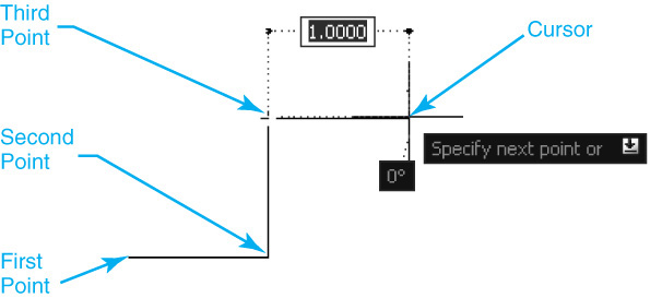
When you start the PLINE command, AutoCAD prompts you to Specify start point:. You can either type in a coordinate value or pick a point in your drawing, similar to using the LINE command. After you specify the first point, AutoCAD will continue to prompt you to Specify next point or ![]() until you press <Enter> without specifying a point, as shown in Figure 9-3.
until you press <Enter> without specifying a point, as shown in Figure 9-3.
Tip
You can specify points when drawing a polyline using absolute, relative, or polar coordinate entry methods. It is also possible to use direct distance entry with either the Ortho Mode or Polar Tracking drawing tool.
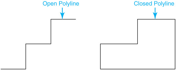
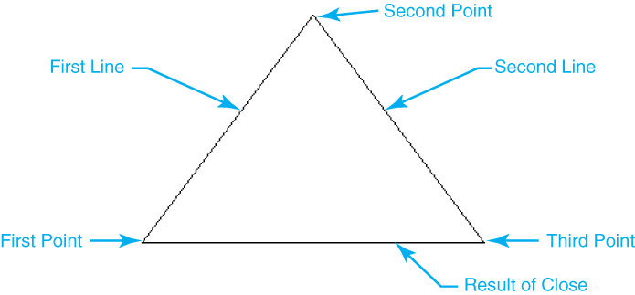
You can create a closed polyline line using the Close option just as with the LINE command, except that the closed polyline creates a true closed polygon, unlike the LINE command, which creates individual line segments. The Close option will draw a line segment from the last point back to the start point. Figure 9-4 shows the result of selecting the Close option after drawing two line segments.
Tip
It is possible to get the area and perimeter of a closed polyline using the LIST command. To use the LIST command type LIST or LI, select the polyline, and press <Enter>. AutoCAD switches to the full text window and lists the area, perimeter, vertex point information, and a few other properties. You can also retrieve the same information using the Properties palette or the MEASUREGEOM command using the Area option.
The PLINE command also has a built-in Undo option that allows you to undo points as you draw. Using the Undo option repeatedly will undo all the polyline points back to the first point.
Note
By default, AutoCAD creates what’s referred to as an optimized polyline that has the object name LWPOLYLINE. The LW stands for lightweight because the method in which polylines store vertex point information has been optimized. The old unoptimized polyline format still exists for legacy reasons and is referred to simply as a POLYLINE object.
Tip
You can control the type of polyline used via the PLINETYPE system variable. PLINETYPE controls both the creation of new polylines and the conversion of existing polylines in drawings from previous releases of AutoCAD. PLINETYPE has three settings.
0: Polylines in older drawings are not converted when opened; PLINE command creates old-format polylines.
1: Polylines in older drawings are not converted when opened; PLINE command creates optimized polylines.
2: Polylines in AutoCAD Release 14 or older drawings are converted when opened; PLINE creates optimized polylines.
The default setting is 2.
Exercise 9-1 Drawing a Polyline
![]() Start a new drawing using the acad.dwt drawing template.
Start a new drawing using the acad.dwt drawing template.
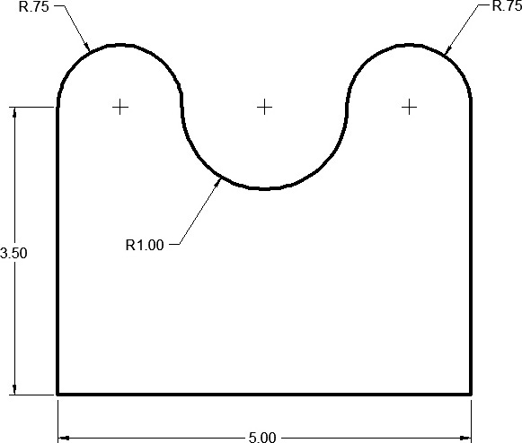
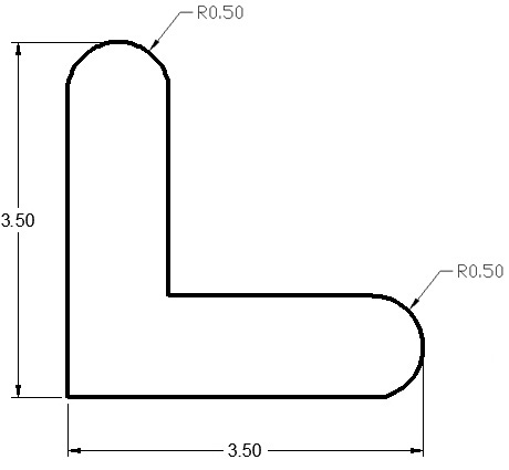
![]() Create the drawing shown in Figure 9-5 using the PLINE command. Do not draw dimensions.
Create the drawing shown in Figure 9-5 using the PLINE command. Do not draw dimensions.
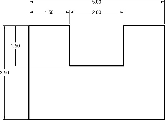
![]() The polyline should be closed using the Close option.
The polyline should be closed using the Close option.
![]() Save the drawing as CH9_EXERCISE1.
Save the drawing as CH9_EXERCISE1.
Drawing Polyline Arcs
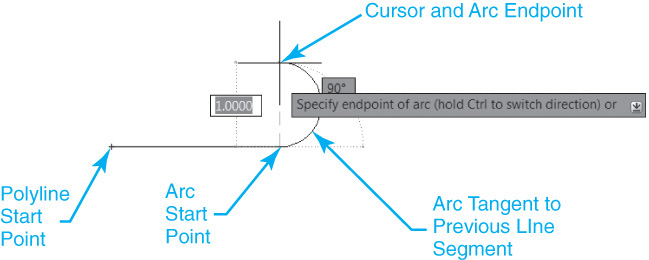
It is possible to switch from drawing line segments to drawing arcs when creating a polyline using the Arc option. By default, specifying an arc endpoint creates an arc that is tangent to the last line or arc segment, as shown in Figure 9-6.
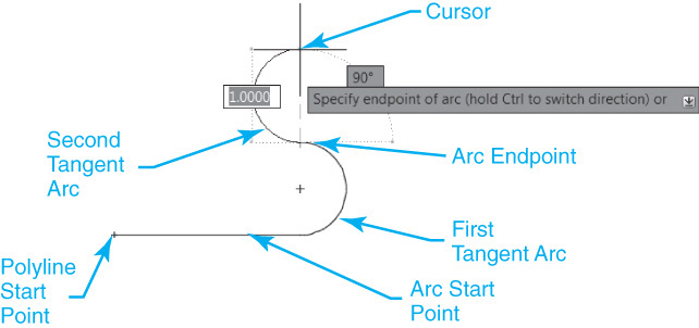
The direction of the arc is determined by where the arc endpoint is located relative to the current polyline point. If you continue to specify points in response to the Specify endpoint of arc (hold Ctrl to switch direction) or ![]() prompt, AutoCAD will create multiple tangent arc segments, as shown in Figure 9-7.
prompt, AutoCAD will create multiple tangent arc segments, as shown in Figure 9-7.

Tip
Pressing the <Ctrl> key while creating a polyline arc allows you to draw it in the opposite direction.
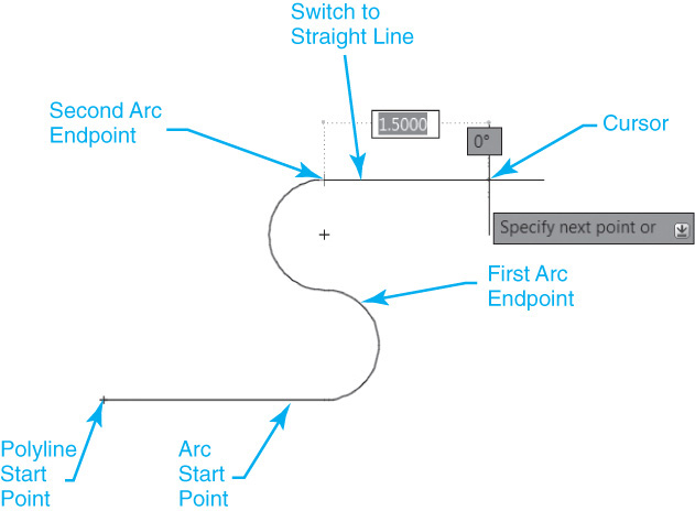
You can switch back to drawing straight line segments using the Line option, as shown in Figure 9-8.
There are a number of other options for creating polyline arcs, which are explained in the following sections.
Exercise 9-2 Drawing Tangent Polyline Arcs
![]() Continue from Exercise 9-1.
Continue from Exercise 9-1.
![]() Create the drawing shown in Figure 9-9 using the PLINE command and the default tangent Arc option.
Create the drawing shown in Figure 9-9 using the PLINE command and the default tangent Arc option.
![]() Save the drawing.
Save the drawing.
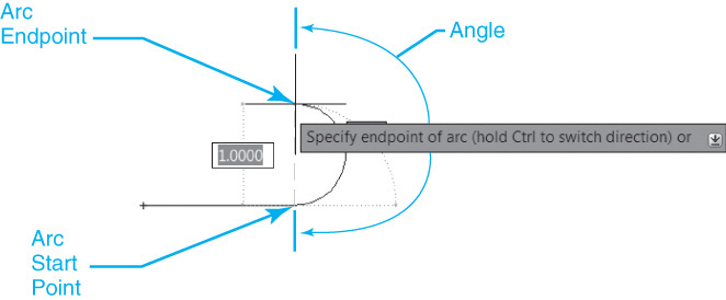
Angle Option
The Angle option allows you to specify the included angle of the arc segment from the start point.
After you enter the angle, you can specify an endpoint or enter one of the following options:
CEnter: Allows you to specify the center of the arc segment
Radius: Allows you to specify the radius of the arc segment. You can pick a point to indicate the direction or enter an angle at the keyboard
Figure 9-10 shows the results of drawing a polyline arc using the Angle option.
Note
Entering a positive number creates counterclockwise arc segments. Entering a negative number creates clockwise arc segments.
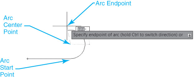
CEnter Option
The CEnter option allows you to specify the center of the arc segment. You can pick a point or enter a coordinate value at the keyboard.
After you enter the point, you can specify an endpoint or enter one of the following options:
Angle: Allows you to enter the included angle of the arc segment from the start point
Length: Allows you to specify the chord length of the arc segment
Figure 9-11 shows the results of drawing a polyline arc using the CEnter option.
Note
AutoCAD draws the new arc segment tangent to the previous arc segment if the previous segment is an arc.
Close Option
The Close option allows you to close a polyline with an arc segment.
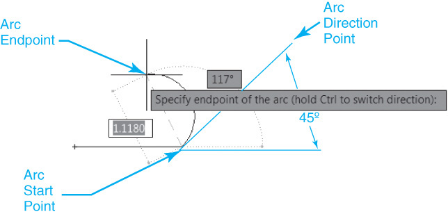
Direction Option
The Direction option allows you to indicate the starting direction for the arc segment. You can pick a point or enter a coordinate value at the keyboard.
After you enter the angle, you can pick a point or enter a coordinate value at the keyboard.
Figure 9-12 shows the results of drawing a polyline arc using the Direction option.
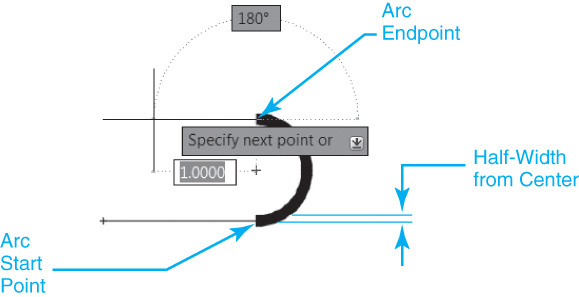
Halfwidth Option
The Halfwidth option allows you to specify the width from the center of a wide polyline segment to one of its edges. After you select the Halfwidth option, AutoCAD prompts you to Specify starting half-width<current>:. Enter a value or press <Enter> to use the current halfwidth. AutoCAD then prompts you to Specify ending half-width <starting width>:. You can either enter a different half-width value to create a tapered arc or press <Enter> for a uniform width.
Figure 9-13 shows the results of drawing a polyline arc using the Halfwidth option.
Note
The ending half-width becomes the uniform half-width for all new segments until you change the half-width again.
Line Option
The Line option exits the Arc option and returns to the initial PLINE command prompt so you can draw straight line segments.
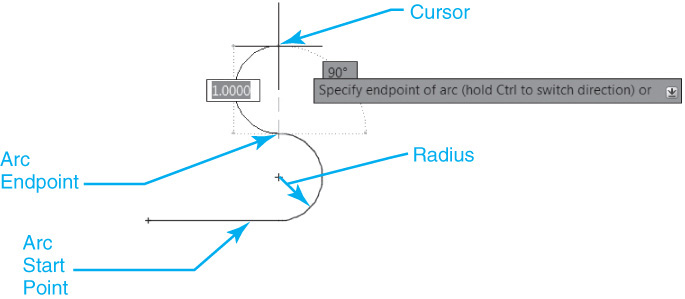
Radius Option
The Radius option allows you to specify the radius of the arc segment.
After you enter the radius, you can specify an endpoint or select the Angle option. The Angle option allows you to enter the included angle of the arc segment from the start point. After you enter the angle, you can pick a point to indicate the direction or enter an angle at the keyboard.
Figure 9-14 shows the results of drawing a polyline arc using the Radius option.
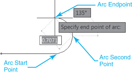
Second Pt Option
The Second Pt option allows you to specify the second point and the endpoint of a three-point arc. You can pick a point or enter a coordinate value at the keyboard.
After you specify the second point, you can pick a point or enter a coordinate value at the keyboard.
Figure 9-15 shows the results of drawing a polyline arc using the Second Pt option.
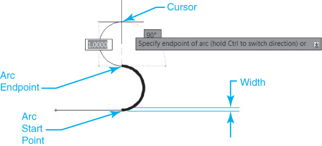
Width Option
The Width option allows you to change the width of the next arc segment. After you select the Width option, AutoCAD prompts you to Specify starting width<current>:. Enter a value or press <Enter> to use the current width. AutoCAD then prompts you to Specify ending width<starting width>:. You can either enter a different width value to create a tapered arc or press <Enter> for a uniform width.
Figure 9-16 shows the results of drawing a polyline arc using the Width option.
Note
The ending width becomes the uniform width for all new segments until you change the width again.
Exercise 9-3 Drawing Complex Polyline Arcs
![]() Continue from Exercise 9-2.
Continue from Exercise 9-2.
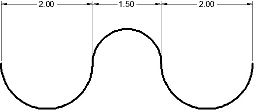
![]() Create the drawing shown in Figure 9-17 using the PLINE command and the Arc options covered in this section. Do not draw dimensions.
Create the drawing shown in Figure 9-17 using the PLINE command and the Arc options covered in this section. Do not draw dimensions.
![]() Close the polyline using the PLINE command’s Close option.
Close the polyline using the PLINE command’s Close option.
![]() Save the drawing.
Save the drawing.
Drawing Polylines with a Width
It is possible to assign a physical width to a polyline using the Width option. In fact, it is possible to vary a polyline’s width between vertex points using the Width option so that a polyline segment can be tapered.
Note
Polyline width is not related to the lineweight property discussed in Chapter 6. Polyline width is a unique property that is assigned directly to the polyline. Because it is unrelated to the lineweight property, it is not affected by the Show/Hide Lineweight lineweight toggle on the status bar.
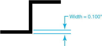
After you select the Width option, AutoCAD prompts you for a starting width and an ending width. This allows you to vary the width from point to point. To apply a width to all the line segments of a polyline, you simply specify an equal starting and ending width. For instance, to draw a polyline with a constant width of 0.100″, you type .1<Enter> when AutoCAD prompts you to Specify starting width<0.0000>:. AutoCAD then prompts you for the ending width of the polyline segment using the starting width as the default by prompting Specify ending width<0.1000>:. This allows you to simply press the <Enter> key to create a constant width. Figure 9-18 shows a polyline drawn with a constant width of 0.100″.
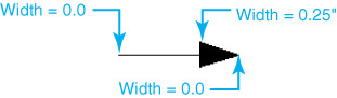
Varying a polyline width provides many unique possibilities. For instance, you can use a polyline with varying widths to create an arrow by specifying a starting width of 0.000″ to create the point, or tip, and then specifying an ending width greater than zero for the next point so the line is tapered. For instance, to create an arrow that tapers from a point to a base width of 0.25″, you would type 0<Enter> when AutoCAD prompts Specify starting width<0.0000>: to create the arrow point and then type .25<Enter> when AutoCAD prompts Specify ending width<0.1000>: to indicate the base width, as shown in Figure 9-19.
You can even combine these varying width techniques with polyline arcs to create curved arrows that can be used for signage on parking lot plans and roadways, as shown in Figure 9-20.

Exercise 9-4 Drawing Polylines with a Width
![]() Continue from Exercise 9-3.
Continue from Exercise 9-3.
![]() Create a polyline with a uniform width of 0.100″ similar to the polyline shown in Figure 9-18 using the PLINE command and the Width option.
Create a polyline with a uniform width of 0.100″ similar to the polyline shown in Figure 9-18 using the PLINE command and the Width option.
![]() Create a polyline arrow that tapers from a point to a base width of 0.25″ similar to the polyline shown in Figure 9-19 using the PLINE command and the Width option.
Create a polyline arrow that tapers from a point to a base width of 0.25″ similar to the polyline shown in Figure 9-19 using the PLINE command and the Width option.
![]() Create a curved polyline arrow similar to the polyline shown in Figure 9-20 using the PLINE command and the Width and Arc options.
Create a curved polyline arrow similar to the polyline shown in Figure 9-20 using the PLINE command and the Width and Arc options.
![]() Save the drawing.
Save the drawing.
Drawing Rectangles
The RECTANGLE or RECTANG command draws a polyline rectangle using two user-supplied corner points.
Rectangle |
|
Ribbon & Panel: |
Home | Draw
|
Menu: |
Draw | Rectangle |
Command Line: |
RECTANGLE or RECTANG |
Command Alias: |
None |

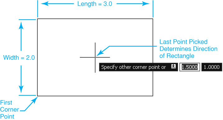
When you start the RECTANG command, AutoCAD prompts you to Specify first corner point or ![]() . You can either type in a coordinate value, or you can pick a point in your drawing. After you specify the first point, you can locate the other corner point as shown in Figure 9-21.
. You can either type in a coordinate value, or you can pick a point in your drawing. After you specify the first point, you can locate the other corner point as shown in Figure 9-21.
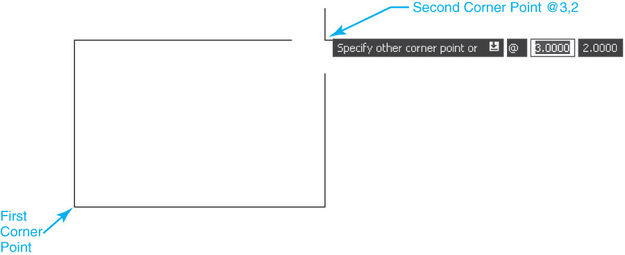
Remember that it is always possible to enter a coordinate value any time AutoCAD prompts you for a point. In fact, if you know the length and width of the rectangle, you can enter a relative coordinate where x is the length and y is the width. For instance, to draw a 3.000″ × 2.000″ rectangle, you can type @3,2<Enter> when AutoCAD prompts you to Specify other corner point or ![]() .
.
Tip
If you are using dynamic input, you do not need to use the @ prefix. The second pick point is relative by default.
Entering the Length and Width
The Dimensions option allows you to draw a rectangle by entering the length and width in response to AutoCAD prompts. To use the Dimensions option, you must pick the first corner point. After you enter a length and width, AutoCAD prompts you for a direction point by prompting Specify other corner point or ![]() . The point you pick determines the rectangle’s orientation, as shown in Figure 9-22.
. The point you pick determines the rectangle’s orientation, as shown in Figure 9-22.
Note
AutoCAD remembers the length and width dimensions you enter so the next time you draw a rectangle using the Dimensions option you can simply press <Enter> to draw a rectangle the same size.
Drawing a Rectangle at an Angle
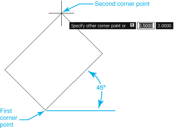
The Rotation option allows you to draw a rectangle at a user-specified angle. To use the Rotation option, you must pick the first corner point. You have three possible ways to input the rotation angle:
• Type the angle at the keyboard.
• Pick a point to define the angle using the first corner point as the base point.
• Use the Pick points option to pick two separate points to define the angle.
The first option requires that you enter the angle by typing it at the keyboard. For instance, to create a rectangle that is rotated 45°, you enter 45<Enter>. After you enter the angle, the rectangle preview changes to the input angle, and AutoCAD again prompts you to Specify other corner point or ![]() . You can locate the second corner point using any of the techniques explained in this section, including using the Dimensions and Area options, as shown in Figure 9-23.
. You can locate the second corner point using any of the techniques explained in this section, including using the Dimensions and Area options, as shown in Figure 9-23.
You can also pick a point to define the angle using the first corner point as the base point, or vertex. When picking a point to define the angle, it is usually beneficial to use either the Ortho Mode or Polar Tracking drawing tool.
The Pick points option gives you the ability to define the rotation angle using two separate points instead of using the first corner point as the default base point. After you select the Pick points option, AutoCAD prompts you for two pick points. After you pick the two points, the rectangle preview changes to the input angle, and AutoCAD again prompts you to Specify other corner point or ![]() . You can locate the second corner point using any of the techniques explained in this section.
. You can locate the second corner point using any of the techniques explained in this section.
Note
AutoCAD defaults to creating a rectangle at the same rotation angle the next time you use the command by displaying the current rotation angle at the command line:
Current rectangle modes: Rotation = 45
Drawing a Rectangle by Specifying the Area
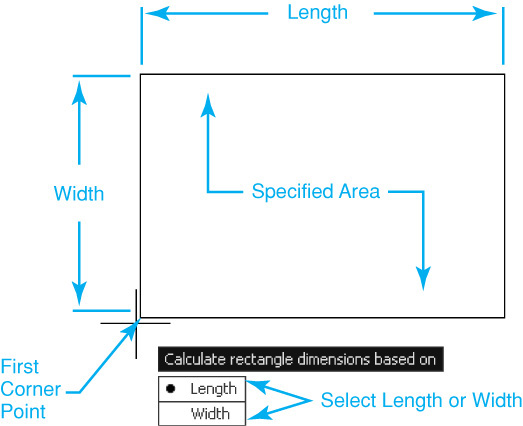
The Area option allows you to draw a rectangle by specifying its area and either the length or the width. To use the Area option, you must pick the first corner point. After you select the Area option, enter the desired area and press <Enter>. AutoCAD then asks you whether you want to specify the length or width. Select the desired option and after you enter the distance, AutoCAD draws the rectangle automatically at the first corner point location, as shown in Figure 9-24.
Exercise 9-5 Drawing Rectangles
![]() Continue from Exercise 9-4.
Continue from Exercise 9-4.
![]() Create a 3.000″ × 2.000″ rectangle similar to the rectangle shown in Figure 9-21 using the RECTANG command and relative coordinate entry.
Create a 3.000″ × 2.000″ rectangle similar to the rectangle shown in Figure 9-21 using the RECTANG command and relative coordinate entry.
![]() Create a 3.000″ × 2.000″ rectangle similar to the rectangle shown in Figure 9-22 in another location using the RECTANG command and the Dimensions option to input the length and width.
Create a 3.000″ × 2.000″ rectangle similar to the rectangle shown in Figure 9-22 in another location using the RECTANG command and the Dimensions option to input the length and width.
![]() Create a 3.000″ × 2.000″ rectangle at a 45° angle similar to the rectangle shown in Figure 9-23 in another location using the RECTANG command and the Angle option to input the 45° angle.
Create a 3.000″ × 2.000″ rectangle at a 45° angle similar to the rectangle shown in Figure 9-23 in another location using the RECTANG command and the Angle option to input the 45° angle.
![]() Save the drawing.
Save the drawing.
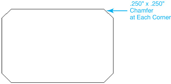
Chamfering Corners
The Chamfer option allows you to draw a rectangle with four beveled, or chamfered, corners using the specified distance from the corner point to the beginning of each chamfer.
chamfer: To cut off a corner with a slight angle or bevel.
After you select the Chamfer option, enter the distance for the first leg of the chamfer and press <Enter>. AutoCAD then prompts you to Specify second chamfer distance for rectangles<0.2500>: using the first distance as the default. Typically, you want to simply press <Enter> to accept the default and create a rectangle with 45° chamfers, although you can specify a different distance. After entering the chamfer distances, you can create a rectangle with chamfered corners using any of the techniques already explained. Figure 9-25 shows a 3.000″ × 2.000″ rectangle drawn with .250″ × .250″ chamfered corners.
Note
AutoCAD defaults to creating a rectangle with chamfered corners the next time you use the command by displaying the current chamfer distances at the command line:
Current rectangle modes: Chamfer = 0.2500 × 0.2500
Rounding Corners
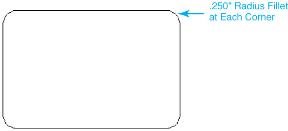
The Fillet option allows you to draw a rectangle with four rounded, or filleted, corners using the specified radius from the corner point.
fillet: To round off an inside or outside corner at a specific radius.
After you select the Fillet option, enter the radius and press <Enter>. After entering the radius, you can create a rectangle using any of the techniques explained above. Figure 9-26 shows a 3.000″ × 2.000″ rectangle drawn with .250″ filleted corners.
Note
AutoCAD defaults to creating a rectangle with filleted corners the next time you use the command by displaying the current fillet radius at the command line:
Current rectangle modes: Fillet = 0.2500
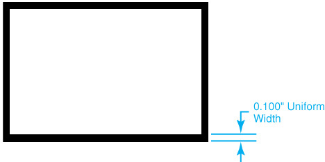
Drawing a Rectangle with a Width
The Width option allows you to draw a rectangle with a user-specified polyline width as explained earlier in the section “Drawing Polylines with a Width.”
After you select the Width option, enter the line width and press <Enter>. After entering the width, you can create a rectangle using any of the techniques explained previously. Figure 9-27 shows a 3.000″ × 2.000″ rectangle drawn with a 0.100″ uniform line width.
Note
AutoCAD defaults to creating a rectangle with a width the next time you use the command by displaying the current line width at the command line:
Current rectangle modes: Width = 0.1000
Exercise 9-6 Drawing Rectangles with Chamfered and Rounded Corners
![]() Continue from Exercise 9-5.
Continue from Exercise 9-5.
![]() Draw a 3.000″ × 2.000″ rectangle with .250″ × .250″ chamfered corners similar to the rectangle shown in Figure 9-25 using the RECTANG command and the Chamfer option.
Draw a 3.000″ × 2.000″ rectangle with .250″ × .250″ chamfered corners similar to the rectangle shown in Figure 9-25 using the RECTANG command and the Chamfer option.
![]() Draw a 3.000″ × 2.000″ rectangle in another location with .250″ rounded corners similar to the rectangle shown in Figure 9-26 using the RECTANG command and the Fillet option.
Draw a 3.000″ × 2.000″ rectangle in another location with .250″ rounded corners similar to the rectangle shown in Figure 9-26 using the RECTANG command and the Fillet option.
![]() Draw a 3.000″ × 2.000″ rectangle with a 0.100″ uniform width similar to the rectangle shown in Figure 9-27 using the RECTANG command and the Width option.
Draw a 3.000″ × 2.000″ rectangle with a 0.100″ uniform width similar to the rectangle shown in Figure 9-27 using the RECTANG command and the Width option.
![]() Save the drawing.
Save the drawing.
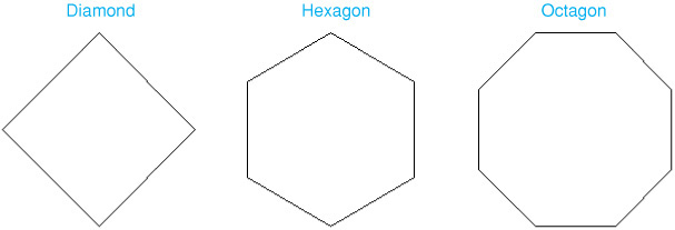
Drawing Polygons
The POLYGON command draws a polyline polygon with a user-supplied number of sides. See Figure 9-28.
Polygon |
|
Ribbon & Panel: |
Home | Draw
|
Menu: |
Draw | Polygon |
Command Line: |
POLYGON |
Command Alias: |
POL |

When you start the POLYGON command, AutoCAD prompts you to Enter number of sides<4>:. You can enter a number between 3 and 1024. The length of the sides is determined either by specifying a center point and a radius or by indicating the length of a typical side, called the edge. The default is to specify a center point and radius; the radius indicates a circle that either inscribes or circumscribes the polygon, and the length of the sides is generated automatically.
After you specify the number of sides, AutoCAD prompts you to Specify center of polygon or ![]() . The default is to locate a center point either by picking a point or by typing in a coordinate value. AutoCAD then asks you whether you want to create the polygon inscribed inside a circle (see Figure 9-29A) with the specified radius or circumscribed on the outside of the circle (see Figure 9-29B) by prompting Enter an option
. The default is to locate a center point either by picking a point or by typing in a coordinate value. AutoCAD then asks you whether you want to create the polygon inscribed inside a circle (see Figure 9-29A) with the specified radius or circumscribed on the outside of the circle (see Figure 9-29B) by prompting Enter an option ![]() . After selecting either option, AutoCAD then prompts you to Specify radius of circle:. You can either type a radius at the keyboard or pick a point as shown in Figures 9-29A and B.
. After selecting either option, AutoCAD then prompts you to Specify radius of circle:. You can either type a radius at the keyboard or pick a point as shown in Figures 9-29A and B.
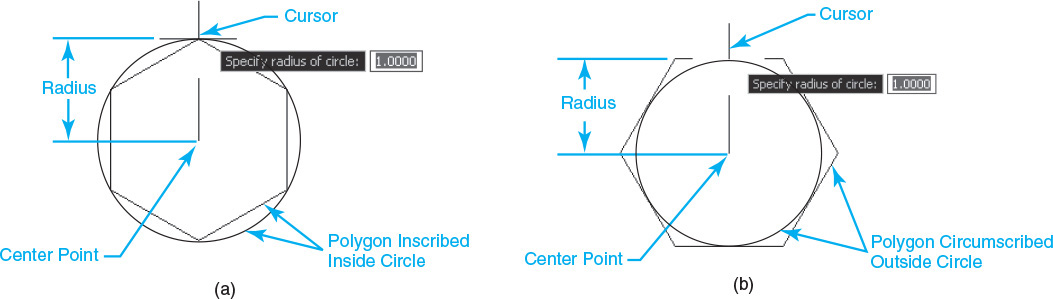
Figure 9-29 A Polygon with six sides inscribed in a circle B Polygon with six sides circumscribed outside a circle
Specifying the Length of a Side
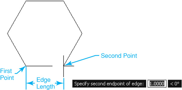
The Edge option allows you to create a polygon by specifying the location and length of a side. AutoCAD uses the input length to automatically create the remaining specified number of sides.
After you select the Edge option, you can either pick a point or type in a coordinate value to locate the starting point of one of the sides. AutoCAD then prompts Specify second endpoint of edge:. The second point determines the length for all the sides specified and the rotation angle of the finished polygon, as shown in Figure 9-30.
AutoCAD remembers the number of sides you enter so the next time you draw a polygon you can simply press <Enter> to draw a polygon with the same number of sides.
Tip
You can specify the second edge point using absolute, relative, or polar coordinate entry methods. It is also possible to use direct distance entry with either the Ortho Mode or Polar Tracking drawing tool.
![]() Continue from Exercise 9-6.
Continue from Exercise 9-6.
![]() Draw a six-sided polygon inscribed inside a circle with a radius of 1.000″ similar to the polygon shown in Figure 9-29A using the POLYGON command.
Draw a six-sided polygon inscribed inside a circle with a radius of 1.000″ similar to the polygon shown in Figure 9-29A using the POLYGON command.
![]() Next to the polygon created in step 2, draw a six-sided polygon circumscribed outside a circle with a radius of 1.000″ similar to the polygon shown in Figure 9-29B using the POLYGON command.
Next to the polygon created in step 2, draw a six-sided polygon circumscribed outside a circle with a radius of 1.000″ similar to the polygon shown in Figure 9-29B using the POLYGON command.
![]() Next to the polygon created in step 3, draw a six-sided polygon with an edge length of 0.500″ similar to the polygon shown in Figure 9-30 using the POLYGON command and the Edge option.
Next to the polygon created in step 3, draw a six-sided polygon with an edge length of 0.500″ similar to the polygon shown in Figure 9-30 using the POLYGON command and the Edge option.
![]() Save the drawing.
Save the drawing.
Drawing Donuts
The DONUT command draws a ring, or donut, with a user-specified inside diameter and outside diameter. The ring thickness equals the outside diameter minus the inside diameter. See Figure 9-31.
Donut |
|
Ribbon & Panel: |
Home | Draw
|
Menu: |
Draw | Donut |
Command Line: |
DONUT |
Command Alias: |
DO |

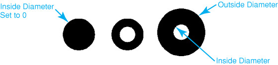
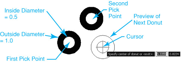
When you start the DONUT command, AutoCAD prompts you to Specify inside diameter of donut<0.5000>:. Enter a diameter greater than or equal to zero and press <Enter>. AutoCAD then prompts you to Specify outside diameter of donut<1.0000>:. Enter a value greater than the inside diameter and press <Enter>. AutoCAD repeatedly prompts you to Specify center of donut or<exit>: so you can locate multiple donuts, as shown in Figure 9-32.
Tip
Specifying an inside diameter equal to 0 creates a solid filled circle with the specified outside diameter.
![]() Continue from Exercise 9-7.
Continue from Exercise 9-7.
![]() Create some donuts with an inside diameter of 0.500″ and an outside diameter of 1.000″ using the DONUT command.
Create some donuts with an inside diameter of 0.500″ and an outside diameter of 1.000″ using the DONUT command.
![]() Create some solid donuts with an inside diameter of 0.000″ and an outside diameter of 1.000″ using the DONUT command.
Create some solid donuts with an inside diameter of 0.000″ and an outside diameter of 1.000″ using the DONUT command.
![]() Save the drawing.
Save the drawing.
Drawing Revision Clouds
The REVCLOUD command draws a polyline of sequential arcs to form a cloud shape that can be used as a revision cloud on a drawing to highlight markups and changes (see Figure 9-33).
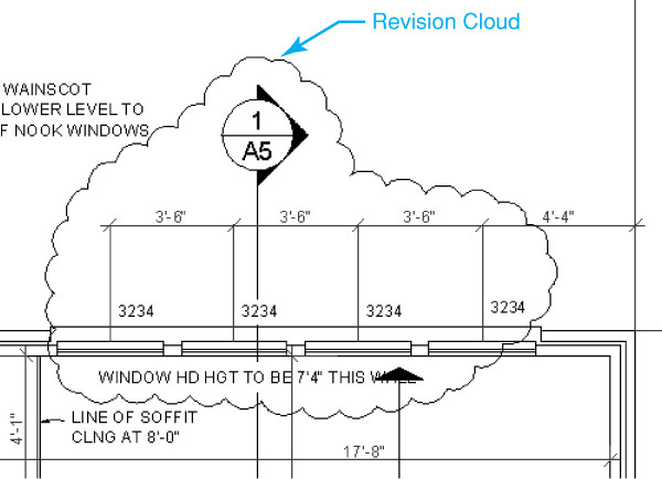
revision cloud: Continuous line made from arcs to resemble a cloud that is used to highlight markups and changes.
Revision Cloud |
|
Ribbon & Panel: |
Home | Draw
|
Menu: |
Draw | Revision Cloud |
Command Line: |
REVCLOUD |
Command Alias: |
None |

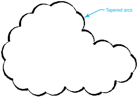
There are two different styles for a revision cloud: Normal and Calligraphy. The default style, Normal, draws the revision cloud using regular polyline arcs with no thickness. The Calligraphy style tapers the polyline arc thickness so the revision cloud looks as though it were drawn with a calligraphy pen.
When you start the REVCLOUD command, AutoCAD displays the default settings at the command line as follows:
Minimum arc length: 0.5000 Maximum arc length: 0.5000 Style: Normal
To create a revision cloud using the default settings, pick a point with your mouse and guide your mouse along the desired revision cloud path when AutoCAD prompts you to Specify start point or ![]() . You do not need to hold the mouse button down. Simply drag the mouse to create the clouded area. When your cursor position returns to the beginning point of the first arc, the revision cloud is closed automatically, as shown in Figure 9-34.
. You do not need to hold the mouse button down. Simply drag the mouse to create the clouded area. When your cursor position returns to the beginning point of the first arc, the revision cloud is closed automatically, as shown in Figure 9-34.
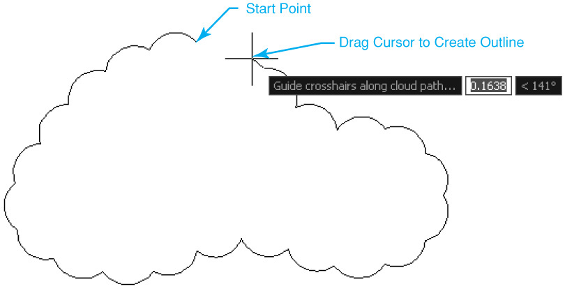
AutoCAD interactively flips the arc direction based on the direction you drag your mouse after specifying the start point so that the arc bulge faces the proper way.
Changing the Arc Length
The Arc length option allows you to change the minimum and maximum arc length used to create the polyline arcs when the revision cloud is being drawn so that you can make them bigger or smaller.
After you select the Arc length option, enter the desired minimum length and press <Enter>. AutoCAD prompts you to Specify maximum length of arc<0.5000>:. Enter the desired maximum length, and press <Enter>. The values become the default the next time you use the REVCLOUD command.
Note
AutoCAD accounts for the drawing scale factor by multiplying the minimum and maximum arc lengths by the current dimension scale factor, which is set via the Dimension Style Manager or the DIMSCALE system variable.
For More Details
See page 525 in Chapter 13 for more information about setting the dimension scale factor. See page 8 in Chapter 1 for more information about the drawing scale factor.
Switching Styles
The Style option allows you to switch between the Normal style and the Calligraphy style. Figure 9-35 shows a revision cloud drawn using the Calligraphy style.
Creating Revision Clouds from Existing Objects
You can convert existing objects such as a circles, ellipses, and polylines into a revision cloud using the Object option. After selecting the Object option, select the object you want to convert. After converting the object, AutoCAD allows you simply to change the direction of the arcs so they face in or out.
Tip
You can control whether the existing object is deleted after it is converted into a revision cloud via the DELOBJ system variable. Setting DELOBJ to 1 deletes the original object and setting DELOBJ to 0 maintains the original object.
Exercise 9-9 Drawing Revision Clouds
![]() Continue from Exercise 9-8.
Continue from Exercise 9-8.
![]() Create a revision cloud using the Calligraphy style similar to the one shown in Figure 9-35 using the REVCLOUD command and the Style option.
Create a revision cloud using the Calligraphy style similar to the one shown in Figure 9-35 using the REVCLOUD command and the Style option.
![]() Create a circle using the CIRCLE command.
Create a circle using the CIRCLE command.
![]() Convert the circle to a revision cloud using the REVCLOUD command and the Object option.
Convert the circle to a revision cloud using the REVCLOUD command and the Object option.
![]() Save the drawing.
Save the drawing.
Editing Polylines
You can edit polylines after they are created using the PEDIT command. The PEDIT command allows you to:
• Convert lines and arcs to polylines
• Close and open polylines
• Join multiple polylines together
• Change a polyline’s width
• Edit polyline vertices so that you can move, add, and remove points
• Curve fit a polyline
• Control a polyline’s linetype generation
• Reverse a polyline
Edit Polyline |
|
Ribbon & Panel: |
Home | Modify
|
Menu: |
Modify | Object | Polyline |
Command Line: |
PEDIT |
Command Alias: |
PE |

When you start the PEDIT command, AutoCAD prompts you to Select polyline or ![]() . You can then select a polyline, a line, or an arc. If you select an object that is not a polyline, AutoCAD displays the following at the command line so you can convert it:
. You can then select a polyline, a line, or an arc. If you select an object that is not a polyline, AutoCAD displays the following at the command line so you can convert it:
Object selected is not a polyline
AutoCAD allows you to convert the object by prompting Do you want to turn it into one? ![]() . The default is Yes so you can simply press <Enter> to convert the selected line or arc.
. The default is Yes so you can simply press <Enter> to convert the selected line or arc.
Tip
The PEDITACCEPT system variable allows you to suppress display of the Object selected is not a polyline prompt so that objects are automatically converted. Setting the PEDITACCEPT to 1 (on) suppresses the prompt. Setting PEDITACCEPT to 0 (off) turns the prompt back on.
You can edit multiple polylines using the Multiple option. You can use any of the selection options to select multiple objects. If any of the objects are not polylines, AutoCAD allows you to convert them using the same approach mentioned earlier.
After a polyline is selected, or converted, AutoCAD prompts you to Enter an option ![]() to allow you to select an editing option. All the PEDIT options are explored in the following sections.
to allow you to select an editing option. All the PEDIT options are explored in the following sections.
Closing and Opening Polylines
You can close or open a polyline using either the Close or Open option. The PEDIT command provides one option or the other depending on the polyline’s current open or closed status.
To close an open polyline so that a polyline segment is created between the first and last point, select the Close option. Figure 9-36 shows the result of selecting the Close option.
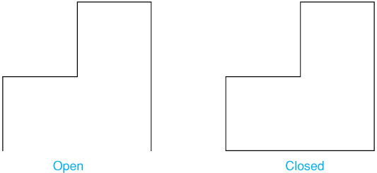
To open a closed polyline so that the polyline segment between the first and last point is removed, select the Open option.
Joining Polylines
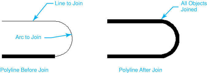
The Join option allows you to join a polyline, line, or arc to one or more open polylines either if their ends connect or if they are within a specified fuzz distance of each other.
fuzz distance: Distance used to determine whether polyline endpoints that are not connected can be connected by extending them or trimming them, or connecting them with a new polyline segment.
When you join objects using the Join option, the properties of the polyline selected first, including the polyline’s ending width, are inherited by all the objects that are successfully joined.
Applying a fuzz distance is available only when you use the Multiple option and is explained in detail in the following section. After you select the Join option, you can then use any of the selection options to select one or more connected objects and press <Enter> as shown in Figure 9-37.
AutoCAD reports the success or failure of the join attempt by displaying how many objects were added to the original polyline at the command line:
2 segments added to polyline
It is your job to determine whether all the objects were joined based on how many objects you originally selected. For instance, if you selected three objects and AutoCAD says that only two segments were added, you have a problem. You then have to inspect visually the endpoints of each object that was not joined and connect any points that are not connected. This can become a very tedious process with a complex join operation that consists of many objects. Luckily, we can use the fuzz distance mentioned earlier.
Joining Polylines That Do Not Meet
As mentioned earlier, you can join polylines, lines, and arcs whose endpoints are not connected but are within a specified fuzz distance of each other. AutoCAD will either extend, trim, or insert a line segment in order to create the connection. To enter a fuzz distance, you must use the Multiple option explained earlier to select the objects you want to join first. If you then select the Join option using the same methods explained earlier, AutoCAD prompts you to Enter fuzz distance or ![]() after you select the objects to join. You can then enter the distance you want to close and press <Enter>. AutoCAD displays how many segments were added at the command line in the same fashion as a regular join operation so you can determine whether all the objects were joined successfully.
after you select the objects to join. You can then enter the distance you want to close and press <Enter>. AutoCAD displays how many segments were added at the command line in the same fashion as a regular join operation so you can determine whether all the objects were joined successfully.
You can set the method that AutoCAD uses to join polylines via the Jointype option. After selecting the Jointype option, you can choose one of the following options:
• Extend Joins by extending or trimming the segments to the nearest endpoints
• Add Joins by adding a straight segment between the nearest endpoints
• Both Joins by extending or trimming if possible. Otherwise joins by adding a straight segment between the nearest endpoints
Tip
Joining a polyline removes the curve fitting from a curve fit polyline. Curve fitting polylines are explained later in this section.
Exercise 9-10 Joining Polylines Using PEDIT
![]() Start a new drawing using the acad.dwt drawing template.
Start a new drawing using the acad.dwt drawing template.
![]() Create the drawing shown in Figure 9-38 using only the LINE and ARC commands, making sure to connect all the line and arc segments.
Create the drawing shown in Figure 9-38 using only the LINE and ARC commands, making sure to connect all the line and arc segments.
![]() Join all the line and arc segments using the PEDIT command and the Join option.
Join all the line and arc segments using the PEDIT command and the Join option.
![]() Save the drawing as CH9_EXERCISE10.
Save the drawing as CH9_EXERCISE10.
Changing the Polyline Width
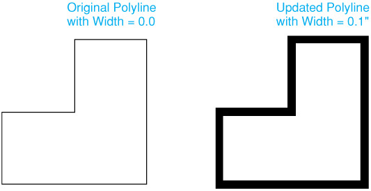
The Width option allows you to specify a new uniform width for all the polyline segments. After you select the Width option, enter the new uniform width and press <Enter> to change the width, as shown in Figure 9-39.
Tip
You can vary the width from point to point using the Properties palette. The Properties palette allows you to step through each vertex of a polyline and set its width property individually.
Exercise 9-11 Changing Polyline Width Using PEDIT
![]() Continue from Exercise 9-10.
Continue from Exercise 9-10.
![]() Change the polyline width to a uniform width of 0.100″ using the PEDIT command and the Width option.
Change the polyline width to a uniform width of 0.100″ using the PEDIT command and the Width option.
![]() Save the drawing.
Save the drawing.
Editing Polyline Vertices
The Edit vertex option allows you to edit a polyline’s vertex points individually so you can:
• Break one or more polyline segments
• Insert a vertex point
• Move a vertex point
• Regenerate the polyline
• Straighten two more polyline segments
• Attach a tangent direction
• Change the starting and ending width of a polyline segment
The Edit vertex option is considered a legacy option, and its use in editing vertex points is not recommended because of its complexity. Instead, it is suggested that you use multifunctional grips, which are discussed later in this chapter. They are much more user-friendly and easier to manipulate.
Converting Polylines into Smooth Curves
You can transform a polyline that is made up of straight line segments into a polyline with smooth curves using the Fit and Spline options. Both options allow you to curve fit a polyline with very different results.
curve fit: The process of adding vertex points to a straight line segment polyline in order to create a smooth curve.
After a polyline is curve fit using either option, it is possible to convert it back to straight polyline segments using the Decurve option. All the curve fit options are explained in detail in the following sections.
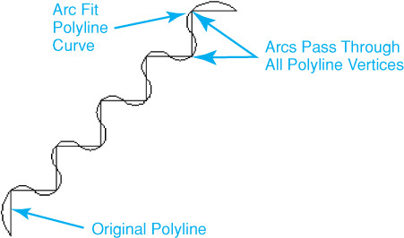
Fit Option
The Fit option creates an arc fit polyline. An arc fit polyline is a smooth curve consisting of arcs joining each pair of vertex points with the curve passing through all vertices of the polyline, as shown in Figure 9-40.
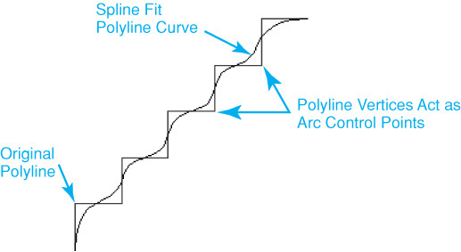
Spline Option
The Spline option uses the vertices of the selected polyline as the control points to create a curve approximating a B-spline, but it is not as accurate as a true spline.
B-spline: An approximate spline curve also referred to as a nonuniform rational B-spline, or NURBS, curve.
A spline fit polyline passes through the first and last polyline vertex points unless the original polyline was closed. The curve is pulled toward the other vertex points but does not pass through them, as shown in Figure 9-41. The more control points you specify, the more pull they exert on the curve.
Tip
Setting the SPLFRAME system variable to 1 (on) turns on the spline curve control point frame the next time the drawing is regenerated. AutoCAD draws both the frame and the spline curve. Setting SPLFRAME to 0 (off) turns off the spline curve control frame.
AutoCAD can generate either quadratic or cubic spline fit polylines. A cubic B-spline is very smooth, much smoother than a quadratic B-spline, as shown in Figure 9-42.
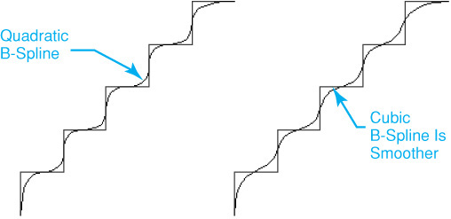
The default spline curve type is the smoother cubic B-spline. The SPLINETYPE system variable controls the type of spline curve created. Setting SPLINETYPE to 5 creates a quadratic B-spline. Setting SPLINETYPE to 6 creates a cubic B-spline.
Tip
You can also control the smoothness of a spline approximation via the Segments in a polyline curve setting in the Display Resolution area on the Display tab of the Options dialog box. This setting controls the number of line segments generated for each polyline curve. Setting this value higher means a greater number of line segments are drawn to create a more precise spline curve. The default value is 8. The maximumsetting is 32767.
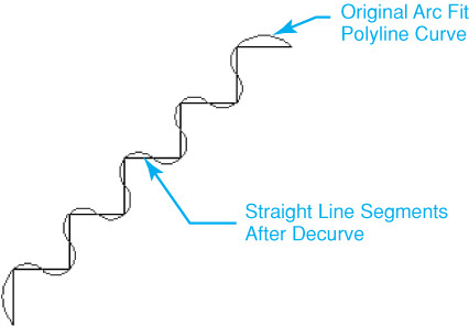
Decurve Option
The Decurve option removes extra points inserted by an arc fit or spline fit curve and straightens all the polyline segments back to their original straight line segments, as shown in Figure 9-43.
Tip
You cannot use the Decurve option after you edit a spline fit polyline with either the BREAK or TRIM command.
Exercise 9-12 Converting Polylines into Smooth Curves
![]() Continue from Exercise 9-11.
Continue from Exercise 9-11.
![]() Create an arc fit polyline similar to the polyline shown in Figure 9-40 using the PEDIT command and the Fit option.
Create an arc fit polyline similar to the polyline shown in Figure 9-40 using the PEDIT command and the Fit option.
![]() Create a cubic spline fit polyline in another location similar to the polyline shown in Figure 9-42 using the PEDIT command and the Spline option.
Create a cubic spline fit polyline in another location similar to the polyline shown in Figure 9-42 using the PEDIT command and the Spline option.
![]() Convert both curve fit polylines created in steps 2 and 3 back into straight line segments similar to those shown in Figure 9-43 using the PEDIT command and the Decurve option.
Convert both curve fit polylines created in steps 2 and 3 back into straight line segments similar to those shown in Figure 9-43 using the PEDIT command and the Decurve option.
![]() Save the drawing.
Save the drawing.
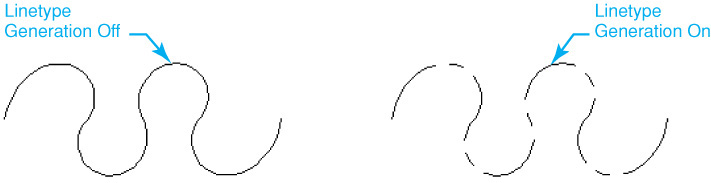
Controlling Polyline Linetype Generation
The Ltype gen option allows you to generate the polyline’s linetype definition in a continuous pattern through all the vertices of the polyline. When polyline linetype generation is turned off, the linetype definition is applied to each individual polyline segment so dashes, gaps, etc. are sometimes not displayed. Figure 9-44 shows a polyline with a CENTER linetype with linetype generation turned on and off.
Note
The Ltype gen option does not apply to polylines with tapered segments.
Reversing a Polyline
Sometimes it is necessary to reverse a polyline. For instance, if you are using any of the complex AutoCAD linetypes with words built into them like “GAS” or “HW,” the words sometimes appear upside down or in the wrong direction. The Reverse option allows you to reverse a polyline so that the first vertex point becomes the last vertex point, the last vertex point becomes the first, and all vertex points in-between reverse order.
Note
By default, when reversing a polyline that has varying segment widths, all segment widths are updated when using the Reverse option so the polyline maintains its original appearance.
Tip
The PLINEREVERSEWIDTHS system variable provides increased flexibility when reversing the direction of polylines that have varying widths. When PLINEREVERSEWIDTHS is set to 0 (default), the start and end of the polyline are reversed and the segments with varying widths are unaffected. When PLINEREVERSEWIDTHS is set to 1, the start and end of the polyline are reversed, and widths of the segments are applied to the vertices starting in the opposite direction.
Editing Polylines Using Grips
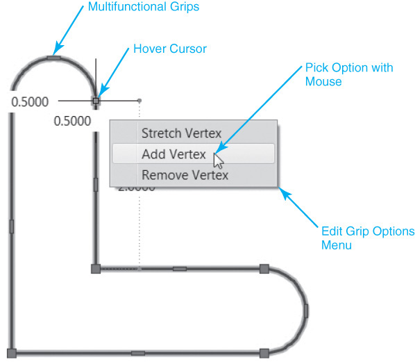
One of the easiest ways to edit polylines is to use multifunctional polyline grips. If you select an existing polyline with your cursor, you’ll see that, in addition to the familiar primary grips located at the end of each polyline segment, there are additional secondary grips located at each segment’s midpoint. These are multifunctional grips whose available functions can be seen by hovering your cursor over a grip to display a menu of options, like the one shown in Figure 9-45, that you can use your mouse to select from.
If you select a grip so that it is red (active), you can either cycle through the available functions by pressing the <Ctrl> key or choose one of the options from the menu by pressing the down arrow on your keyboard. Corresponding function icons appear next to the cursor in the AutoCAD drawing to indicate the active function.
To sub-select one or more segments of a polyline, hold down the <Ctrl> key while left-clicking on the polyline. Grip behavior for the sub-selected segments is the same as when an entire polyline is selected.
Exploding Complex Objects
You can explode any of the complex line objects discussed in this chapter and convert them into multiple individual line and arc segments using the EXPLODE command.
EXPLODE |
|
Ribbon & Panel: |
Home | Modify
|
Pull-down Menu: |
Modify | Explode |
Command Line: |
EXPLODE |
Command Alias: |
X |

When you start the EXPLODE command, AutoCAD prompts you to Select objects: so that you can select one or more complex objects.
If you select one or more objects that cannot be exploded, AutoCAD displays how many objects could not be exploded at the command line:
1 was not able to be exploded.
Note
When you explode a polyline with a width, all the associated width information is discarded, and the resulting lines and arcs follow the polyline’s centerline.
Tip
You can also explode other complex AutoCAD objects such as hatch objects, multiline text, dimensions, and blocks into their individual subobjects. These and other complex objects are discussed later in the text. Typically, it is wise not to explode complex objects unless it is absolutely necessary because it increases the amount of memory used by the drawing and makes editing drawing information more difficult.
Chapter Summary
This chapter explained how to create and edit the different complex polyline objects in AutoCAD. We learned that rectangles, polygons, donuts, and revision clouds are all constructed using polylines. We saw how it is possible for polylines to have a constant or varying width assigned to them so that you can create different visual effects.
We also explored different ways to edit a polyline after it has been created. The PEDIT command provides many of the necessary options but can be cumbersome to use, especially when editing point vertices. For this task, you should rely on a combination of the multifunctional grip editing tools and the Properties palette to get you through.
Finally, the EXPLODE command was introduced to show you that there is a way to break down complex polyline objects into individual line segments and arcs. It was also pointed out that this command should be used sparingly because it adds unnecessary data to your drawings and makes it harder to edit information later.
Chapter Test Questions
Multiple Choice
Circle the correct answer.
1. Complex line objects can be used for which of the following purposes?
a. Drawing contour lines
b. Calculating areas
c. Drawing roadways
d. All of the above
2. The command that breaks a complex line object down into individual lines and arcs is:
a. ERASE
b. EXPLODE
c. EXTEND
d. None of the above
3. The system variable that controls whether an old-format polyline is created or a new optimized polyline is created when you use the PLINE command is named:
a. PLTYPE
b. PLINEWID
c. PLINETYPE
d. PTYPE
4. By default, the polyline arcs created using the PLINE command’s Arc option are:
a. Created using three points
b. Created using two points
c. Tangent
d. b and c
5. To create a clockwise polyline arc using the Angle option, you can:
a. Enter an angle greater than 360°
b. Enter an angle less than 0°
c. Pick a point
d. Change the base angle
6. You can use polyline widths to create:
a. Arrowheads
b. Road signs
c. Border lines
d. All of the above
7. You can draw a polyline rectangle with the RECTANG command by:
a. Picking points
b. Entering a length and width
c. Specifying the total area and one side length
d. All of the above
8. To draw a solid donut when using the DONUT command, specify an inside diameter:
a. Greater than the outside diameter
b. That is negative
c. Of 0.000″
d. Of 1.000″
9. The system variable that allows you to suppress the Object selected is not a polyline prompt when converting an arc or line into a polyline using the PEDIT command is named:
a. PEDITACCEPT
b. ACCEPTPEDIT
c. PLINEDIT
d. APEDIT
10. The maximum gap size that objects can be apart and still be joined using the PEDIT command’s Join option is called:
a. Join distance
b. Fuzz distance
c. Max gap
d. Join gap
Matching
Write the number of the correct answer on the line.
1. True or False: Polylines can be used to calculate an enclosed area.
2. True or False: There are two different types of polylines.
3. True or False: Entering a negative angle when using the polyline arc Angle option creates a counterclockwise arc.
4. True or False: It is possible to create polylines that have a varying width from vertex point to vertex point.
5. True or False: Turning off the Show/Hide Lineweight button on the AutoCAD status bar turns off all polyline widths.
6. True or False: It is possible to draw a rectangle by specifying its total area.
7. True or False: You must specify a negative inside diameter to draw a solid (filled) donut using the DONUT command.
8. True or False: It is possible to join multiple objects together into one continuous polyline even when all the objects are not connected.
9. True or False: The PEDIT command’s Spline option can be used to create a true B-spline.
10. True or False: It is possible to convert a curve fitted polyline back into its original straight line segments.
1. Start a new drawing using the acad.dwt template. Set the grid spacing to .1, the snap spacing to .025, and turn both the grid display and Snap mode on.
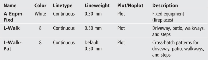
2. Create the following layers:
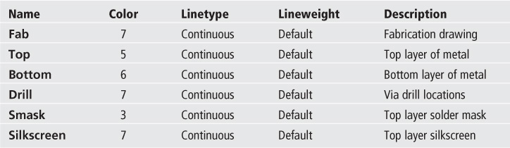
3. With Snap mode turned on, draw the parts shown in Figure 9-46. Each round pad consists of a 0.060″-diameter circle on the Top layer, a 0.020″-diameter circle on the Drill layer, and another 0.060″-diameter circle on the Bottom layer. The center of each pad should be placed on a grid point.
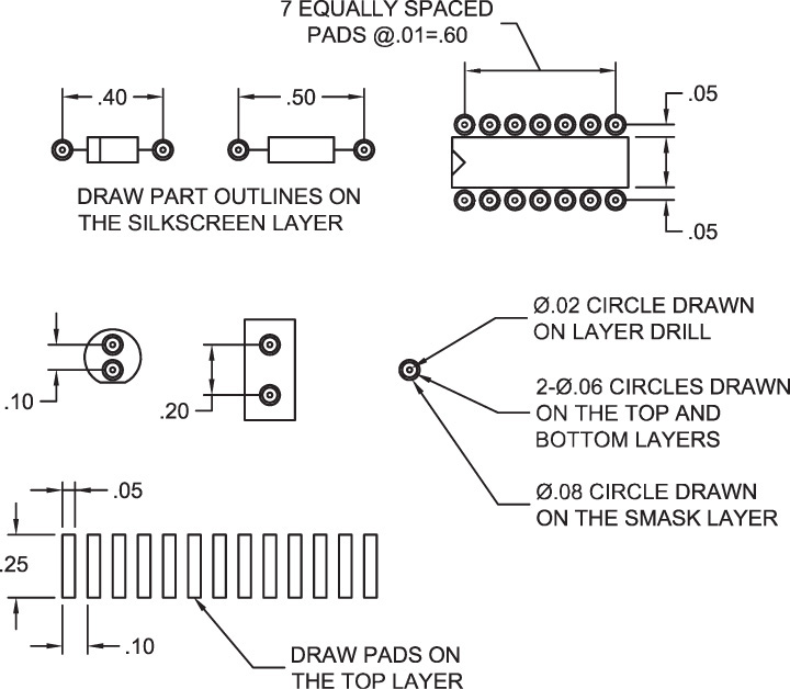
4. Create the board outline and move and copy the parts to arrange them as shown in Figure 9-47.
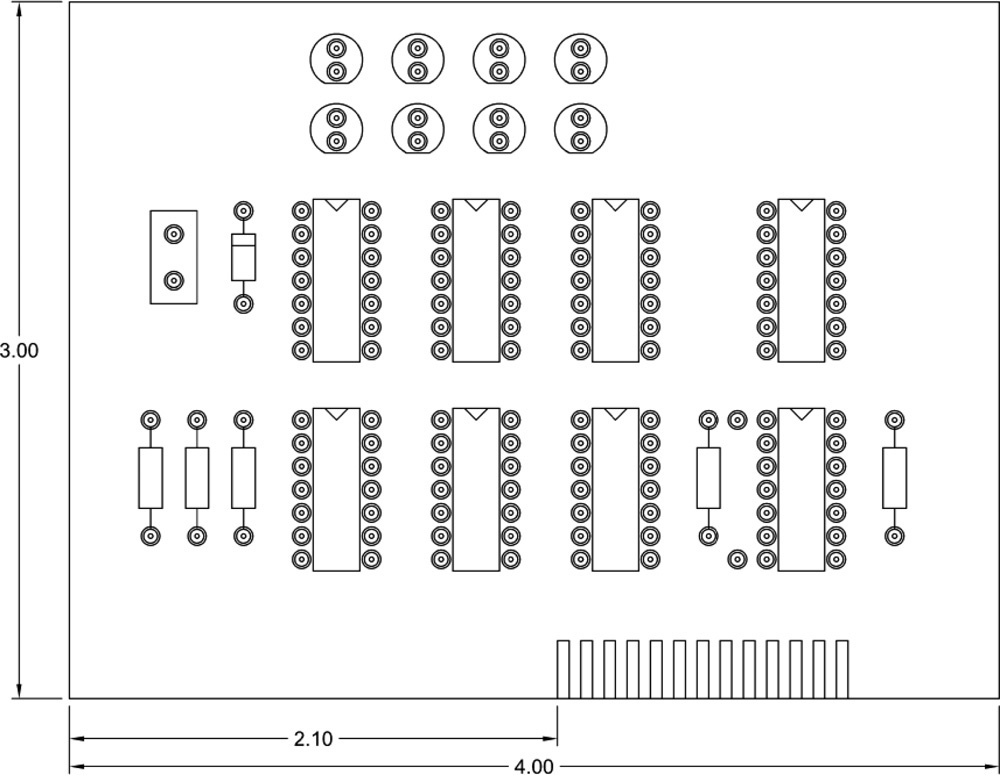
5. Using polylines, draw the wiring on the Top layer as shown in Figure 9-48. Use a polyline width of 0.006″. All points should be placed on snap coordinates.
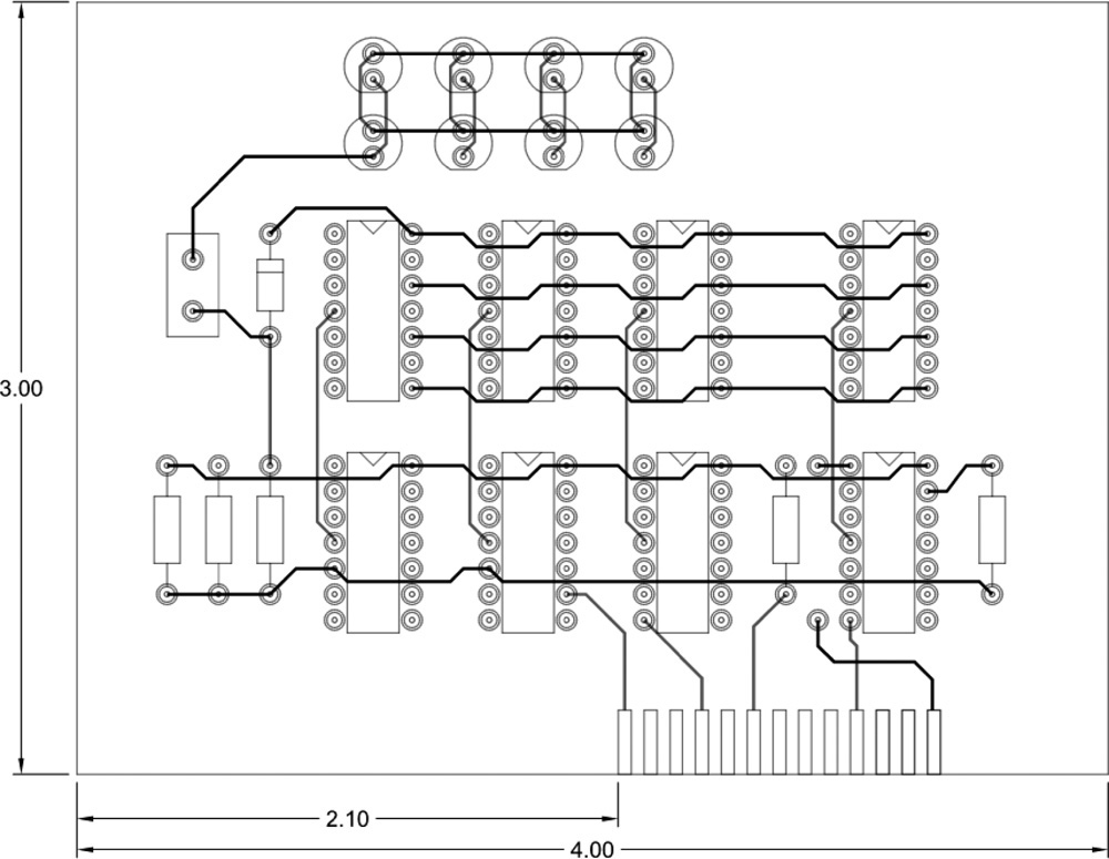
6. Do not draw text or dimensions.
7. Save your drawing as P9-1.
![]() Project 9-2: Logo [INTERMEDIATE]
Project 9-2: Logo [INTERMEDIATE]
1. Start a new drawing using the acad.dwt template.
2. Create the logo shown in Figure 9-49 using polyline objects. Do not draw dimensions.
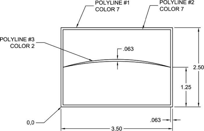
3. Save your drawing as P9-2.
![]() Project 9-3: Architectural D-Size Border, continued from Chapter 6 [ADVANCED]
Project 9-3: Architectural D-Size Border, continued from Chapter 6 [ADVANCED]
1. Open the template file Architectural D-Size.DWT from Chapter 6.
2. Create the logo outline and graphic scale outlines as shown in Figure 9-50 using polylines and a circle on the layer A-Anno-Ttlb-Logo. Do not draw dimensions.
3. Save the drawing to a template file as Architectural D-Size.DWT.
![]() Project 9-4: Window Extrusion—Metric [BASIC]
Project 9-4: Window Extrusion—Metric [BASIC]
1. Start a new drawing using the acadiso.dwt template.
2. Create the following layers:
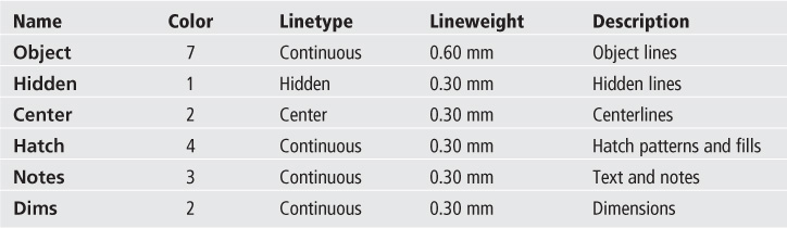
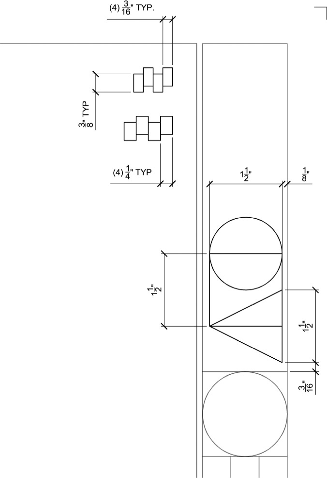
3. Draw the window extrusion as shown in Figure 9-51 using a single polyline on layer Object.
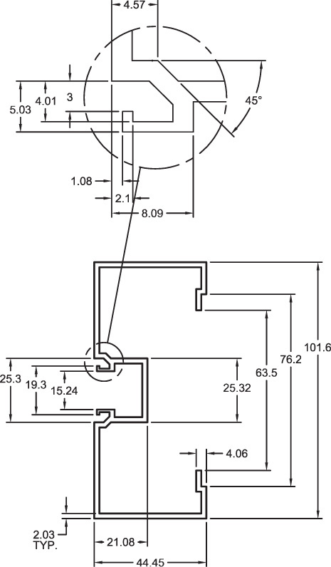
4. Do not draw enlarged detail in circle at top.
5. Do not include notes or dimensions.
6. Save the drawing as P9-4.
![]() Project 9-5: Residential Architectural Plan, continued from Chapter 8 [ADVANCED]
Project 9-5: Residential Architectural Plan, continued from Chapter 8 [ADVANCED]
1. Open drawing P8-5 from Chapter 8.
2. Create the following layers:
3. Draw the patio and driveway as shown in Figure 9-52 using spline fit polylines. Use appropriate layers for all objects.
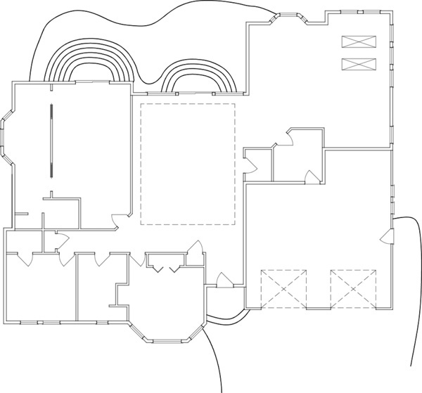
4. Save your drawing as P9-5.