Chapter 9. Manufacturing
Business imperatives are changing for every industry, and manufacturing is no exception. Controlling costs and improving efficiency have always been important to manufacturers, but as industry models change and competition heats up, the primary focus is now shifting toward innovation and improved business models. After decades of squeezing costs out of production systems and the supply chain, manufacturers are recognizing that further cost containment may only impede customer service and open the door to competition.
These economic changes are igniting a massive disruption in the manufacturing industry, led by advances in digitization and IoT. This chapter explores these disruptive forces and looks at innovative architectures that are being used to digitize factories and connect machines. This chapter includes the following sections:
![]() An Introduction to Connected Manufacturing: The chapter opens by examining the technologies that are creating digital disruption in manufacturing. This section also discusses a strategy for the connected factory and the business benefits to manufacturers.
An Introduction to Connected Manufacturing: The chapter opens by examining the technologies that are creating digital disruption in manufacturing. This section also discusses a strategy for the connected factory and the business benefits to manufacturers.
![]() An Architecture for the Converged Factory: Industrial automation and control systems (IACS) networking technologies are converging, with the aid of Ethernet and IP. This section explores a connected factory framework, with a focus on the Converged Plantwide Ethernet (CPwE) architecture that was jointly developed by Cisco and Rockwell Automation.
An Architecture for the Converged Factory: Industrial automation and control systems (IACS) networking technologies are converging, with the aid of Ethernet and IP. This section explores a connected factory framework, with a focus on the Converged Plantwide Ethernet (CPwE) architecture that was jointly developed by Cisco and Rockwell Automation.
![]() Industrial Automation Control Protocols: This section discusses the wide variety of networking and control protocols used in manufacturing, including EtherNet/IP, PROFINET, and Modbus/TCP.
Industrial Automation Control Protocols: This section discusses the wide variety of networking and control protocols used in manufacturing, including EtherNet/IP, PROFINET, and Modbus/TCP.
![]() Connected Factory Security: This section examines key security considerations in the connected factory and how they can be addressed with the correct design methodology.
Connected Factory Security: This section examines key security considerations in the connected factory and how they can be addressed with the correct design methodology.
![]() Edge Computing in the Connected Factory: The data generated by connected machines is massive. This section examines ways to implement edge computing in the connected factory to improve data management and visibility.
Edge Computing in the Connected Factory: The data generated by connected machines is massive. This section examines ways to implement edge computing in the connected factory to improve data management and visibility.
An Introduction to Connected Manufacturing
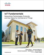
In a recent SCM World survey of more than 400 manufacturing business leaders, approximately 80% of participants stated that their top challenges were to meet customer delivery dates and respond to unforeseen events.1 Figure 9-1 shows the results of this survey.
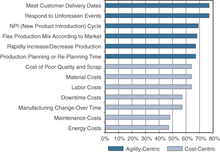
Figure 9-1 Shifting Focus from Cost to Agility
Source: SCM World /Cisco, Smart Manufacturing and the Internet of Things 2015 Survey of 418 Manufacturing Business Line and Executives and Plant Managers Across 17 Vertical Industries.
In a dynamic economy, manufacturers recognize the need to quickly turn around projects. They require the ability to scale, align, and adjust production capacities quickly in response to market demands. All too often, however, between economic fluctuations and long cycles of asset investment, manufacturers are saddled with aging production facilities that encumber and reduce their flexibility. For example, it is estimated that the average age of automation infrastructure in the United States is the highest it has been since 1938. Nearly 75% of US plants are more than 20 years old. Factories around the world are facing a similar challenge: Their aging assets not only slow innovation but also cost billions in unplanned downtime.
Connecting previously unconnected machines to intelligent data systems and, in turn, using the data generated by machines to better utilize existing investments in a more productive way is seen as the “low-hanging fruit” of factory modernization. The opportunity in front of manufacturers is massive. By some estimates, there are 60 million machines in factories throughout the world. Of them, 90% are not connected, and the vast majority of the machines are more than 15 years old.2–4 There is an increasing urgency to connect these machines and better utilize the data they generate.
At the heart of the manufacturing digital disruption are several IoT-related technologies:
![]() Data-driven manufacturing: Big data is changing the face of manufacturing. Manufacturers want access to all data generated from machines to monitor real-time quality control, improve overall equipment effectiveness (OEE), and reduce unplanned downtime. OEE is a well-known metric that indicates manufacturing productivity. Manufacturers are also exploring ways to use this data to support rapid retooling when market fluctuations or other needs occur.
Data-driven manufacturing: Big data is changing the face of manufacturing. Manufacturers want access to all data generated from machines to monitor real-time quality control, improve overall equipment effectiveness (OEE), and reduce unplanned downtime. OEE is a well-known metric that indicates manufacturing productivity. Manufacturers are also exploring ways to use this data to support rapid retooling when market fluctuations or other needs occur.
![]() OT and IT convergence: In the context of IoT in a factory setting, operational technology is made up of programmable logic controllers (PLCs), computers, and other technology that is often like the technology used in IT but is operated and owned by business operations outside IT. IP networking is enabling closer integration between machines and factories, and the line between factory and enterprise networks is becoming less distinct. Manufacturers are moving beyond traditional silos and looking for ways to bring their operations together under a single networking infrastructure. (For more information on OT and IT convergence, see Chapter 1, “What Is IoT?”)
OT and IT convergence: In the context of IoT in a factory setting, operational technology is made up of programmable logic controllers (PLCs), computers, and other technology that is often like the technology used in IT but is operated and owned by business operations outside IT. IP networking is enabling closer integration between machines and factories, and the line between factory and enterprise networks is becoming less distinct. Manufacturers are moving beyond traditional silos and looking for ways to bring their operations together under a single networking infrastructure. (For more information on OT and IT convergence, see Chapter 1, “What Is IoT?”)
![]() Improved technology with lower costs: New technologies are creating conditions for scaled, automated, and platform-based machine connectivity, monitoring, and optimization. In this evolved technology state, machine operations can be viewed as part of a fully connected network system instead of an air-gapped point system. The convergence of compute, switching, routing, and security has the potential to drive down the cost of connecting machines.
Improved technology with lower costs: New technologies are creating conditions for scaled, automated, and platform-based machine connectivity, monitoring, and optimization. In this evolved technology state, machine operations can be viewed as part of a fully connected network system instead of an air-gapped point system. The convergence of compute, switching, routing, and security has the potential to drive down the cost of connecting machines.
![]() Machine builder OEMs focused on new priorities: Original equipment manufacturers (OEMs) are facing disruption by new cloud-based providers that intend to provide Machines as a Service (MaaS), where machines can be deployed quickly on the plant floor through zero-touch deployment from the cloud, which offers remote connectivity and monitoring of those machines. This is driving a new focus on providing better customer experience and emphasizing after-sales products and services. Manufacturers are looking toward near 100% uptime and zero-touch deployments. They are also exploring ways to control support costs through remote connectivity and monitoring.
Machine builder OEMs focused on new priorities: Original equipment manufacturers (OEMs) are facing disruption by new cloud-based providers that intend to provide Machines as a Service (MaaS), where machines can be deployed quickly on the plant floor through zero-touch deployment from the cloud, which offers remote connectivity and monitoring of those machines. This is driving a new focus on providing better customer experience and emphasizing after-sales products and services. Manufacturers are looking toward near 100% uptime and zero-touch deployments. They are also exploring ways to control support costs through remote connectivity and monitoring.
An IoT Strategy for Connected Manufacturing
How do manufacturers respond to the challenges of connecting their factories? The drive toward agility and mass customization requires drastic improvements in technology to factories that are aging due to decades of cost containment. Digital transformation requires embracing key information technology advances, many of which have already been proven and widely adopted in other industries.
Perhaps the most important trend in manufacturing is the ubiquity of software. The lines between software and hardware are increasingly being dissolved. Many things that previously required hardware in our daily lives can now be achieved with software. Remember answering machines? The little recording boxes with miniature cassette tapes used by answering machines now reside as software in your smart phone or cloud-based servers hosted by your service provider. The same is happening in industrial settings, and an increasing number of physical controls are now residing as software available through the human–machine interface (HMI). In some factories, the only remaining physical control is the emergency stop button. The advantage of software over hardware is that new features and software patches are more simply and cost-effectively managed.
We are now entering a world where machine builders remotely troubleshoot and repair a machine that is causing unplanned downtime by simply sending a software update to the machine. Moreover, through artificial intelligence (AI), machines are now able to self-diagnose problems. Issues are revealed several days before an interruption occurs, and the machine repairs itself through a software update during a planned maintenance window. According to Jeff Immelt, CEO of General Electric, “If you went to bed last night as an industrial company, you’re going to wake up today as a software and analytics company.”
Software analytics are also playing an essential role in enabling manufacturing improvements in agility and efficiency. Manufacturers need to have full visibility to key performance indicators (KPIs) that unify activities on the plant floor, in the enterprise, and across the supply chain. This real-time data collection and analysis is a major focus of IoT initiatives for leading manufacturers.
One recent study of manufacturing executives asked them to rank the barriers to achieving their IoT and digital manufacturing objectives.1 The top three barriers related to a lack of visibility to data and data access to the machine, plant floor, and supply chain. Figure 9-2 displays the full results from this survey.
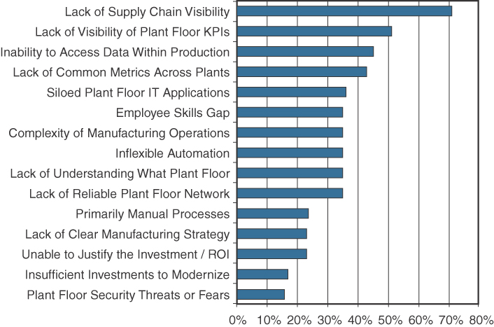
Figure 9-2 Primary barriers related to information visibility
Source: SCM World /Cisco, Smart Manufacturing and the Internet of Things 2015 Survey of 418 Manufacturing Business Line and Executives and Plant Managers Across 17 Vertical Industries.
Some have described a future state of manufacturing where factories won’t require any humans and will run “lights out.” In these factories, robotics and AI systems will fully automate production functions. All machines will be able to self-diagnose and self-repair. Pervasive analytics will be able to provide real-time visibility into all aspects of the production process and across the supply chain. All this will be enabled by software and an Ethernet-based connected factory infrastructure. We may be some years away from achieving this vision, but the technology foundations do exist today, and are now starting to be deployed in discrete manufacturing environments.
Note
In the world of manufacturing, there are generally two classes: discrete and process manufacturing. Discrete manufacturing refers to the production of distinct items, such as computers, fishing rods, and hand tools. Process manufacturing refers to the production of goods that are produced in bulk, such as foods, cement, and chemicals.
Business Improvements Driven Through IoT
The encouraging news for manufacturers is that, while technology and business models are changing dramatically, and the convergence of IT and OT production networks is inevitable, the same metrics that were the focus of business process improvements and quality efforts in the past are still in force with IoT and digital manufacturing initiatives today.
Note
An example of the manufacturing industry’s drive for quality is illustrated by the Six Sigma methodology. Six Sigma is a set of data-driven manufacturing techniques used to reduce defects. The name is taken from the goal of limiting any process to less than six standard deviations between the mean and nearest specification limit, aiming for a defect-free product 99.99966% of the time. The approach was first introduced by Bill Smith, an engineer working at Motorola, and was later a key focus of GE CEO Jack Welch. Six Sigma today is a set of tools and methods used for constant quality improvement.
Manufacturers are expecting profound improvements in key manufacturing metrics as visibility increases through improved connectivity to assets in the factory and across the enterprise. Improvements include reduced unplanned downtime, improved quality, and improved OEE.
In one case where a leading robot manufacturer implemented a real-time data analysis and predictive maintenance application for a leading auto manufacturer, unplanned downtime on several thousand robots was completely eliminated. This saved the manufacturer approximately $40 million in downtime in just a few weeks. Examples like this are leading to raised expectations of what is possible through the digital transformation of manufacturing.
An Architecture for the Connected Factory
In the past, traditional factory networks were deployed ad hoc. They were isolated and air-gapped from the enterprise IT network. In addition, network security in the factory was typically limited to an industrial DMZ, leaving the machines mostly unprotected. Factories rarely deployed network-level security systems that included identity policies and secure remote access tools that allowed plant-level data to be securely extended to the cloud. This is starting to change. Companies are beginning to tie together their industrial automation and control systems (IACS) with IT applications and analytics tools to provide control and analytics capabilities that are driving operational and business benefits.
CPwE is an architectural framework that provides network services to IACS devices and equipment and promotes secure integration into the enterprise network. Before the CPwE framework can be discussed in detail, it is important to define several key terms and review the IACS reference model, which CPwE heavily leverages.
Industrial Automation and Control Systems Reference Model
For several decades, manufacturing environments have relied on many different types of technologies to enable communication in the plant. These often have depended on vendor-specific proprietary communications protocols, which have, in turn, required purpose-built and vendor-specific networks.
Today, Ethernet and IP have become the standard for IACS communication systems. The IACS reference model uses a logical framework to describe the network and security functions of the manufacturing system. Following the Purdue Model for Control Hierarchy developed in the 1990s by the Purdue University Consortium for Computer Integrated Manufacturing, the manufacturing industry segments devices and equipment into hierarchical functions. The Purdue Model for Control Hierarchy is discussed in Chapter 8, “Securing IoT.” The International Society of Automation (ISA99) Committee for Manufacturing and Control Systems Security (now IEC-26443) has identified a logical framework for manufacturing based on this hierarchy, shown in Figure 9-3.
Figure 9-3 The ISA99 / IEC-62443 IACS Logical Framework, Based on the Purdue Model for Control Hierarchy
The IACS logical framework identifies functional zones and levels of the manufacturing plant and defines operations at each level. (Note that the naming convention used here is “levels,” not “layers,” to avoid confusion with protocol stack models, such as the OSI model.) These zones are defined as follows:
![]() Safety zone: Systems in the safety zone are typically hard-wired and air-gapped from the IACS network. The safety system’s function in this zone is to provide an IACS shutdown (a “stop” button) in case of an emergency. You can think of this as a hardwired fail-safe used to protect personnel and equipment if a dangerous event occurs.
Safety zone: Systems in the safety zone are typically hard-wired and air-gapped from the IACS network. The safety system’s function in this zone is to provide an IACS shutdown (a “stop” button) in case of an emergency. You can think of this as a hardwired fail-safe used to protect personnel and equipment if a dangerous event occurs.
![]() Manufacturing zone: The manufacturing zone is composed of the cell/area zones (Levels 0–2) and site-level manufacturing (Level 3) activities. The manufacturing zone is important because all IACS applications, devices, and controllers critical to monitoring and controlling plant IACS operations are here. To support secure plant operations and functioning of the IACS applications, there is a secure separation of the manufacturing zone and the enterprise zone (Levels 4 and 5).
Manufacturing zone: The manufacturing zone is composed of the cell/area zones (Levels 0–2) and site-level manufacturing (Level 3) activities. The manufacturing zone is important because all IACS applications, devices, and controllers critical to monitoring and controlling plant IACS operations are here. To support secure plant operations and functioning of the IACS applications, there is a secure separation of the manufacturing zone and the enterprise zone (Levels 4 and 5).
![]() Cell/area zone: The cell/area zone is the machine area within a plant. There are typically multiple cell/area zones within a single plant. For example, in an electronics plant, a cell/area may be the assembly process area. The cell/area zone might consist of just a single controller and associated devices, or it could be many controllers on a large assembly line.
Cell/area zone: The cell/area zone is the machine area within a plant. There are typically multiple cell/area zones within a single plant. For example, in an electronics plant, a cell/area may be the assembly process area. The cell/area zone might consist of just a single controller and associated devices, or it could be many controllers on a large assembly line.
A single factory may in fact have many cell/areas. For the purposes of the CPwE architecture, a cell/area zone is a set of IACS devices and controllers that are involved in the real-time control of a functional aspect of the manufacturing process. To control the functional process, IACS devices need to be in real-time communication with other IACS devices, meaning the network connecting them needs to be fast and reliable. This zone has essentially three levels of activity:
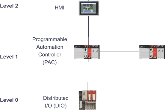
![]() Level 0: Process: Level 0 is the “things” level in manufacturing IoT and consists of sensors and actuators involved in the manufacturing process. These IoT devices perform IACS functions, such as moving a manufacturing robot, spraying, driving a motor, and welding. These devices are in communication with the basic control devices in Level 1.
Level 0: Process: Level 0 is the “things” level in manufacturing IoT and consists of sensors and actuators involved in the manufacturing process. These IoT devices perform IACS functions, such as moving a manufacturing robot, spraying, driving a motor, and welding. These devices are in communication with the basic control devices in Level 1.
![]() Level 1: Basic control: Level 1 is where the controllers that direct the manufacturing process live. These controllers interact with Level 0 IoT devices. In discrete manufacturing, a controller is usually a PLC, and in process manufacturing, it is known as a distributed control system (DCS).
Level 1: Basic control: Level 1 is where the controllers that direct the manufacturing process live. These controllers interact with Level 0 IoT devices. In discrete manufacturing, a controller is usually a PLC, and in process manufacturing, it is known as a distributed control system (DCS).
![]() Level 2: Area supervisory control: Level 2 includes functions within the cell/area zone that require runtime supervision and operation. Some examples include HMIs, alarms, and control workstations.
Level 2: Area supervisory control: Level 2 includes functions within the cell/area zone that require runtime supervision and operation. Some examples include HMIs, alarms, and control workstations.
Figure 9-4 illustrates the types of device and corresponding interfaces in Levels 0–2.
![]() Level 3: Site level: The applications and functions at Level 3 include SCADA systems, file servers, control room workstations, scheduling systems, and reporting systems. Note that this level is not a subset of the cell/area zone but is part of the larger manufacturing zone.
Level 3: Site level: The applications and functions at Level 3 include SCADA systems, file servers, control room workstations, scheduling systems, and reporting systems. Note that this level is not a subset of the cell/area zone but is part of the larger manufacturing zone.
![]() Demilitarized zone (DMZ): The DMZ is the CPwE demarcation between the plant operational network and the traditional network. DMZ security is critical to plant operations as it protects the machines at the lower level from malicious activity that may occur in the traditional enterprise network.
Demilitarized zone (DMZ): The DMZ is the CPwE demarcation between the plant operational network and the traditional network. DMZ security is critical to plant operations as it protects the machines at the lower level from malicious activity that may occur in the traditional enterprise network.
![]() Enterprise zone: Levels 4 and 5 in the enterprise zone relate to traditional IT/enterprise networking functions, including file services, Internet connectivity, and email systems.
Enterprise zone: Levels 4 and 5 in the enterprise zone relate to traditional IT/enterprise networking functions, including file services, Internet connectivity, and email systems.
The CPwE Reference Model
With the manufacturing industry’s acceptance of Ethernet for industrial applications, several new communications protocols have emerged that take advantage of both Ethernet and TCP/IP. In response to this trend, Cisco and Rockwell Automation began co-development of the Converged Plantwide Ethernet (CPwE) reference model, which is primarily focused on the transport of EtherNet/IP (discussed later in this chapter).
The CPwE solution is designed to enable the convergence of IACS applications with enterprise IT systems. Figure 9-5 illustrates the overall CPwE network architecture. In this framework, the cell/area zone contains the IACS devices from Levels 0 to 2. Devices that reside here, such as HMIs and controllers, belong to a single cell/area network. An HMI is simply the interface between the machine and the human operator. In the CPwE architecture, IACS devices communicate with EtherNet/IP and real-time control traffic throughout the cell/area using Ethernet. CPwE Ethernet networks come in various topologies, including redundant star, bus/star, and ring. A more detailed discussion of CPwE topologies and the redundancy technologies they utilize is provided later in this chapter.
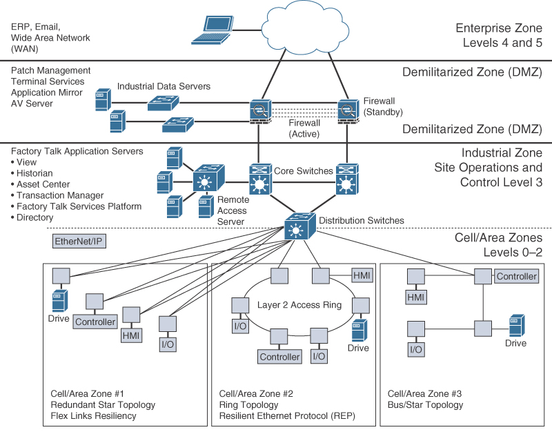
Figure 9-5 A High-Level View of the CPwE Architecture with Three Different Cell/Area Zone Ethernet Topologies
Ethernet infrastructure devices in the cell/area zone are predominantly industrial-grade access switches that are ruggedized and hardened against electrostatic discharge, are fanless, and support an extended temperature range. As shown in Figure 9-5, the distribution switches between the cell/area and industrial zones form a demarcation point. Because these distribution switches touch the same Ethernet segment as the access switches in the cell/area, they are also considered cell/area infrastructure devices and are typically required to be ruggedized devices. The distribution switch is also the demarcation point between Layer 2 and Layer 3.
The industrial zone is analogous to Level 3 of the IACS reference model and is also very similar to a traditional campus network. Most plants have only a single industrial zone. As with most campus networks, the industrial zone incorporates access switches for plant IT operations and employee services, and it includes core network functions. The industrial zone provides network connectivity through routed distribution switches to multiple cell/area zones as required. The industrial zone also supports IP routing capabilities for IACS devices that require Level 3 application support.
The demilitarized zone (DMZ) is the zone that sits between the industrial and enterprise zones and is used to securely manage traffic flows between networks in the adjacent zones. This is also the point where a plant firewall is typically implemented to control traffic flow into and out of the plant network.
CPwE Resilient Network Design
Due to sensitive controller and application requirements in IACS networks, network resiliency between IACS devices is a mandatory requirement within cell/area zones. Resilient IACS networks need to support the following capabilities:
![]() Availability: LAN topology design is critical in supporting IACS application uptime and business continuity. IACS applications have stringent requirements that must be considered for the LAN design, including network availability, performance, and distance between equipment. For critical operations where uptime is crucial, a fully redundant physical path in the IACS Ethernet network topology should be chosen.
Availability: LAN topology design is critical in supporting IACS application uptime and business continuity. IACS applications have stringent requirements that must be considered for the LAN design, including network availability, performance, and distance between equipment. For critical operations where uptime is crucial, a fully redundant physical path in the IACS Ethernet network topology should be chosen.
![]() Predictable performance: Meeting the predictable, reliable, and real-time traffic requirements of IACS applications is a requirement for successful CPwE deployments.
Predictable performance: Meeting the predictable, reliable, and real-time traffic requirements of IACS applications is a requirement for successful CPwE deployments.
![]() Fast network reconvergence: In the event of equipment or link failure, network restoration times need to be minimized so that other IACS devices are not impacted by the failure. Typical IACS application interruption tolerance limits are on the order of less than 100 ms, with minimal jitter.
Fast network reconvergence: In the event of equipment or link failure, network restoration times need to be minimized so that other IACS devices are not impacted by the failure. Typical IACS application interruption tolerance limits are on the order of less than 100 ms, with minimal jitter.
![]() Industrial protocol support: CPwE IACS devices and networking equipment need to support industrial application protocol requirements.
Industrial protocol support: CPwE IACS devices and networking equipment need to support industrial application protocol requirements.
The following are examples of communication patterns that require network resiliency:
![]() Controller to HMI
Controller to HMI
![]() Controller to controller
Controller to controller
![]() Controller to input/output (I/O; the sensor and controller modules for machines)
Controller to input/output (I/O; the sensor and controller modules for machines)
![]() Controller to variable frequent drives (VFDs; adjustable electromechanical drives to control a motor)
Controller to variable frequent drives (VFDs; adjustable electromechanical drives to control a motor)
![]() Controller to motor control centers (MCCs; used in factories to control a large number of motors from one central controller)
Controller to motor control centers (MCCs; used in factories to control a large number of motors from one central controller)
As illustrated in Figure 9-5, several different Ethernet topologies may be used in the cell/area zone, but in all cases, high availability of the Ethernet segment within the zone is a requirement. Depending on the Ethernet topology that is implemented, different high-availability technologies may be used to achieve application continuity. For example, in a simple redundant-star topology, network resiliency technologies such as Flex Links or cross-stack EtherChannel are popular. Flex Links have dual uplinks where one is active and one is standby. If the active link fails for some reason, the backup link takes over. With EtherChannel, both the uplinks are used simultaneously, and traffic is load balanced across the two links. If either of them fails, the other is still active, but with half the available uplink bandwidth.
Consider the example of how the CPwE model was used to improve the manufacturing system of one of the largest motorcycle manufacturers in the world. The company was building hundreds of motorcycles each shift, but it was dealing with significant manufacturing challenges due to the complexity of supporting different vehicle configurations. The company’s key objective was to improve agility in the manufacturing process. It was able to address this by bringing machine data into a central dashboard over the Ethernet network. This approach allowed the company to collate data from across the factory, allowing better response situations on the plant floor and, ultimately, a substantial reduction in machine downtime.
Having the ability to quickly bring new machines online and connect them to the Ethernet network has yielded much greater flexibility and has significantly reduced new model and new product introduction, thus improving the overall time to market.
Resilient Ethernet Protocol (REP)
In the CPwE reference architecture, Resilient Ethernet Protocol (REP) is used in the cell/area zone to achieve high-speed protection of ring topologies.
Similar to Spanning Tree Protocol (STP), standardized in IEEE 802.1D and its successors that support higher-speed convergence, REP controls a group of ports connected to an Ethernet segment to ensure that no bridging loops exist and that the Ethernet segment is able to respond to topology changes. When used on a fiber infrastructure, REP is able to achieve sub-50 ms convergence times when a link in a segment is broken or some other topology change occurs (such as a switch failure). Another key advantage of REP is that it is not limited to a small number of devices on a single Ethernet segment. Traditional STP is limited to only seven devices per segment, a number that can quickly become the limiting factor on the plant floor. Conversely, REP has no fixed upper limit on the number of nodes per segment, thus supporting large ring topologies.
For each REP segment, one switch is designated as a master node that controls the overall ring. The master node requires three critical pieces of information:
![]() Identification of the REP control VLAN, which allows the REP control messages to be communicated throughout the segment
Identification of the REP control VLAN, which allows the REP control messages to be communicated throughout the segment
![]() The location of the edges of the REP segment
The location of the edges of the REP segment
![]() The preferred place to break the ring under normal conditions, which is called the “alternate port” (If none is configured, REP automatically selects the alternate port, making the decision nondeterministic.)
The preferred place to break the ring under normal conditions, which is called the “alternate port” (If none is configured, REP automatically selects the alternate port, making the decision nondeterministic.)
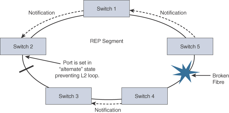
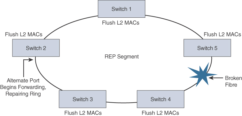
A REP segment is a chain of ports on an Ethernet segment configured with a segment ID. When all ports in the ring segment are active, one port is identified as the alternate port, meaning it is in the blocking state, thus preventing the ring from becoming a Layer 2 bridging loop. If any other port in the REP segment fails, the alternate port is signaled to change state into the forwarding state, repairing the broken Ethernet ring segment and allowing communications to continue.
REP uses a loss of signal (LOS) detection mechanism to learn of adjacent neighbor failures on the segment. When a switch port detects a REP segment failure (such as a fiber break or a physical switch failure), notification messages indicating a link failure are sent to all the other REP switches. In addition to notifying the alternate port to change to a forwarding state, these notification messages signal that the MAC addresses in content addressable memory (CAM) of all switches must be flushed. In this manner, a new bridging path is formed. Figures 9-6 and 9-7 illustrate the REP failure notification and repair mechanism.
Although there are many proprietary Ethernet Ring Protection Switching (ERPS) technologies available on the market today (including REP), there has also been an effort to standardize high-speed ERPS. This effort has been led by the ITU-T under G.8032. G.8032 has many similarities to REP, including sub-50 ms ring protection times and the support for a multitiered ladder topology. While the industry is now beginning to move toward G.8032 as the standard for high-speed ERPS, G.8032 still struggles with limited commercial availability.
As plant network convergence drives significant change in manufacturing organizations, systems, and networks, REP plays an important role in improving application availability. In the event of a network disruption, REP networks support continued IACS functionality and reduced downtime costs while preserving throughput productivity and sustained operations. Applications deployed in a REP environment support a wide variety of manufacturing disciplines, including batch, discrete, process, and hybrid manufacturing.
Business Value of Resiliency in Converged Networks
Designing a factory with network resiliency has a significantly positive business impact for a manufacturer. Increasing numbers of devices are being connected on the plant floor. These devices are being connected using the same network technology as the Internet. Devices, such as sensors, embedded into manufacturing devices that collect data are now used as tools to better understand complex processes. Today, when work on cell/area zone network devices requires significant planning and outage, a resilient network design allows a single device to be taken out of service without impacting the rest of the cell/area network. The network is thus more forgiving of single-point outages, allowing flexibility in network upgrades and maintenance.
REP-based architectures enhance the production network’s resilience and ability to support systems that connect people, processes, and data to real-time applications, even during a network disruption. In manufacturing, Ethernet networks are driving a new generation of connected, intelligent machines with improved network visibility into the plant.
CPwE Wireless
While CPwE is often deployed with wired Ethernet access switches, plantwide architectures are increasingly using Wi-Fi (IEEE 802.11) for critical IACS applications. These applications have similar network requirements to their wired Ethernet brethren in that they demand reliable data transfer and quality of service (QoS) handling with minimal latency and jitter for critical applications.
CPwE wireless networks can be used to manage machines, handheld devices, and automated guided vehicles (AGVs). Wireless brings the flexibility to quickly change a manufacturing line or move assets as needs arise, without worrying about the physical wiring. In addition, location-based tags and sensors are now being used to provide visibility to assets and goods moving around the plant floor.
CPwE Wireless Network Architecture
Wi-Fi networks differ significantly from traditional wired LANs in their use of shared radio frequencies, susceptibility to interference, and coverage impairments. Deploying a Wi-Fi network requires thoughtful planning and design, as well as periodic monitoring to meet expectations for bandwidth, QoS handling, throughput, reliability, and security. Most importantly, an industrial wireless local area network (WLAN) design and implementation must meet the performance requirements of IACS applications.
Wi-Fi is a wireless technology where stations need to “contend,” or compete, for their chance to send a frame over the air. This means that latency varies, depending on several factors, including how many stations are associated to the AP, how much traffic they are sending (including how busy the AP is), and interference. This could pose a serious problem for certain IACS applications that are latency sensitive. In cases where a control system needs predictable latency, alternate wireless technologies that use Time-Sensitive Networking (TSN), such as WirelessHART or ISA100.11a, are preferable over Wi-Fi. (These technologies are discussed in Chapter 4, “Connecting Smart Objects.”) The downside of these technologies is that they support much smaller bandwidth than Wi-Fi.
If Wi-Fi is chosen for the plant floor, the WLAN systems needs to be tailored to IACS use cases for Wi-Fi networking within the plant. The WLAN should integrate the IACS into the broader manufacturing environment, and a wide range of client device types and applications should be taken into consideration, along with the strictness of the latency required by the IACS application.
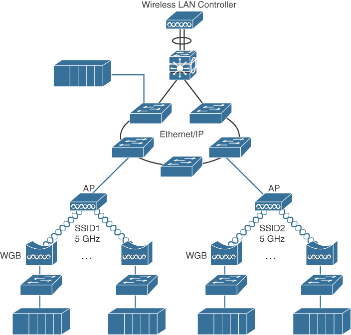
One such architecture that uses a centralized wireless LAN controller (WLC) to manage the APs distributed throughout the plant is illustrated in Figure 9-8. By using a WLC, a centralized management model is created, thus introducing security and self-healing mechanisms to the wireless network.
Note
While the focus in this chapter is on centralized controller-based WLANs, the CPwE design and implementation guides provide details of autonomous AP deployment models in the connected factory. While controller-based Wi-Fi deployments are becoming very popular, you are likely to see many factories still using autonomous APs that do not use a controller.
The following are several use-case examples where Wi-Fi is used in manufacturing environments:
![]() Fixed-position devices: Fixed-position devices in the WLAN have a permanent operational location and are also known as “static.” Fixed-position wireless is an alternative to a wired connection for hard-to-reach and remote locations where cabling is too expensive or impossible to install. Usage areas include process control, machine condition monitoring, fixed environmental monitoring, and energy industries. In the manufacturing environment, a common use case is a standalone original equipment manufacturer (OEM) machine or skid that needs to be integrated into a production line over a wireless link.
Fixed-position devices: Fixed-position devices in the WLAN have a permanent operational location and are also known as “static.” Fixed-position wireless is an alternative to a wired connection for hard-to-reach and remote locations where cabling is too expensive or impossible to install. Usage areas include process control, machine condition monitoring, fixed environmental monitoring, and energy industries. In the manufacturing environment, a common use case is a standalone original equipment manufacturer (OEM) machine or skid that needs to be integrated into a production line over a wireless link.
![]() Nomadic devices: Nomadic equipment stays in place while operating and then moves to a new location in the shutdown state. After relocation, a new wireless connection commonly needs to be established. Examples are process skids, storage tanks, reactors, and portable manufacturing equipment.
Nomadic devices: Nomadic equipment stays in place while operating and then moves to a new location in the shutdown state. After relocation, a new wireless connection commonly needs to be established. Examples are process skids, storage tanks, reactors, and portable manufacturing equipment.
![]() Operational relocation devices: Some mobile equipment changes position during an operation, while remaining in the same wireless coverage zone. Examples include rotary platforms and turntables, automated storage and retrieval systems (ASRS), assembly systems, overhead cranes, and similar machinery that uses wireless as a replacement for wired solutions, such as inductive rails and slip rings. These applications may require rapid changes in position and orientation of the wireless client relative to the AP within the coverage area.
Operational relocation devices: Some mobile equipment changes position during an operation, while remaining in the same wireless coverage zone. Examples include rotary platforms and turntables, automated storage and retrieval systems (ASRS), assembly systems, overhead cranes, and similar machinery that uses wireless as a replacement for wired solutions, such as inductive rails and slip rings. These applications may require rapid changes in position and orientation of the wireless client relative to the AP within the coverage area.
Deploying a factory Wi-Fi network based on centralized controller design principles allows you to overcome many common challenges, including shared radio frequencies, interference, and coverage impairments. The wireless LAN controller model also allows you to easily deploy key technology features, such as QoS, Wi-Fi security capabilities, and location services.
Real-Time Location System (RTLS)
When a factory Wi-Fi network is fully in place and offers thorough coverage of the plant floor, it may also be leveraged as an RTLS. RTLS solves a common problem in factories: the need to manage the location and status of plant materials.
Wi-Fi–based location tracking systems typically include active battery-powered Wi-Fi radio frequency identification (RFID) tags that are attached to machines, skids, vehicles, or other devices that have a measure of mobility within the plant.
Note
There are various Wi-Fi–based location tracking systems available on the market, and the accuracy of these technologies varies considerably. For example, RSSI/distance-based location techniques require data from several access points to calculate a device’s location. RSSI stands for received signal strength indicator and is simply a measurement of the power in an incoming radio wave. In contrast, Wi-Fi–based angulation (also known as angle of arrival) techniques use an array of antennas on a single AP to measure the angle of arrival, and can typically produce much more accurate location estimates than the RSSI/ distance measurement approach. Many RFID tags use a small battery and send a message at a configurable interval (which can range from a few seconds to every hour), thus changing the accuracy in the time dimension. Larger devices may include a bigger battery, allowing for a signal to be sent each second or more often. For this reason, RTLS is often referred to as nRTLS, or Near Real-Time Location System.
By using RTLS and a graphical location visualization tool, it is possible for assembly workers, shift supervisors, and plant managers to view the location of plant materials and assets through tablets and smart phones. With real-time visibility into track production, floor managers are also able to track each line’s output and determine whether production is meeting daily targets.
A good example of RTLS in practice comes from one of the world’s leading airplane manufacturers. This manufacturer decided to equip all the safety equipment on its planes with RFID tags. When an aircraft goes through maintenance, one job is to inspect each piece of equipment and verify that it is accounted for. Without RFID tags, this job took on average 6.5 hours per plane. With RFID tags in place, the time dropped to 20 minutes per plane. On the factory floor, using RFID tags to locate airplane parts has allowed the company to assemble planes faster by using movement optimization software that moves parts where they are needed and removes objects that may reduce access to other parts. The company estimate its gain per year per factory at $100 million.
Using RTLS also allows plant managers to monitor how quickly employees are completing their respective stages in the production process. The business value of RTLS in manufacturing is that it helps factory managers better understand how to increase efficiency and lower costs associated with inventory. By tracking inventory and the location of materials, RTLS is also able to help improve customer service by providing accurate delivery schedules.
Industrial Automation Control Protocols
Industrial automation application systems use a unique set of protocols for control, motion, synchronization, and safety. The development of these industrial protocols began long before the days of Ethernet and IP, but in recent years, efforts have been made to adapt these automation protocols to take advantage of the benefits of modern transport mechanisms.
The list of available automation control protocols is very long, but the three with the largest market adoption are discussed in the following sections: EtherNet/IP, PROFINET, and Modbus/TCP.
EtherNet/IP and CIP
EtherNet/IP is an open standard for industrial automation systems that was developed by Rockwell Automation and is now managed by the Open DeviceNet Vendors Association (ODVA). Note that in the case of EtherNet/IP, “IP” stands for “Industrial Protocol,” not “Internet Protocol.” Industrial Protocols are specifically used to handle industrial automation applications, such as those for control, safety, motion, and configuration.
EtherNet/IP adapts the Common Industrial Protocol (CIP) to standard Ethernet and TCP/IP technology. CIP is a communications protocol used for I/O control, device configuration, and data collection in automation and control systems. CIP includes capabilities for the following types of communications:
![]() Implicit messaging: This type of messaging involves real-time I/O data, functional safety data, motion control data, and often UDP multicast.
Implicit messaging: This type of messaging involves real-time I/O data, functional safety data, motion control data, and often UDP multicast.
![]() Explicit messaging: This type of messaging involves configuration, diagnostics, and data collection, and it is based on TCP unicast messaging.
Explicit messaging: This type of messaging involves configuration, diagnostics, and data collection, and it is based on TCP unicast messaging.
Figure 9-9 illustrates a manufacturing network based on EtherNet/IP. As discussed in the previous section, REP is used as a resiliency mechanism between the industrial Ethernet switches (IESs) to pass CIP Class 1 (real-time Ethernet) and Class 3 (TCP) messages.
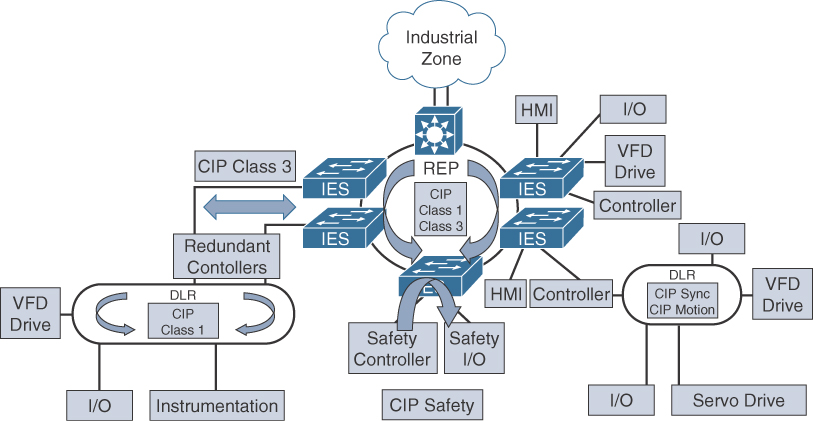
EtherNet/IP also specifies a redundancy protocol known as Device Level Ring (DLR), which is used when the system requires continuous operation and is able to achieve high-speed reconvergence in the case of a ring break. DLR is optimally deployed where devices have an integrated two-port switch and do not require separate industrial Ethernet switches.
Note
The CPwE reference architecture for industrial applications discussed earlier is largely based on EtherNet/IP and CIP.
PROFINET
PROFINET (Process Field Net) is a widely used industrial technology for the exchange of data between controllers and devices. One of the key advantages of PROFINET is that it exchanges messages in a deterministic manner over high-speed Ethernet links. Unlike Modbus TCP, which uses TCP to communicate between devices (thus requiring devices to establish and maintain a TCP socket connection), or EtherNet/IP, which uses UDP, PROFINET is able to send and receive data directly to the application layer, without having to wait for processing in the TCP/IP stack, which has the potential of introducing variable delay.
How does PROFINET compare with EtherNet/IP? EtherNet/IP and PROFINET are different standards for industrial automation and are the two leaders in the industrial Ethernet fieldbus market. In a nutshell, EtherNet/IP is supported by ODVA and was developed by Rockwell Automation, which is a leader in the manufacturing industry, especially in North America. PROFINET is supported by PROFINET International (PI) and is the market leader in Europe and the Middle East; it is supported by Siemens and other vendors.
From a networking perspective, a key difference is in how the two standards approach deterministic networking and real-time communications. EtherNet/IP leverages UDP/IP for real-time communications (similar to Voice over IP applications), whereas PROFINET uses a unique EtherType to bypass the UDP/IP layers of the stack to allow direct application communication.
PROFINET is fully compatible with standard IEEE 802.3 Ethernet, which means regular Ethernet devices can coexist with PROFINET I/O devices and controllers on the same segment. However, PROFINET also has some significant differences from standard Ethernet. For example, PROFINET is a deterministic protocol, which means frames are sent and received at specific times. This is especially important in discrete manufacturing, when a controller needs to send a message to a device to stop or change operation.
PROFINET applications are time sensitive. Network services, applications, and devices are all dependent on command and control traffic being delivered within strict delay tolerances, which means any network-induced delay is a critical design consideration. To address this, PROFINET networks are designed to support real-time PROFINET communications with minimal latency, while supporting network resiliency at the manufacturing plant floor. PROFINET architectures consist of the following:
![]() Industrial automation devices: These include robots, sensors, actuators, and drives.
Industrial automation devices: These include robots, sensors, actuators, and drives.
![]() HMIs: HMIs provide visual status reports and control of the industrial automation devices.
HMIs: HMIs provide visual status reports and control of the industrial automation devices.
![]() Controllers: Examples include PLCs and distributed I/O devices.
Controllers: Examples include PLCs and distributed I/O devices.
A well-designed PROFINET architecture provides the following operational benefits:
![]() It reduces the risk of production downtime through the use of a resilient network architecture capable of network convergence based on the IEC 62439-2 standard. IEC 62439-2 is covered in more detail later in this chapter, in the section “Media Redundancy Protocol (MRP).”
It reduces the risk of production downtime through the use of a resilient network architecture capable of network convergence based on the IEC 62439-2 standard. IEC 62439-2 is covered in more detail later in this chapter, in the section “Media Redundancy Protocol (MRP).”
![]() It improves plant uptime through validated reference architectures, with a focus on application availability.
It improves plant uptime through validated reference architectures, with a focus on application availability.
![]() It enriches critical information access from machines and applications through better managed network resources.
It enriches critical information access from machines and applications through better managed network resources.
![]() It enhances single-pane management compliance, using industry standard general system description (GSD) files and supervisor applications of PROFINET-compliant devices. GSD files contain a device’s capabilities and characteristics, and they enable efficient integration, configuration, and management of that device in a PROFINET network.
It enhances single-pane management compliance, using industry standard general system description (GSD) files and supervisor applications of PROFINET-compliant devices. GSD files contain a device’s capabilities and characteristics, and they enable efficient integration, configuration, and management of that device in a PROFINET network.
The PROFINET Architecture
The PROFINET architecture for the connected factory is similar in many ways to the CPwE architecture discussed previously, including support for network resiliency services provided to devices, equipment, and applications in an industrial automation environment.
Similar to CPwE, PROFINET leverages the Purdue Model for Control Hierarchy. The cell/area zone (Levels 0–2) is where most of the real-time PROFINET traffic moves between industrial automation system devices. The upper manufacturing zone acts as an aggregation point for one or more cell/area zones.
The PROFINET architecture utilizes strict traffic segregation methods to protect industrial automation applications from external and internal interruptions. Disruptions in the control network—even short ones lasting just milliseconds—can create significant impacts on the functioning of a production facility.
Network resiliency is the primary consideration in the PROFINET architecture shown in Figure 9-10.
Much as with CPwE, the cell/area zone is the primary zone where most of the industrial automation activities are performed. It is important to consider this zone as an isolated entity of the manufacturing environment where availability and performance are the most important considerations.
Media Redundancy Protocol (MRP)
Determinism and network performance are key requirements for PROFINET stability in the cell/area zone. Determinism in industrial automation ensures that Ethernet frames are sent and arrive when required. While the PROFINET device is responsible for scheduling and transmitting the Ethernet frame, the network’s main impact on a system’s determinism is based on the following performance characteristics:
![]() Latency: The average amount of time a message takes to be transmitted and processed from originating node to destination node
Latency: The average amount of time a message takes to be transmitted and processed from originating node to destination node
![]() Jitter: The amount of variance in the latency
Jitter: The amount of variance in the latency
![]() Packet Loss: The number of packets, usually expressed as a percentage, lost in a transmission from one device to another
Packet Loss: The number of packets, usually expressed as a percentage, lost in a transmission from one device to another
Industrial automation networks need to have low levels of latency and jitter, and they need to support reliable data transmission for real-time applications. In industrial automation implementations, an application’s timing requirements often vary, depending on the underlying process, system, or devices.
Industrial automation networks must adhere to the following requirements for real-time applications:
![]() Machine and process cycle times: This includes the frequency with which the industrial automation application moves from one operation to the next.
Machine and process cycle times: This includes the frequency with which the industrial automation application moves from one operation to the next.
![]() Request packet interval (RPI) or I/O update time: This is the frequency at which input and outputs are sent and received.
Request packet interval (RPI) or I/O update time: This is the frequency at which input and outputs are sent and received.
![]() Packet-loss tolerance: This is the number of consecutive packet intervals lost before an application generates errors or fails into a safe state.
Packet-loss tolerance: This is the number of consecutive packet intervals lost before an application generates errors or fails into a safe state.
To meet these strict requirements and protect against application layer issues of link or switch failure, PROFINET supports a ring resiliency protocol known as Media Redundancy Protocol (MRP). MRP is an industry protocol defined in the IEC 62439-2 standard. MRP allows rings of industrial Ethernet switches to overcome a single segment failure with recovery times similar to those of REP. MRP is suitable for industrial Ethernet applications and is natively supported in PROFINET.
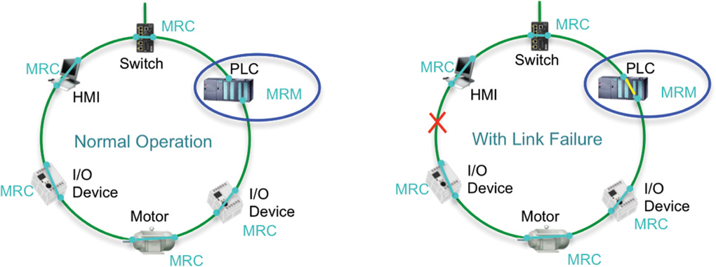
PROFINET-compliant industrial Ethernet switches support two roles in an MRP ring. In a ring topology, only one switch or industrial automation device can act as a media redundancy manager (MRM), and all other devices act as media redundancy clients (MRCs). The purpose of the MRM is to keep the ring loop free and provide redundancy when failure happens. The MRM does this by sending control packets or test frames from one ring port and receiving them on its other ring port. During normal operation, the control packets are received, and the MRM keeps a port blocked to prevent a loop. If the MRM does not receive its own control packet, this means the loop is not intact, and a network failure has occurred. The MRM informs the MRCs about the network failure. It unblocks its port and starts forwarding to provide connectivity until the network failure is resolved (refer to Figure 9-10).
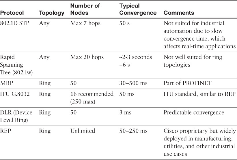
Table 9-1 provides a list of resiliency protocols and their interoperability with types of topology and convergence requirements.
Modbus/TCP
Modbus was originally introduced in the 1970s by Modicon (now Schneider). It is a serial communications protocol that is widely used in manufacturing, utilities, and many other industries. In the manufacturing world, Modbus is most commonly used for management of PLCs in a master/slave configuration. Much like other automation control standards, Modbus has been adapted to modern communications standards, including Ethernet and TCP/IP.
Modbus is popular due to the fact that the protocol is an open published standard and is well established throughout the world. The Modbus master/slave configuration is well suited to the connection-oriented nature of TCP, but this mode of communication tends to introduce extra latency and is generally not as flexible as either EtherNet/IP or PROFINET.
Modbus/TCP is discussed in greater detail in Chapter 6, “Application Protocols for IoT.”
Connected Factory Security
Manufacturing has become one of the top industries targeted by cyber criminals. Often, the solution has been simply to air-gap the factory floor network by disconnecting it from the IT enterprise network. However, a network disconnected from higher-layer functions is limited in its capabilities and business improvements that may be achieved through IoT. In addition, many threats arise from the plant floor computers and workstations that are physically accessible by contractors or employees with unfettered access. For example, consider the Stuxnet worm, mentioned in Chapter 2, “IoT Network Architecture and Design,” and Chapter 8, which is thought to have been introduced through a physical USB device on the internal network.
A Holistic Approach to Industrial Security
No single product, technology, or methodology can fully secure industrial applications from cyber attack. Protecting IACS assets requires a “defense-in-depth” security approach that addresses internal and external threats. This approach implements multiple layers of defense (physical, procedural, and electronic) at each IACS level.
A comprehensive IACS security framework should serve as a natural extension to the industrial control system network. However, for existing IACS deployments that have little in the way of security, the same defense-in-depth model can be applied incrementally to help improve the security posture of the IACS.
In most cases, holistic factory security requires that different stakeholders work together, including control system engineers, IT network engineers, and the IT security architects. Responsibilities for these different stakeholders include the following:
![]() Control system engineers:
Control system engineers:
![]() IACS device hardening (that is, physical and electronic)
IACS device hardening (that is, physical and electronic)
![]() Infrastructure device hardening (for example, port security)
Infrastructure device hardening (for example, port security)
![]() Network segmentation
Network segmentation
![]() IACS application authentication, authorization, and accounting (for example, AAA)
IACS application authentication, authorization, and accounting (for example, AAA)
![]() Control system engineers in collaboration with IT network engineers:
Control system engineers in collaboration with IT network engineers:
![]() Zone-based policy firewalls at the IACS application
Zone-based policy firewalls at the IACS application
![]() Operating system hardening
Operating system hardening
![]() Network device hardening (for example, access control, resiliency)
Network device hardening (for example, access control, resiliency)
![]() Wireless LAN access control policies
Wireless LAN access control policies
![]() IT security architects in collaboration with control systems engineers:
IT security architects in collaboration with control systems engineers:
![]() Identity services (wired and wireless)
Identity services (wired and wireless)
![]() Remote access servers
Remote access servers
![]() Plant firewalls
Plant firewalls
![]() Industrial demilitarized zone (IDMZ) design best practices
Industrial demilitarized zone (IDMZ) design best practices
Figure 9-11 illustrates an overall holistic security architecture for the connected factory and highlights places where each of these security considerations need to be implemented.
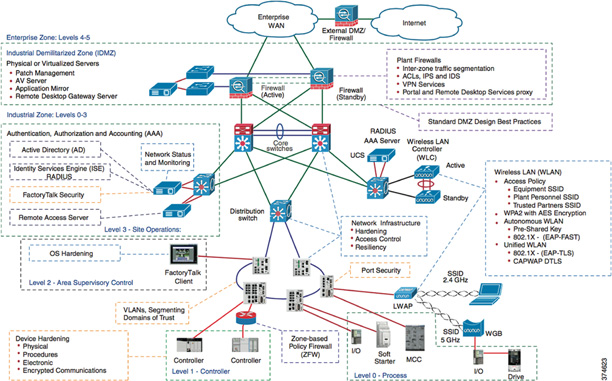
While industrial network security is a vast subject, it can be treated only briefly in this book. The following sections address three aspects of factory security:
![]() Network Address Translation in the factory
Network Address Translation in the factory
![]() The industrial DMZ
The industrial DMZ
![]() Factory security identity services
Factory security identity services
Network Address Translation in the Factory
Whether you are an end user, an OEM, or a system integrator, IP addresses in your IACS application may need to be reused. Network Address Translation (NAT) enables the reuse of IP addressing without introducing duplicate IP address errors into your IACS application architecture.
Technology and business aspects drive the decision to use NAT:
![]() Business drivers: Machine builder OEMs often produce similar machines that all have the same IP address and rely on NAT to enable the rapid deployment and replication of skids and machines, including IP addressing. This helps reduce development and commissioning costs.
Business drivers: Machine builder OEMs often produce similar machines that all have the same IP address and rely on NAT to enable the rapid deployment and replication of skids and machines, including IP addressing. This helps reduce development and commissioning costs.
![]() Technology drivers: NAT is used when the IP address space in the plantwide network infrastructure is limited and not every device needs to communicate outside the skid or machine-level network.
Technology drivers: NAT is used when the IP address space in the plantwide network infrastructure is limited and not every device needs to communicate outside the skid or machine-level network.
Plantwide architectures require unique IP addressing for each device. NAT is a networking technology that enables control system engineers to build IACS applications that reuse IP addresses, while allowing those IACS applications to integrate into the larger plantwide architecture.
NAT can be configured to translate specific IP addresses from inside the IACS application to the outside plant network. Doing so provides the added benefit of effectively hiding the inside IP addressing scheme of the IACS application. NAT translations have two forms: one-to-one (1:1) and one-to-many (1:n).
It is important to note that the NAT design needs to be scalable because multiple cells/areas may be present in a factory network.
A common use case, as depicted in Figure 9-12, is the coordination of control functions of an OEM machine by a line controller. In this case, there are multiple machines, each with its own machine controller. Note, however, that there is one line controller on the outside, used for both machines. Both IACS devices have been deployed with the same IP address and require NAT to communicate with the line controller.
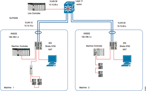
VLAN 10 is deployed for Machine 1, VLAN 20 for Machine 2, and VLAN 30 for the line controller. Machine 1’s NAT switch translates the inside IP address (192.168.1.x) of the machine controller to an outside IP address (10.10.10.x) on VLAN 10. The NAT switch also translates the outside IP address of the default gateway (the Layer 3 switch) to an inside IP address. Correspondingly, Machine 2’s NAT switch translates the inside IP address (192.168.1.x) of the machine controller to an outside IP address (10.10.20.x) on VLAN 20. Likewise, Machine 2’s NAT switch also translates the outside IP address of the default gateway to an inside IP address.
Between the Layer 3 switch and the NAT switches is a unique VLAN for each machine, and each controller has a unique outside IP address. The Layer 3 switch on the outside routes the outside IP address of each machine controller either to the line controller (vertical interlocking) on VLAN 30 or to the other machine VLAN (horizontal interlocking).
This scalable use case enables the integration of multiple skids or machines with a duplicated IP addressing scheme into the same line controller VLAN. For this use case, a NAT-capable industrial Ethernet switch is required for each skid or machine. A Layer 3 distribution-layer switch is also required to enable routing between the VLANs.
The Industrial DMZ
IACS networks run a manufacturing business. Although several attack vectors into IACS systems exist, penetration from the enterprise zone continues to be a key focus of the security architecture. To deal with this threat, many organizations and standards bodies recommend segmenting the business system networks from the plant networks by deploying an industrial demilitarized zone (IDMZ).
The IDMZ is a buffer that enforces data security policies between a trusted network (industrial zone) and an untrusted network (enterprise zone). The demilitarized zone concept is commonplace in traditional IT networks but is still in early adoption for IACS applications.
The IDMZ exists as a separate network located at a level between the industrial (identified as the manufacturing zone in the Purdue model in Figure 9-3) and enterprise zones, commonly referred to as Level 3.5. An IDMZ environment consists of numerous infrastructure devices, including firewalls, VPN servers, IACS application mirrors, and reverse proxy servers, in addition to network switches, routers, and virtualized services.
For secure IACS data sharing, the IDMZ contains assets that act as brokers between zones. Multiple methods to broker IACS data across the IDMZ exist:
![]() A reverse proxy server
A reverse proxy server
![]() An application mirror, which is similar to a proxy server—essentially a facsimile of the actual application running outside the protected data center
An application mirror, which is similar to a proxy server—essentially a facsimile of the actual application running outside the protected data center
![]() Remote desktop services (such as Microsoft RDP)
Remote desktop services (such as Microsoft RDP)
Key IDMZ design principles include the following:
![]() All IACS network traffic from either side of the IDMZ terminates in the IDMZ; no IACS traffic directly traverses the IDMZ, leaving no direct path between the industrial and enterprise zones.
All IACS network traffic from either side of the IDMZ terminates in the IDMZ; no IACS traffic directly traverses the IDMZ, leaving no direct path between the industrial and enterprise zones.
![]() Industrial control traffic does not enter the IDMZ; it remains within the industrial zone.
Industrial control traffic does not enter the IDMZ; it remains within the industrial zone.
![]() Primary services are not permanently stored in the IDMZ.
Primary services are not permanently stored in the IDMZ.
![]() All data is transient, meaning the IDMZ does not permanently store data.
All data is transient, meaning the IDMZ does not permanently store data.
![]() Functional subzones are used within the IDMZ to segment access to IACS data and network services (for example, partner access to resources).
Functional subzones are used within the IDMZ to segment access to IACS data and network services (for example, partner access to resources).
![]() A properly designed IDMZ also supports the capability of being unplugged if compromised, while still allowing the industrial zone to operate without disruption.
A properly designed IDMZ also supports the capability of being unplugged if compromised, while still allowing the industrial zone to operate without disruption.
Factory Security Identity Services
As access methods to the industrial network expand, the complexity of managing network access security and controlling unknown risks continues to increase. With a growing demand for in-plant access by contractors (such as OEMs and system integrators), plantwide networks face continued security threats.
In addition, IACS networks need to be secured against untrusted (and potentially compromised) computers, such as those used by contractors or partner vendors. With the proliferation of contractor devices in manufacturing plants and constrained plantwide operational resources, the potential impact of failing to identify and remediate security threats introduces a significant risk to plantwide operations.
Network identity services provide an additional layer of network access and control by identifying the type of computer, operating system, and user that is accessing the network. Based on the identity and applying a corresponding policy, identity services are able to push security policies to the network infrastructure that the computer is accessing. Since identity services are typically tied to directory services (such as LDAP or Microsoft Active Directory), the common practice is to use a centrally managed identity services model, with the IT department maintaining management of the identity system that operates from the industrial zone.
It is important to note that the security architecture likely needs to support both wired and wireless access methods by plant personnel and contractors. This is achieved by deploying a centralized identity services system that is capable of establishing a trust boundary on all network access points.
This approach provides the following benefits:
![]() A comprehensive centralized policy for network access in both the manufacturing and enterprise zones
A comprehensive centralized policy for network access in both the manufacturing and enterprise zones
![]() Streamlined device onboarding
Streamlined device onboarding
![]() Policy-driven rules and access control policies
Policy-driven rules and access control policies
![]() Guest portal services for contractors and guests
Guest portal services for contractors and guests
Through the incorporation of a centralized identity system, policies can be applied across the network in real time so users experience consistent access to their services from both wired and wireless connections. In addition, unknown devices are directed to an administratively defined safe destination with no access to local resources in the plantwide operations, whereas trusted devices are granted access to essential platforms in the industrial zone.
Identity service tools also enable centralized guest portal services as well as policies for self-service registration of plant personnel, vendors, partners, and guests.
Edge Computing in the Connected Factory
Machines on the plant floor are capable of producing a massive amount of data. One way many factories have dealt with this challenge is to deploy PCs to collect this data. Collecting data from PCs on the plant floor has led to maintenance and security challenges, since each PC requires patching and operating system upgrades. Hardware failures are also common because the devices are often not ruggedized for factory conditions. Clearly, this approach makes it very difficult for factory operations to aggregate, digest, and respond to the data effectively. Such an approach is a major impediment to the visibility and the latent business benefits that could result from factory data analytics.
New trends in compute capacity at the network edge are helping resolve these dilemmas. With machine-embedded and near-machine edge compute devices that include switching, routing, and security features in a single ruggedized form factor, manufacturers are beginning to realize the value of connecting machines and edge compute services.
Connected Machines and Edge Computing
Connecting machines to plant-level applications requires a communications model and data scheme that is extensible, secure, and easy to implement. Several open manufacturing communications protocols have been developed that provide interoperability between devices and software, allowing you to monitor and then harvest data from the production floor. These protocols are generally based on XML or HTTP.
Different data standards exist for different machine types, so you should expect some heterogeneity in data protocols on the plant floor. For example, MTConnect is common for computer numerical control (CNC) machines, OPC UA is widely used in industrial automation, and PackML is used in packaging machines.
New developments in edge computing platforms combine switching, NAT, routing, and security features into a single ruggedized edge appliance. This edge services approach reduces costs for secure machine data collection and optimizes available network resources and bandwidth by analyzing data on the plant floor prior to transmitting it to the data center or cloud for further analysis.
The edge appliance typically includes a basic open source and efficient operating system like Linux, which runs a streaming analytics application and the required standard data agents needed for the respective machine types.
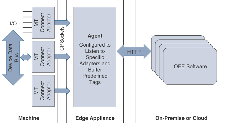
Hardware adapters for standard protocols are installed on the machine that define I/O tags for each machine and broadcast change of state for each tag to the agent on the edge appliance. The agent that resides on the edge appliance is configured to listen to specific adapters and buffer the predefined tags. Edge streaming analytics can be configured to parse the data and determine what is useful for further consideration and analysis. The refined data is then sent over HTTP or XML to an on-premises or cloud-based data center running a big data consumption and processing engine, such as Hadoop.
OEE analytics tools can be used for data visualization. (OEE is defined earlier in this chapter, in the section “An Introduction to Connected Manufacturing.”) In some cases, OEM machine builders produce custom analytics software that can be delivered on-premises or through the cloud. Figure 9-13 illustrates the machine hardware adapter being used to pass data to an agent on the edge node/edge appliance for analysis and then only refined data being sent to the cloud for further analysis.
Because the data can be sourced from disparate resources, it may be preferable to manage the applications in an enterprise portal environment with identity management capabilities. As machine builders mature in their delivery of OEE analytics for preventive maintenance, it is anticipated that they will increasingly deliver web services using RESTful APIs that can be consumed in a connected machine’s web portal for end-user manufacturers. Modern portal applications allow these services to be consumed from disparate sources with secure identity and Single Sign-On (SSO) capabilities.
For large manufacturers with heterogeneous plant floors, the task of identifying data standards for each machine type and working with machine builders to architect a solution can be daunting. Meanwhile, when enabled by a resilient, secure, and converged connected factory infrastructure with industrial Ethernet edge switches, the benefits of edge computing and storage can be realized in a reasonable timeframe. Figure 9-14 shows an example of how edge computing can be deployed on a ruggedized industrial switch directly attached to machines in the manufacturing zone.
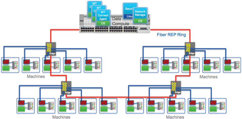
An excellent example of connected factory edge computing is in one of the world’s leading industrial robot companies. This robot company uses edge computing and big data analytics to identify maintenance procedures that can prevent breakdowns before they occur. With the company’s zero downtime (ZDT) solution, the robot is connected through an edge computing appliance running the ZDT agent through the plant network. The data relevant for optimizing maintenance is securely transmitted to a hosted cloud environment, where the analytics software captures out-of-range exceptions and predicts needed maintenance. When a maintenance period is identified, an alert is sent from the cloud application to service personnel, alerting them to the need for service. The required parts are then shipped to the factory in time for the next scheduled maintenance window. With thousands of robots connected through the ZDT application for one major auto manufacturer, this has helped save millions of dollars in unplanned downtime.
Summary
The world of manufacturing is rapidly moving toward digital transformation. Manufacturers are migrating disparate independent systems toward converged networks and control protocols. The ISA99 Committee for Manufacturing and Control has outlined an architectural model known as IACS model that is built on the Purdue Model for Control Hierarchy (ISA99/IEC-62443), in which a series of zones and levels identify protocol sets, security boundaries, and operational models for the manufacturing plant. Converged Plantwide Ethernet (CPwE), championed by Cisco and Rockwell, builds on this model and defines a set of guidelines for IACS wired and wireless network design.
Fundamental to converged factory architectures are cell/area zone Ethernet resiliency protocols, such as REP, DLR, and MRP, which allow rapid Ethernet ring convergence. To support automation control requirements, specific control protocols have been developed for manufacturing that utilize standard communications protocols. Three of the most popular control protocols are EtherNet/IP, PROFINET, and Modbus/TCP.
When machines and other devices are connected to the cell/area zone within a factory, their security is paramount. To address this, private addresses are often used, thus requiring NAT services within the cell/area zone. In addition, centralized access control and device/user profiling through an identity service tool is highly recommended to ensure that untrusted computers and devices are not used within the industrial zone on networks.
Finally, manufacturers are beginning to benefit from edge computing within the cell/area zone. Manufacturing-specific edge applications are now being deployed that process machine data at the machine and send only relevant data to the cloud or data center.
References
1. SCM World/Cisco, Smart Manufacturing and the Internet of Things 2015 Survey of 418 Manufacturing Business Line and Executives and Plant Managers Across 17 Vertical Industries.
2. IHS 2014 Machines Report for Cisco.
3. PWC Internet of Things in Manufacturing 2015.
4. McKinsey Disruptive Technologies 2013 Report.