
To address further common design issues relating to service inventory architecture, this chapter provides a set of specialized patterns that help solve implementation-level problems.
Each of these five patterns targets a specific area of inventory architecture:
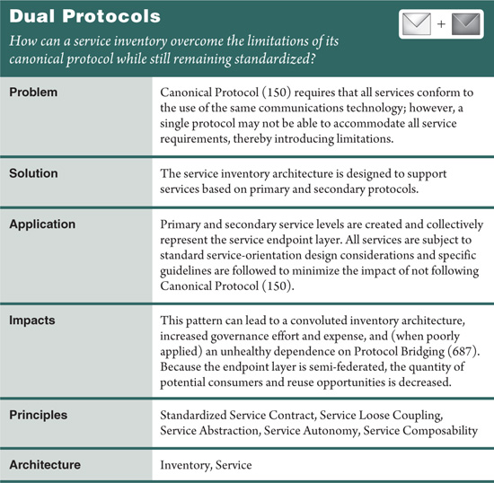
• Dual Protocols (227) provides a flexible solution that addresses the challenges of establishing a canonical communications protocol.
• Standardization of underlying technologies is advocated by Canonical Resources (237).
• State Repository (242) and Stateful Services (248) provide alternative solutions for runtime state data deferral.
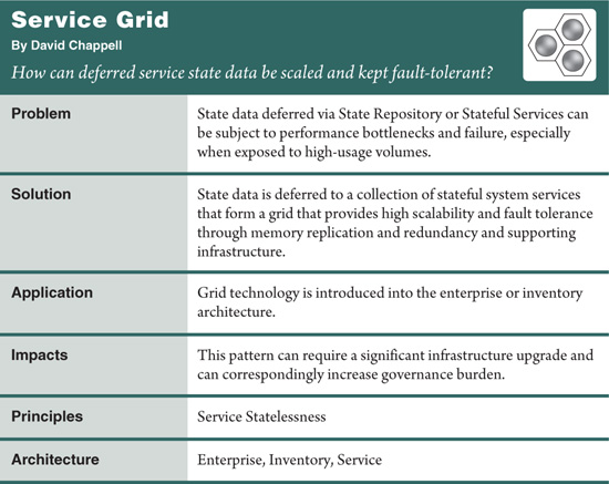
• Service Grid (254) proposes a sophisticated solution for state deferral and fault tolerance.
The following additional two patterns are focused on solving extra-inventory architectural concerns for environments in which multiple domain inventories exist or for when communication external to the inventory boundary needs to be accommodated:
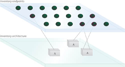
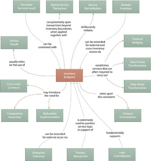
• Inventory Endpoint (260) establishes somewhat of a specialized proxy service that interacts with external consumers on behalf of services within the inventory boundary.
• Cross-Domain Utility Layer (267) proposes a design solution that changes the face of domain inventories by stretching a common layer of utility services across inventory boundaries.
Whereas the objective of Inventory Endpoint (260) is to preserve the integrity of services within a boundary at the cost of increasing logic redundancy, the goals behind Cross-Domain Utility Layer (267) are to open up portions of these boundaries for the purpose of reducing enterprise-wide redundancy and increasing reuse.
Note
Some of the patterns in this chapter reference the term “service activity.” Be sure to revisit the definition in Chapter 3 if the term is not familiar to you.
Note
For a definition of what the term “protocol” refers to in this pattern, see the What Do We Mean by “Protocol?” section in the pattern description for Canonical Protocol (150).
As advocated by Canonical Protocol (150), it is preferred for all services within an inventory to interact using the same communications technology. However, when inventory-wide protocol standardization is not possible or when the chosen communications technology is inadequate for certain types of data exchanges, it can compromise service interoperability, thereby undermining the overall goals of Canonical Protocol (150).
Two levels of services are delivered within the same inventory:
• a primary level based on the preferred protocol
• a secondary level based on an alternative protocol
This allows the secondary protocol to be used whenever the primary protocol is deemed deficient or inappropriate. This solution furthermore allows services based on the secondary protocol to be promoted to the primary protocol when appropriate.
A popular example of a transport plus messaging protocol combination that is chosen for standardization but that is part of a technology platform that may not be suitable for all types of services is SOAP over HTTP. Even though services built as Web services can establish a standardized communications framework based on these technologies, this choice can raise some issues.
For example:
• SOAP introduces message-processing overhead that may be unreasonable for service capabilities that need to exchange granular amounts of data or that need to be invoked multiple times by the same consumer during the same business process.
• The additional messaging-related processing may be considered inappropriate for services that physically co-exist on the same server and do not require remote communication.
• The service may require a special feature that cannot be accommodated by the Web services technology platform due to an absence of vendor support or a gap or deficiency in a supported Web service standard.
As stated earlier, issues such as these can make it difficult to justify Canonical Protocol (150) on an inventory-wide basis.
Dual Protocols therefore provides a compromise that is essentially based on the standardization of two canonical protocols. For example, when applying this pattern to a Web services-based service inventory, services built as Web services are typically classified as the primary service level because the use of Web services supports several other design benefits and patterns that leverage its industry standards.
However, for circumstances where Web services do not represent a suitable implementation option for services, a secondary protocol is chosen (Figure 9.1). Most commonly, this alternative protocol is based on a particular component platform (such as Java or .NET). In this case, components are designed as self-contained services subject to the full set of service-orientation design principles (including the standardization of the component interface via the Standardized Service Contract principle).
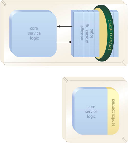
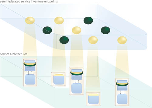
Figure 9.2 illustrates how primary services existing as Web services can co-exist with secondary services existing as components. Both primary and secondary service levels represent official endpoints as part of a semi-federated service endpoint layer.
There are significant risks when applying this pattern as explained in the upcoming Impacts section. To minimize this impact, the following guidelines are recommended:
• Contract Centralization (409) must always be respected, which means that services based on the primary protocol must be accessed via the primary protocol when invoked by secondary services. In the case of Web services, this require that component-based services not directly access the underlying components or resources of Web services-based services.
• Consider some or all services in the secondary level as transition candidates. If this pattern was chosen due to a lack of maturity in the primary protocol, then secondary services can be earmarked for an upgrade to the primary level once the technology has sufficiently evolved.
• During a transitional period, use Concurrent Contracts (421) to enable a service to be accessible via either protocol. This way, it can begin to interoperate using the primary protocol while continuing to support consumers that rely upon the secondary protocol.
• Apply Redundant Implementation (345) wherever feasible in support of secondary services. This is especially relevant when component-based secondary services are primarily composed by the core service logic of Web services-based services to avoid remote communication. Redundant Implementation (345) will support the autonomy of both primary and secondary service levels.
Note that some secondary services may never transition and therefore always remain based on the secondary protocol. This may be due to the nature of their functionality or the convenience of keeping them for intra-service composition purposes only.
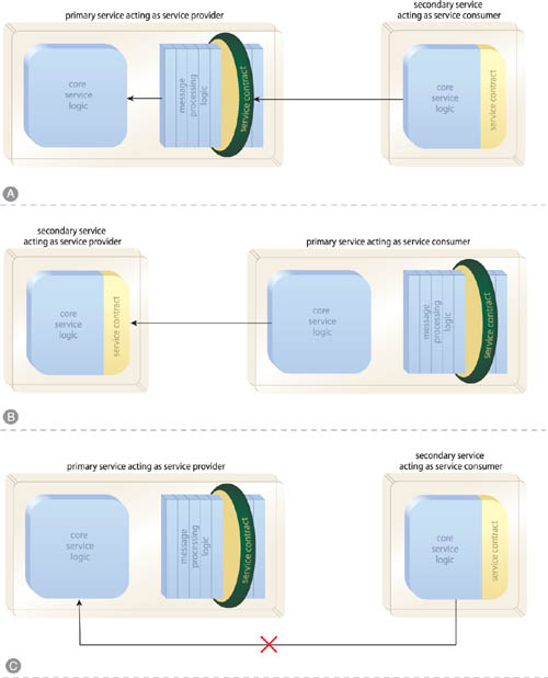
As shown in Figure 9.3, the first guideline in the previous list establishes some ground rules as to how primary and secondary services should and should not interact.
Figure 9.3 Regardless of protocol, all services must invoke each other via their official service contracts (A, B). Bypassing the contract may seem convenient when the underlying service logic of the primary service supports the same protocol as the secondary service (C), but it is an anti-pattern that will eventually inhibit the application of this pattern and further weaken the overall service inventory foundation.
The key requirement to successfully applying this pattern is for services to continue adhering to Standardized Service Contract, Service Loose Coupling, and Service Abstraction design principles to avoid many of the negative, indirect coupling types that can lead to governance problems.
Note
An alternative approach to applying this pattern is to limit the secondary protocol to utility services only. When working with Web services as the primary protocol and a native component technology as the secondary protocol, this approach can reduce the size of Web service compositions by limiting them to business services. These business Web services can then compose component-based utility services, as required.
Although this pattern description is focused on components and Web services as implementation mediums, REST services and the use of HTTP as an application protocol provide another viable option. To learn more, visit SOAPatterns.org and read up on the REST-inspired patterns currently in development.
This design pattern must be used in moderation. It imposes some significant architectural constraints and sacrifices that need to be carefully assessed before committing to an architecture based on primary and secondary protocols.
For example:
• The use of Concurrent Contracts (421) to provide secondary services with two interfaces while they are being transitioned from secondary to primary status can lead to overly complex governance requirements. If this pattern is applied to a large service inventory with a large percentage of secondary services, the transition effort may be unwieldy.
• The repeated application of Redundant Implementation (345) in support of secondary services can rapidly increase infrastructure budgets and the overall configuration management effort required to keep all deployments of a given service in synch.
• Depending on which technologies are chosen for primary and secondary protocol levels, this pattern may limit the application of other key design patterns, such as Canonical Schema (158) and Schema Centralization (200).
• The examples in this chapter were focused on Web services comprised of components that shared the same protocol technology as the component-based services. If this pattern is applied to primary and secondary service levels that are based on disparate protocols, it will introduce the need for the constant application of Protocol Bridging (687).
• This pattern introduces the on-going risk of imposing too much technology coupling upon consumers, thereby making plans to migrate to a fully federated service inventory difficult to fully attain.
There are concrete benefits to carrying out this design pattern in the right way, but it introduces a whole new dimension to a service-oriented architecture adoption, and the associated risks need to be planned for in advance.
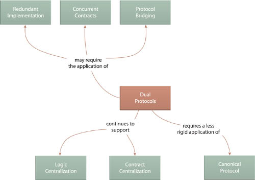
The extra requirements that come with applying Dual Protocols often need to be addressed with the application of additional supporting patterns, such as Redundant Implementation (345), Concurrent Contracts (421), and Protocol Bridging (687).
Although this pattern fundamentally preserves the goals of Logic Centralization (136) and Contract Centralization (409), it ends up augmenting the default approach of carrying out Canonical Protocol (150) by essentially allowing two canonical protocols.
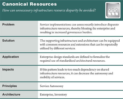
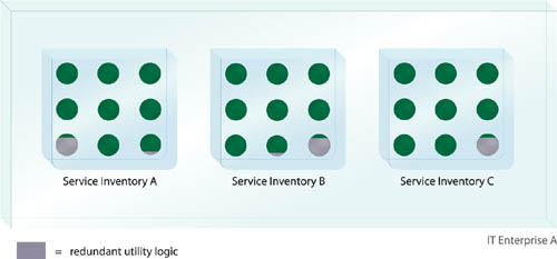
Services delivered without architectural design standards or developed outside of an organization (as part of an outsourced project, for example) run the risk of introducing disparate yet still redundant infrastructure resources. This can bloat an inventory architecture and unnecessarily introduce complexity, leading to increased administration and operational costs and other governance burdens associated with maintaining a bloated enterprise environment (Figure 9.5).
Utility Abstraction (168) is often used to wrap common infrastructure resources and then make them available via a standardized contract to the rest of the service inventory. When this is not possible, common resources are identified and standardized in order to maintain consistency across service designs and throughout the inventory in general (Figure 9.6).
This pattern is specifically focused on infrastructure products, platforms, and extensions (collectively referred to as “resources”) that provide common features useful to multiple services. These infrastructure-centric resources are essentially identified and standardized.
It is important to not allow the application of this pattern to inhibit the Vendor-Neutral design characteristic (introduced in Chapter 4) of a service inventory architecture. Therefore, the nature of the design standards that result from this pattern is preferably such that the chosen resource becomes the default option for a given requirement or purpose. This leaves the flexibility for alternatives to be considered if requirements exist that cannot be adequately fulfilled by the standardized resource.
The repeated application of this pattern can lead to a natural tendency to want to share and reuse standardized products for cost or development efficiency purposes. This may often be warranted, but it can also inadvertantly reduce the autonomy of services beyond what it should be.
This pattern relates to others primarily as a regulatory influence. Design patterns that implement new architectural resources or extensions are encouraged to avoid introducing disparate infrastructure-related products and technologies that fulfill the same overall purpose. This affects all of the patterns listed at the top of Figure 9.7.
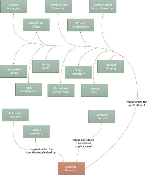
The end result of applying Canonical Resources is similar to enforcing an enterprise design standard, which is why Canonical Protocol (150) can be viewed as a variation of this pattern focused only on communication technologies.
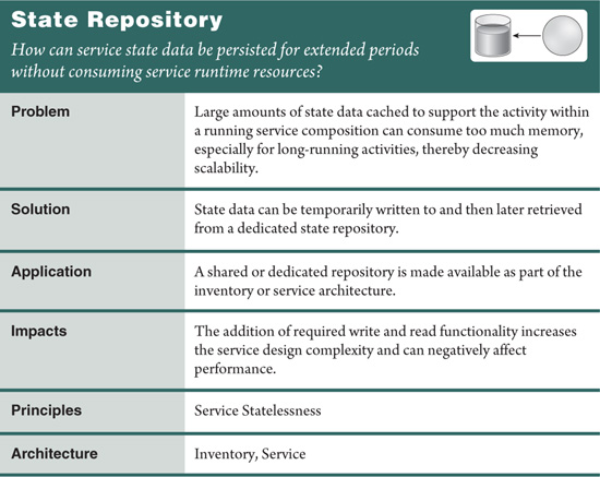
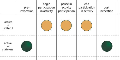
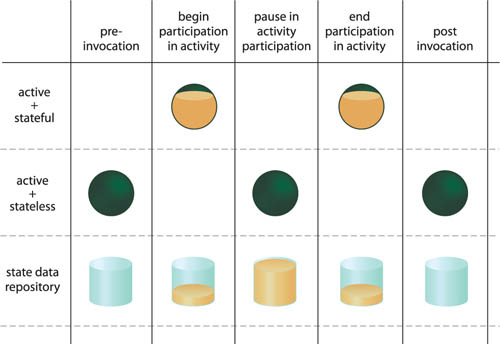
It is often necessary to retrieve and cache bodies of data to which service capabilities require repeated access during the course of a service activity. However, some complex compositions introduce extended periods of processing during which this data is not required. While idle, this cached data continues to be stored in memory and consumes runtime resources (Figure 9.8).
This excess consumption can severely compound during periods of high concurrent usage, depleting the overall available runtime service. As this occurs repeatedly with different services throughout an inventory, overall scalability thresholds can decrease.
A state repository is established as an architectural extension made available to any service for temporary state data deferral purposes (Figure 9.9). This alleviates services from having to unnecessarily keep state data in memory for extended periods.
Note
See the Measuring Service Statelessness section in Chapter 11 of SOA Principles of Service Design for a detailed description of state data and additional scenarios involving state data repositories.
Typically, a dedicated database is provided for state deferral purposes. The database is located on the same physical server as the services that will be utilizing it, so as to minimize runtime performance overhead associated with the writing and retrieval of the data. Another approach is to create dedicated tables within an existing database. Though less effective, this still provides a state deferral option suitable for temporary data storage.
Alternatives to State Repository include Stateful Services (248) and State Messaging (557), which can be considered especially when the state data does not need to be persisted over long periods of time. Howver, it is also fairly common for State Repository to be used in conjunction with these patterns to provide more flexible (albeit more complex) state management mechanisms that may be especially suitable for providing customized state deferral options for different types of state data.
Incorporating the state deferral logic required to carry out this pattern can increase service design complexity, leading to more development effort and expense.
Although State Repository can improve scalability, having to write data to and retrieve data from a physical hard drive generally imposes more runtime performance overhead than having to carry out the same functions against data stored in memory. For service activities with strict real-time performance requirements, this state deferral option needs to be carefully assessed.
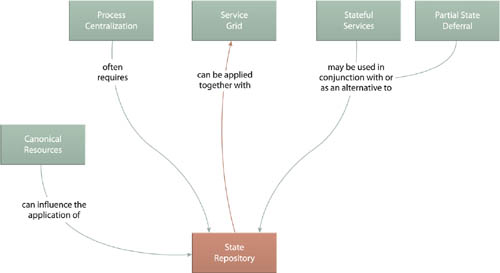
Establishing a state management system via State Repository naturally relates to other state deferral-related patterns, such as Stateful Services (248), Partial State Deferral (356), State Messaging (557), and Service Grid (254). All of these patterns may end up using the central state database introduced by this pattern. Canonical Resources (237) can further help ensure that no one inventory will have more than one type of state management database unless absolutely required.
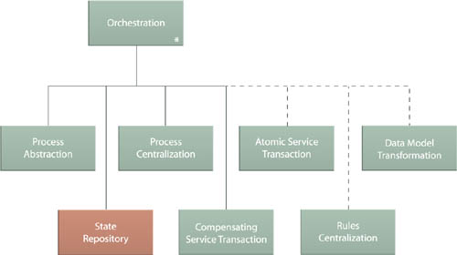
Process Centralization (193) will almost always require the application of this pattern to provide a means of persisting state data associated with the many business processes that orchestration environments are required to execute and manage (especially in support of long-running processes). This is why State Repository is one of the core patterns that comprise Orchestration (701).
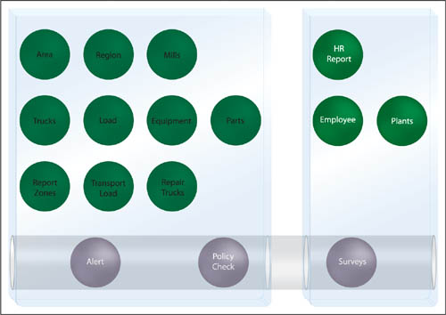
Case Study Example
The Alleywood Policy Check service (Figure 9.12) is responsible for issuing periodic queries against public FRC Web services that provide access to the most current policy information. These queries help confirm that current policies used by Alleywood are still valid or have changed.
Figure 9.12 The Policy Check service issues a query against the first FRC service (1) and then writes the results to the state repository (2) before requesting data from the next FRC service (3). That information is then also written to the state repository (4), and after the Policy Check service retrieves the last batch of data from the third FRC service (5), it retrieves the data from the state repository (6) and assembles the requested policy report (7).
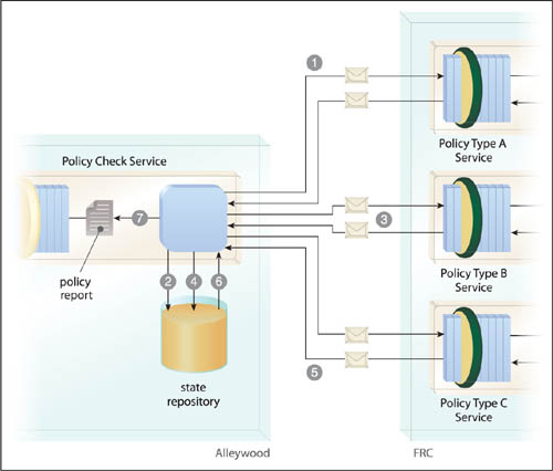
The FRC exposes three separate Web services that provide report-style data for different policy types. Alleywood, being a larger-sized company, is required to remain in compliance with all three types of policies. This service therefore needs to query each FRC service before it can produce a consolidated report.
Query times can vary, depending on concurrent usage of the FRC services and the databases they access. Sometimes it can take minutes to receive a response, and other times the response times out or fails altogether. The initial version of the Policy Check service had many problems due to these irregular access conditions. It became one of the most unreliable parts of the Alleywood service inventory and consumed unusually high amounts of memory.
As a result, the Policy Check service is refactored to write each batch of data it receives to a state repository. Even if access to an FRC service fails, the data collected so far is preserved in this database, while the Policy Check service retries its access. It then continues to wait until it has received all the information it needs, at which point it retrieves all of the data back from the state repository and merges it into the requested report.
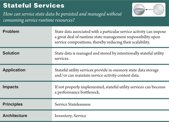
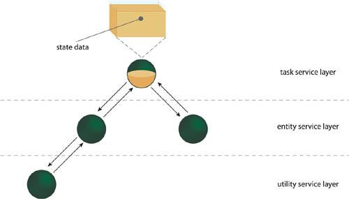
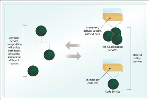
The coordination of large service activities requires the constant management of state data. Placing the burden of retaining and processing this data upon business services increases their individual memory consumption as well as the duration for which they are required to remain stateful (Figure 9.13).
Intentionally stateful utility services are created to provide regular state deferral and storage functions and/or to provide runtime coordination functions to manage the flow and participation of service activities. This alleviates the need for any one business service from having to retain or manage state data for extended periods (Figure 9.14).
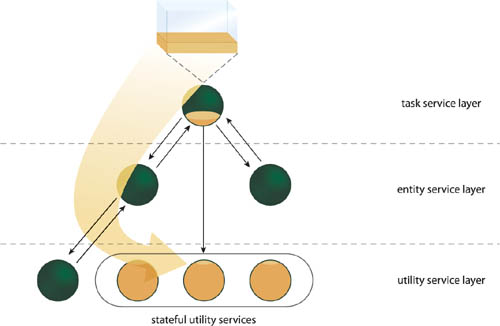
This pattern is commonly applied in two ways:
• The stateful utility services provide state management deferral functions that are explicitly used by other services as required.
• The stateful utility services are part of a service activity management framework (such as WS-Coordination) within which they act as runtime activity coordinators.
Either way, what distinguishes services dedicated to state management is that they are deliberately stateful parts of the enterprise. Therefore, these specialized services intentionally violate the Service Statelessness principle so as to support its application in other services.
In high concurrency situations, stateful utility services can be required to manage numerous service activities and activity instances at the same time. If they are not supported by the proper infrastructure, the overall performance and scalability of the service inventory as a whole can be compromised, thereby undermining their purpose.
Also the use of stateful utility services adds more “moving parts” to a given service composition, thereby increasing its complexity.
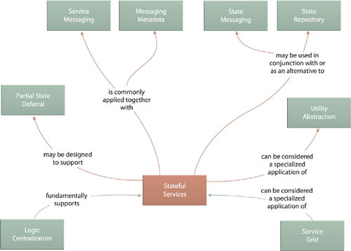
This pattern establishes a specialized variation of the utility service and is therefore related to Utility Abstraction (168). Some implementations may still require a state management database behind the scenes, leading to the need to also apply State Repository (242) and the option to utilize State Messaging (557) to temporarily off-load state data is also possible. Additionally, both State Repository (242) and State Messaging (557) represent viable alternatives to Stateful Services altogether.
When stateful utility services exist as Web services, Service Messaging (553) is required for basic communication, and Messaging Metadata (538) provides a means of supplementing state data deliveries with additional activity details. As further explored in the next pattern description, Stateful Services also relates closely to Service Grid (254).
Case Study Example
The transaction framework described in the case study example for Canonical Resources (237) established WS-Coordination as a standardized context management system intended to facilitate all ACID-style transactions within the FRC service inventory.
Under the covers this framework is comprised of a set of stateful utility services that are pre-defined as part of the WS-Coordination specification. These services require that regular services participating in a transaction first register for the transaction and then communicate to them the status of their involvement. Once a service has completed its participation, it de-registers itself from the transaction.
The rules by which the stateful WS-Coordination services manage transactions are defined separately in the WS-AtomicTransaction specification. For example, a voting mechanism is introduced whereby participating services are polled as to whether their contribution to a given transaction was successful or not. Services can respond with “Commit” or “Abort” messages that indicate their status. If just one “Abort” message is received (or if one vote is missing from the registered services), then the transaction is in fact aborted, and a “Rollback” message is sent to all participants.
Together, WS-Coordination and WS-AtomicTransaction provide an industry-standard transaction management framework for the FRC that manages service activity data (referred to as context information) on behalf of other custom services. This alleviates custom FRC services from having to provide some of the logic required to coordinate service activity-specific details.
However, after working with this framework, it is soon discovered that there is an additional opportunity to delegate state management-related processing. Specifically, FRC architects notice redundant logic creeping into a number of entity services required to work with a set of code lists common to the forestry industry. Often these code lists need to be placed into memory and then repeatedly accessed as transactions are carried out.
FRC architects would like to see this type of state data managed separately by stateful utility services. Because the WS-Coordination system services are pre-defined, architects are not comfortable augmenting them to incorporate this new functionality. Instead, they opt to create a custom Code service that will be used to complement the WS-Coordination framework by allowing all services participating in transactions to read and write code lists (Figure 9.16).
Note
The preceding case study example used the WS-Coordination framework as an example of a framework that supports the application of this pattern. The actual mechanics behind cross-service transactions are further explained in the pattern description for Atomic Service Transaction (623).
Conventional state deferral mechanisms have thresholds that can impede the usage potential of services.
For example:
• When services defer state data to a central database, as per State Repository (242), it can result in performance bottlenecks relative to the extent that the repository is shared and the available resources of the underlying infrastructure. Furthermore, a state database can become a single point of failure for all services that rely on it (Figure 9.17).
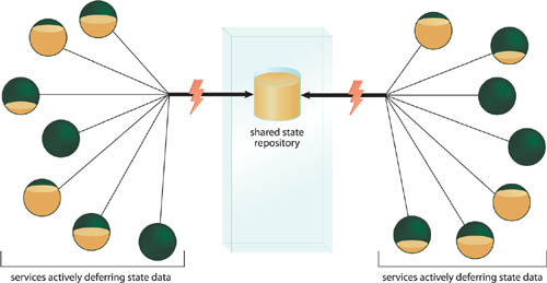
• When services defer state data to utility services, as per Stateful Services (248), failover concerns are even greater than with State Repository (242) because the state data is kept in memory and may not be recoverable after a failure condition. Additionally, stateful utility services may become performance bottlenecks due to an absence of built-in load balancing functionality.
In some platforms, State Repository (242) and Stateful Services (248) can be supported by infrastructure extensions that provide failover. However, these extensions are often based on “failure and restart” approaches that involve a transaction manager-like rollback and recovery. While this provides some level of fault tolerance, it will typically result in loss of data, runtime disruption and exceptions, and may further require manual intervention by humans.
Deferred service state data is persisted and stored by a dedicated collection of grid services—stateful services which are part of a services-based grid platform and act as an extension of the infrastructure.
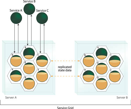
Within this platform, multiple, redundant instances of the grid services are constantly available and remain consistently synchronized. This allows each grid service to provide its own individual memory cache that is replicated across multiple redundant instances that reside on and are load balanced across different server machines (Figure 9.18). Additional grid service instances can be further spawned, as required.
The resulting environment can establish high scalability and fault tolerance of deferred state data throughout an entire service inventory and even across multiple inventories.
How Service Grid is actually implemented can vary, depending on the specific platform or vendor product that is chosen. A common process is for a custom service to pass state data to a grid service, which then responds with a unique identifier (called a state key) that represents the body of state data. The service receives and holds onto the state key while it remains active, and can then use this key to access and retrieve some or all of the previously deferred state data.
Note
The notion of a state key also forms the basis of a separate pattern that allows the same body of state data to be shared across multiple services and service compositions. This and other specialized patterns associated with Service Grid are being published at SOAPatterns.org and will further be documented in a separate book by David Chappell.
Behind the scenes, the inner mechanics of the service grid ensure that whatever state data is received is constantly duplicated via distributed, redundant grid service instances. If the custom service makes a change to the state data or retrieves portions of it, these events are replicated to the corresponding redundant grid service instances so that they remain synchronized.
Should a grid instance fail, any one of its counterparts assumes its place and continues to make the state data available to the original custom service. Intelligent load-balancing functionality may be present to direct deferral or retrieval requests from the custom service to the grid service instance residing on the physical server that is being used the least at that point in time. Furthermore, advanced grid computing extensions can be added to offload the execution of service logic into the service grid in order to reduce network data serialization latency between custom and grid services.
Throughout all of this, regular custom services that interact with grid services are shielded from the inner workings of the service grid platform and may simply view grid services as generic stateful utility services. A service grid implementation can include or be further extended with State Repository (242) for long-term state storage requirements.
This pattern is especially effective in large-scale service inventories or across multiple inventories because of its horizontal scalability potential. It is not uncommon for service grid implementations to be comprised of dozens or hundreds of servers. The constant availability of the state deferral mechanism provided by the grid services reduces the resource impact on regular custom services, thereby increasing their scalability as well. When broadly utilized, this load sharing dynamic can establish a service grid as a prevalent and intrinsic part of the overall service-oriented enterprise.
The need to add multiple physical servers, coupled with product license costs and additional required infrastructure extensions can make the adoption of Service Grid costly. It may be further desirable for a service grid to be isolated on its own high-speed network in order to accommodate the constant cross-server synchronization that needs to occur.
As a result of the required expansion of infrastructure, grid-based environments will naturally increase the governance burden of one or more service inventory architectures, resulting in on-going operational effort and costs.
The application of Service Grid essentially results in the application of Stateful Services (248), but State Repository (242) can also become part of a grid platform, depending on its configuration. Partial State Deferral (356) is generally supported by grid services, that may further require the use of Messaging Metadata (538) to exchange state keys.
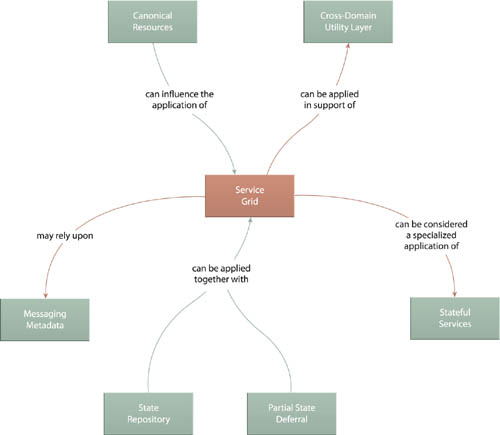
When positioned as an enterprise-level resource, Service Grid can establish infrastructure that can be leveraged by multiple service inventories. Because of the utility-centric nature of grid services, this can effectively enable or extend the application of Cross-Domain Utility Layer (267).
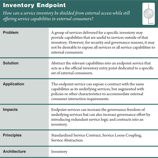
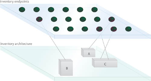
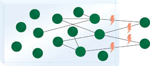
As described in Chapter 4, a service inventory represents a collection of independently standardized and governed services. When opportunities arise for services to share their capabilities with service consumers that reside outside of the inventory (whether they are consumers within the same organization but part of a different inventory or consumers external to the organization itself), interoperability, privacy, and security-related concerns often arise, making the option of simply exposing internal inventory services to external consumers less than desirable (Figure 9.20).
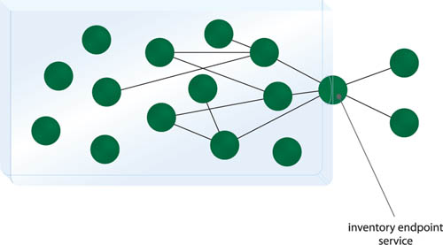
A special type of intermediary service is positioned as the official service inventory entry point for consumers external to the inventory that need to access native services within the inventory (Figure 9.21). This endpoint service can be configured to accommodate consumer interaction preferences and can further contain broker and mediation logic to help facilitate communication with internal inventory services.
By abstracting capabilities from a collection of services into a single contract, services positioned as endpoints for an inventory offer several benefits, including:
• Increased governance freedom for the underlying services, as they can be changed and extended without affecting the endpoint service contract. Even if underlying service functionality needs to be altered, logic could be introduced into the endpoint service to accommodate for the changes so that external consumers remain unaffected and unaware.
• The endpoint service contract can be fully customized to accommodate the external consumer programs. This allows for the addition of data and security constraints, policy assertions and alternatives, and even the support of additional transport protocols unique to the consumer interaction requirements. By abstracting these implementation requirements into a single service, underlying inventory services are not required to change.
• A separate endpoint service can be created for each group of external consumers. This allows the aforementioned customization to be specific to a range of consumer types. For example, one endpoint service can be created for consumers from a different domain inventory, and a separate endpoint service can be positioned for consumer programs residing outside of the organization itself.
• Beyond providing alternative contract representation for inventory services, an endpoint service can also provide Protocol Bridging (687) for consumers that use disparate protocols or data exchange technologies.
Endpoint services are typically single-purpose with non-agnostic functional contexts and are therefore generally classified as task services. Some organizations, however, prefer to consider the endpoint service as its own service model, especially since endpoint services may be required to encapsulate inventory-specific task services.
Although they are often delivered and owned by the custodian of the inventory for which they act as endpoints, they are not always considered members of that inventory because they are required to conform to different design standards and are not made available for native compositions. Endpoint services are often literally maintained at the periphery of inventory boundaries. Therefore, the first step to working with endpoint services is to establish an effective ownership structure that will allow these services to evolve with both their underlying inventories and their consumers.
For endpoint services created to interact with consumers from external organizations, special implementation requirements are almost always needed. These can include the need for deployment within a DMZ on an isolated server and various infrastructure extensions associated with security and sometimes scalability.
The core service logic for an endpoint service is generally comparable to logic shaped by Service Façade (333) in that it is mostly comprised of routines that relay data requests and responses to and from the external consumers and the underlying inventory services. However, when endpoint services are required to provide new policies or enforce new constraints, additional logic is needed. Furthermore, endpoint services are commonly relied upon to act as brokers by carrying out Data Model Transformation (671), Data Format Transformation (681), and even Protocol Bridging (687).
While Inventory Endpoint increases the freedom with which inventory services can be evolved and governed over time, they do result in the introduction of new services and service contracts that will need to be maintained as an addition to the service inventory itself. This governance responsibility and the associated ownership issues that need to be addressed can introduce a significant amount of cost and effort because of the on-going maintenance required to keep them in synch with internal service and external consumer requirements. This pattern may even lead to the need for a new IT group altogether (especially if multiple endpoint services are produced).
The use of Inventory Endpoint raises both contract design and architectural issues, which therefore relates this pattern to service design patterns, such as Service Façade (333) and Concurrent Contracts (421), as well as implementation-related patterns like Composition Autonomy (616) and Redundant Implementation (345).
In fact, this pattern can sometimes appear as a specialized variation of Concurrent Contracts (421) in that it introduces the need to establish a new services that functionally overlap with existing ones (and therefore also violates Service Normalization (131) to an extent).
As shown by the relationships to the three patterns that comprise Service Broker (707) on the right side of Figure 9.22, one of the most common responsibilities of the inventory endpoint service is to overcome the communication disparity between inventory services and external consumers. This is simply because consumers outside of the inventory are generally subject to different design standards and conventions.
Note
The application of Enterprise Service Bus (704) will also often naturally apply Inventory Endpoint by establishing external endpoints that encapsulate broker and mediation logic. The distinction with this pattern is that the endpoint is specific to a service inventory.
Case Study Example
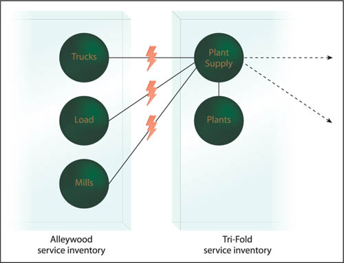
A new Tri-Fold service composition is assembled to automate the recently modeled Plant Supply business process. This is a complex composition involving eight services and a great deal of activity management. To further complicate the design, the Plant Supply task service is required to access the following three services that reside within the Alleywood service inventory:
• a Trucks service responsible for processing information related to the delivery of materials to the plants
• a Load service that provides functionality pertaining to “in transport” materials being delivered
• a Mills service that represents the origin of delivered loads
The initial composition design has the Plant Supply task service invoking each of the three Alleywood services individually, thereby being subject to remote access performance challenges and data model transformation requirements, in addition to further disparity in how security and activity meta data is represented (Figure 9.23).
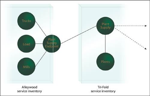
Once performance calculations are added up and after the design complexity of this proposed composition is mapped out, the approach is rejected. Instead, by applying Inventory Endpoint, a new service is introduced into the Alleywood inventory called the Plant Supply Endpoint service.
This service establishes a contract custom designed for the Tri-Fold Plant Supply service so that no external transformation is required (Figure 9.24). Internally, this service performs all necessary conversion and also encapsulates the required composition logic to interact with the Alleywood Trucks, Load, and Mills services.
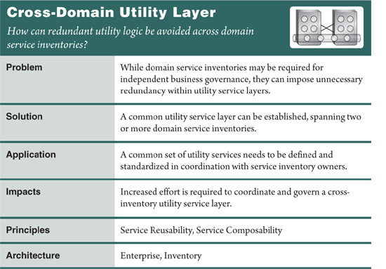
The primary reason for enterprises to proceed with multiple domain service inventories is to allow for the governance of individual inventories by separate groups that represent the respective domains. More often than not, these inventories are associated with organizational business domains, and the governance issues pertain to the design and evolution of business service layers. The rationale is to tolerate the use of different standards and increased redundancy across business service layers within domains for the benefit of acheiving manageable SOA adoption and governance.
However, the utility layers within these domains have no ties to business models, and often the corresponding utility services encapsulate enterprise resources that are common to all domains. As a result, some utility logic created for one domain will tend to be functionally similar (or even identical) to others. The resulting redundancy and design disparity within multiple utility service layers (across different inventories) is therefore wasteful and unnecessary (Figure 9.25).
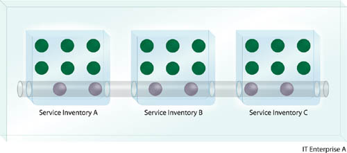
A common utility service layer is positioned for use by multiple domain service inventories, establishing a centralized collection of normalized (non-redundant) utility services accessible to and reusable by services across domains (Figure 9.26).
Figure 9.26 A cross-domain utility service layer establishes a set of common services that address broad, cross-cutting concerns. Notice how a smaller quantity of utility services is required (compared to Figure 9.25) due to reduced redundancy.
It is recommended that in addition to design standards that require domains to use utility services, standard processes also exist across domains to allow for the identification and reuse of cross-domain utility services. This service layer is very much a part of the enterprise architecture and should therefore be established prior to domain service inventory definition.
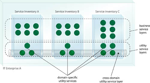
Note that a cross-domain utility service layer does not need to replace a domain inventory’s utility layer in its entirety. Domain-specific utility services can be defined as required and then further complemented by cross-domain utility services (Figure 9.27).
One of the reasons to create domain service inventories is to allow for each domain to evolve independently, which is a more manageable approach for some organizations. Requiring that all inventories use the same common set of utility services reduces this independence somewhat.
It furthermore complicates the overall governance processes that need to be in place; instead of domain-specific groups that own and maintain domain services, there may now need to be an enterprise governance group that owns the cross-domain utility service layer and ensures that these services are properly utilized within each domain.
Note also that if service inventory domains are based on geographical boundaries, or if domains consist of vastly disparate technical environments, the governance logistics for applying this pattern can prove difficult.
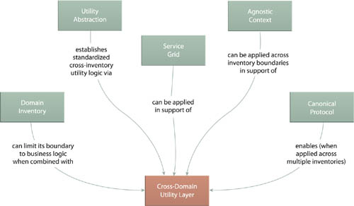
Cross-Domain Utility Layer changes the complexion of a service-oriented enterprise by impacting multiple domain inventory architectures and therefore has naturally close relationships with Domain Inventory (123), Utility Abstraction (168), and Agnostic Context (312), while also providing an opportunity to establish broad baseline interoperability in support of Canonical Protocol (150).
Case Study Example
When both Alleywood and Tri-Fold service inventory blueprints are completed, they are reviewed by the McPherson Enterprise Group. Although each is comprised of well-defined, normalized collections of services, it is evident that there is significant functional redundancy, especially within the utility service layers. In fact, the utility logic defined is almost identical, primarily due to these services being positioned for access to shared resources.
The reasons behind splitting the original enterprise service inventory into separate physical domains were primarily rooted within resource and governance issues associated with business concerns. However, there is no real objection to applying this pattern to establish an enterprise-wide utility service layer. Although the initial layer is comprised of all utility services either inventory needs (Figure 9.29), Alleywood and Tri-Fold will be able to create inventory-specific utility services as well.