

Singled out in this chapter are some of the more common and important combinations of the patterns documented in previous chapters. Each such combination is classified as a compound design pattern.
A “composite” is generally something that is comprised of interconnected parts. For example, you could legitimately refer to a service composition as a composite of services because the individual parts need to be designed into an aggregate in order to act as a whole. A “compound,” on the other hand, can simply be considered the result of combining a specific set of things together. A chemical compound consists of a combination of ingredients that result in something new when mixed together.
The patterns in this chapter are referred to as “compound patterns” because they document the effects of applying multiple patterns together. One of the most interesting parts of this exploration is that certain combinations of patterns result in design solutions that are already quite common, such as with Enterprise Service Bus (704) and Service Broker (707).
Every pattern profile in the previous chapters included a Relationships section that provided some insight into inter-pattern dependencies and how the application of one pattern can affect another.
Compound patterns are also about relationships, but in a different way. The patterns that comprise a compound pattern have a relationship with the compound pattern itself. Whether these patterns have dependencies with or impact each other is immaterial. When studying them as members of a compound pattern, we are only interested in the results of their combined application.
When we discuss the notion of combining patterns into compounds, it is important to clarify how patterns can be combined.
A compound pattern can represent a set of patterns that are applied together to a particular program or implementation in order to establish a specific set of design characteristics. This would be referred to as joint application.
The compound patterns with patterns that are jointly applied are:
Alternatively, the patterns that comprise a compound pattern can represent a set of related features provided by a particular program or environment. In this case, a coexistent application of patterns establishes a “solution environment” that may be realized by a combination of tools and technologies.
Compound patterns comprised of patterns that coexist to establish such an environment are:
• Orchestration (701)
• Enterprise Service Bus (704)
• Service Broker (707)
• Canonical Schema Bus (709)
The notation used to express compound patterns comprised of patterns that are jointly applied versus those applied in a coexistent manner differs, as shown in Figure 22.1.

Even though this chapter classifies a set of patterns as “compound patterns,” it is important to note that just about any pattern can turn out to be a compound pattern. Every one of the other patterns described in this book can be decomposed into a set of more granular patterns. Their joint or coexistent combination then results in the original pattern, thereby also making it a compound pattern.
For example, Chapter 18 establishes Asynchronous Queuing (582) and Intermediate Routing (549) as providing fundamental, messaging-related solutions. In the upcoming ESB Architecture for SOA book, a set of more granular queuing and routing design patterns are described that can be considered as collectively representing Asynchronous Queuing (582) and Intermediate Routing (549) as compound patterns.
The reason this perspective is important is because whether or not a pattern is labeled as being a compound pattern is always relative. It is just a matter of the granularity at which the pattern is documented in relation to other patterns in the same catalog.
As a result, the compound patterns in this chapter are only classified as such because of the granularity at which the rest of the patterns are defined in this book. In a different publication or context, these patterns may be classified differently.
By Thomas Erl, Brian Loesgen
An orchestration platform is dedicated to the effective maintenance and execution of parent business process logic. Modern-day orchestration environments are especially expected to support sophisticated and complex service composition logic that can result in long-running runtime activities.

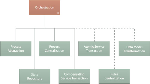
The Orchestration compound pattern is comprised of the following design patterns:
• Process Abstraction (182) is responsible for separating non-agnostic logic from agnostic logic, which forms the basis of the parent composition logic that resides within the orchestration platform and is executed by the orchestration engine.
• Process Centralization (193) limits the physical distribution of abstracted process logic into one (or a group) of locations. This allows for the centralized maintenance of parent composition logic via specialized tools provided by the orchestration platform.
• State Repository (242) enables orchestration environments to support long-running service activities by providing a native state management repository that can be leveraged as a state deferral mechanism.
• Compensating Service Transaction (631) further supports long-running processes by allowing parent composition logic to be supplemented with compensation sub-processes that address exception conditions.
Figure 22.3 illustrates how the combination of the first three of these patterns establishes an orchestration environment from an implementation perspective, and Figure 22.4 highlights how this base platform is commonly extended with features that correspond to design solutions provided by other patterns covered in this book.

By Thomas Erl, Mark Little, Thomas Rischbeck, Arnaud Simon
An enterprise service bus represents an environment designed to foster sophisticated inter-connectivity between services. It establishes an intermediate layer of processing that can help overcome common problems associated with reliability, scalability, and communications disparity.
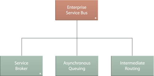
Enterprise Service Bus is considered a compound pattern comprised of the following core patterns that coexist to provide a base set of interoperability-enablement features:
• Service Broker (707), which itself is a compound pattern that consists of a set of integration-centric patterns used to translate between incompatible data models, data formats, and communication protocols.
• Asynchronous Queuing (582), which establishes an intermediate queuing mechanism that enables asynchronous message exchanges and increases the reliability of message transmissions when service availability is uncertain.
• Intermediate Routing (549), which provides intelligent agent-based routing options to facilitate various runtime conditions.
How this set of patterns can be combined to establish a middleware-based messaging mechanism is illustrated in Figure 22.6. The expanded pattern hierarchy shown in Figure 22.7 reveals additional patterns that are common, optional extensions of Enterprise Service Bus.
Figure 22.6. A message undergoing various processing steps carried out by an ESB in order to successfully transform and deliver the message contents to their destination. Note that this scenario depicts all three solutions working in tandem to process a single message. Other message transmissions may not require all of this functionality. It is simply the coexistence of specific patterns that constitutes an ESB.
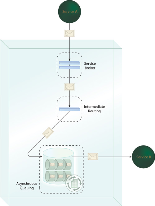
Figure 22.7. The expanded Enterprise Service Bus pattern hierarchy showing the core patterns (top left) and patterns that commonly extend the base ESB (top right), plus the patterns that comprise Service Broker (707) (bottom).

By Mark Little, Thomas Rischbeck, Arnaud Simon
Broker functionality has been a common part of middleware platforms, providing multi-faceted runtime conversion features that enable integration between disparate systems.

The Service Broker compound pattern is comprised of Data Model Transformation (671), Data Format Transformation (681), and Protocol Bridging (687). Although all of these patterns are used only out of necessity, establishing an environment capable of handling the three most common transformation requirements can add a great deal of flexibility to a service-oriented architecture implementation, and also has the added bonus of being able to perform more than one transformation function at the same time.
Broker-related features are a fundamental part of ESB platforms, which is why this pattern exists as part of Enterprise Service Bus (704), as depicted in Figure 22.9.
Figure 22.9. The Service Broker pattern hierarchy itself is nested within the hierarchy of Enterprise Service Bus (704).

By Clemens Utschig-Utschig, Berthold Maier, Bernd Trops, Hajo Normann, Torsten Winterberg, Thomas Erl
While Enterprise Service Bus (704) provides a range of messaging-centric functions that help establish connectivity between different services and between services and resources they are required to encapsulate, it does not inherently enforce or advocate standardization. In fact, it can be argued that the native broker functions provided by some ESB platforms can discourage standardization by making it “too convenient” to integrate disparate services.

Building upon the platform established by Enterprise Service Bus (704), this pattern adds Decoupled Contract (401) and Contract Centralization (409) together with Canonical Schema (158) to position entry points into the logic, data, and functions offered via the service bus environment as independently standardized service contracts (Figure 22.11).

Canonical Schema Bus restricts entry to points to centralized and canonical service contracts and further limits the use of Service Broker (707) related patterns to intra-service transformation requirements. This places the onus of having to conform to standardized contracts upon any service or program that needs to consume them. The ultimate goal of this pattern is to promote and enforce contract-level standardization throughout a service inventory.
As important as it is to clearly differentiate Logic Centralization (136) from Contract Centralization (409), it is equally important to understand how these two fundamental patterns can and should be used together:
• While Logic Centralization (136) asks designers to build consumer programs that only invoke designated services when specific types of information processing are required, it does not address how this logic is to be accessed.
• While Contract Centralization (409) asks designers to build consumer programs that access a service only via its published contract, it does not indicate which services should be accessed for specific purposes.

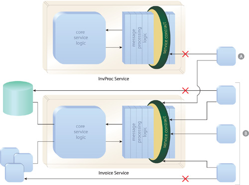
Applying these two patterns to the same service realizes the Official Endpoint compound pattern (Figure 22.13). The repeated application of Official Endpoint supports the goal of establishing a federated layer of service endpoints, which is why this compound pattern is also a part of Federated Endpoint Layer (713).
Figure 22.13. As per Logic Centralization (136), a consumer program (A) requiring invoice functionality can only access the Invoice service, which is the designated service for this logic. As per Contract Centralization (409), consumer programs (B) can only access the Invoice service via its centralized contract. The combination of these patterns establishes the Invoice service as an “official” endpoint.
Federation, within the context of this compound pattern (and also as it relates to the Increased Federation strategic goal explained in Chapter 4), represents a state where different services combine to form a united front (Figure 22.15), while allowing their respective, underlying environments to continue to be governed independently (Figure 22.16).


Figure 22.16. If you were to tip Figure 22.13 over on its side, you might see how, though providing a united front, the federated endpoints each abstract different service implementations.

Federation is an important concept in service-oriented computing. It represents the desired state of the external, consumer-facing perspective of a service inventory, as expressed by the collective contracts of all the inventory’s services. The more federated and unified this collection of contracts (endpoints) is, the more easily and effectively the services can be repeatedly consumed and leveraged.
The various patterns that make up this compound pattern are applied as follows:
• Each service positions the service contract as its sole entry point for a distinct functional boundary, as per Contract Centralization (409) and Logic Centralization (136) that comprise Official Endpoint (711).
• Service Normalization (131) is applied to the inventory (most likely via the prior definition of a service inventory blueprint) to ensure that no functional boundaries overlap.
• The service contracts (endpoints) themselves are standardized so that they support the same primary protocol, share the same data models for business documents, and express themselves consistently, as per Canonical Protocol (150), Canonical Schema (158), and Canonical Expression (275), respectively.
This compound pattern is simply comprised of the combined application of the following three fundamental inventory design patterns associated with Service Layers (143).

The Three-Layer Inventory exists because the combined application of these three patterns is recommended for the following reasons:
• Each of the three abstraction patterns is proven to represent a common classification of service logic. The combined logic required to automate business processes for most organizations can be represented by these three service layers.
• The service layers are fully complementary in that each layer is distinct and does not overlap with another. As explained in the introductory section of Chapter 7, the three layers establish an effective separation of non-agnostic and agnostic plus business-centric and non-business-centric logic.
• The service models upon which these service layers are based are generic. This not only makes them common, but also customizable. For example, a typical variation of the utility service model is a state management service, as per in Stateful Services (248).
Even if an organization has unique or unconventional business requirements, it is advisable to begin a service inventory blueprint definition effort with this pattern. Once the service modeling process is underway, it will become evident as to whether defined services fit well into the three service models that establish these layers.
Figure 22.18 shows the common view of a service inventory partitioned via these three layers.
