
Chapter 7
Disks in digital video
7.1 Types of disk
Disk drives came into being as random-access file-storage devices for digital computers. The explosion in the growth of personal computers has fuelled demand for low-cost high-density disk drives and the rapid access offered is increasingly finding applications in digital video. After lengthy development, optical disks are also emerging in digital video applications.
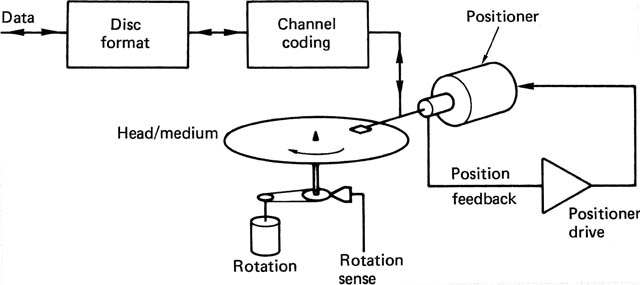
Figure 7.1 shows that, in a disk drive, the data are recorded on a circular track. In hard-disk drives, the disk rotates at several thousand rev/min so that the head-to-disk speed is of the order of 100 miles per hour. At this speed no contact can be tolerated, and the head flies on a boundary layer of air turning with the disk at a height measured in microinches. The longest time it is necessary to wait to access a given data block is a few milliseconds. To increase the storage capacity of the drive without a proportional increase in cost, many concentric tracks are recorded on the disk surface, and the head is mounted on a positioner which can rapidly bring the head to any desired track. Such a machine is termed a moving-head disk drive. An increase in capacity could be obtained by assembling many disks on a common spindle to make a disk pack. The small size of magnetic heads allows the disks to be placed close together. If the positioner is designed so that it can remove the heads away from the disk completely, it can be exchanged. The exchangeable-pack moving-head disk drive became the standard for mainframe and minicomputers for a long time.
Figure 7.1 The rotating store concept. Data on the rotating circular track are repeatedly presented to the head.

Later came the so-called Winchester technology disks, where the disk and positioner formed a compact sealed unit which allowed increased storage capacity but precluded exchange of the disk pack alone.
Disk drive development has been phenomenally rapid. The first flying-head disks were about 3 feet across. Subsequently disk sizes of 14, 8, 5¼ 3½ and 1⅞ inches were developed. Despite the reduction in size, the storage capacity is not compromised because the recording density has increased and continues to increase. In fact there is an advantage in making a drive smaller because the moving parts are then lighter and travel a shorter distance, improving access time.
There are numerous types of optical disk, which have different characteristics. The basic principles of optical disk readout are introduced in section 7.10. Optical disks fall into three broad groups which can usefully be compared.
1 The Compact Disc: its data derivative CD-ROM and the later DVD are examples of a read-only laser disk, which is designed for mass duplication by stamping. They cannot be recorded.
2 Some laser disks can be recorded, but once recorded they cannot be edited or erased because some permanent mechanical or chemical change has been made. These are usually referred to as write-once-read-many (WORM) disks.
3 Erasable optical disks have essentially the same characteristic as magnetic disks, in that new and different recordings can be made in the same track indefinitely, but there is usually a separate erase cycle needed before a new recording can be made since overwrite is not always possible.
Figure 7.2 introduces the essential subsystems of a disk drive which will be discussed here. Magnetic drives and optical drives are similar in that both have a spindle drive mechanism to revolve the disk, and a positioner to give radial access across the disk surface. In the optical drive, the positioner has to carry a collection of lasers, lenses, prisms, gratings and so on, and will be rather larger than a magnetic head. The heavier pickup cannot be accelerated as fast as a magnetic-drive positioner, and access time is slower. A large number of pickups on one positioner makes matters worse. For this reason and because of the larger spacing needed between the disks, multi-platter optical disks are uncommon. Instead ‘juke box’ mechanisms have been developed to allow a large library of optical disks to be mechanically accessed by one or more drives. Access time is sometimes reduced by having more than one positioner per disk; a technique adopted rarely in magnetic drives. A penalty of the very small track pitch possible in laser disks, which gives the enormous storage capacity, is that very accurate track following is needed, and it takes some time to lock onto a track. For this reason tracks on laser disks are usually made as a continuous spiral, rather than the concentric rings of magnetic disks. In this way, a continuous data transfer involves no more than track following once the beginning of the file is located.
Figure 7.2 The main subsystems of a typical disk drive.
Rigid disks are made from aluminium alloy. Magnetic-oxide types use an aluminium oxide substrate, or undercoat, giving a flat surface to which the oxide binder can adhere. Later metallic disks having higher coercivity are electroplated with the magnetic medium. In both cases the surface finish must be extremely good owing to the very small flying height of the head. As the head-to-disk speed and recording density are functions of track radius, the data are confined to the outer areas of the disks to minimize the change in these parameters. As a result, the centre of the pack is often an empty well. In fixed (i.e. non-interchangeable) disks the drive motor is often installed in the centre well.
The information layer of optical disks may be made of a variety of substances, depending on the working principle. This layer is invariably protected beneath a thick transparent layer of glass or polycarbonate.
Exchangeable optical and magnetic disks are usually fitted in protective cartridges. These have various shutters which retract on insertion in the drive to allow access by the drive spindle and heads. Removable packs usually seat on a taper to ensure concentricity and are held to the spindle by a permanent magnet. A lever mechanism may be incorporated into the cartridge to assist their removal.
7.2 Magnetic disks
In all technologies there are specialist terms, and those relating to magnetic disks will be explained here. Figure 7.3 shows a typical multiplatter magnetic disk pack in conceptual form. Given a particular set of coordinates (cylinder, head, sector), known as a disk physical address, one unique data block is defined. A common block capacity is 512 bytes. The subdivision into sectors is sometimes omitted for special applications. A disk drive can be randomly accessed, because any block address can follow any other, but unlike a RAM, at each address a large block of data is stored, rather than a single word.
Figure 7.3 Disk terminology. Surface: one side of a platter. Track: path described on a surface by a fixed head. Cylinder: imaginary shape intersecting all surfaces at tracks of the same radius. Sector: angular subdivision of pack. Block: that part of a track within one sector. Each block has a unique cylinder, head and sector address.

Magnetic disk drives permanently sacrifice storage density in order to offer rapid access. The use of a flying head with a deliberate air gap between it and the medium is necessary because of the high medium speed, but this causes a severe separation loss which restricts the linear density available. The air gap must be accurately maintained, and consequently the head is of low mass and is mounted flexibly.
The aerohydrodynamic part of the head is known as the slipper; it is designed to provide lift from the boundary layer which changes rapidly with changes in flying height. It is not initially obvious that the difficulty with disk heads is not making them fly, but making them fly close enough to the disk surface. The boundary layer travelling at the disk surface has the same speed as the disk, but as height increases, it slows down due to drag from the surrounding air. As the lift is a function of relative air speed, the closer the slipper comes to the disk, the greater the lift will be. The slipper is therefore mounted at the end of a rigid cantilever sprung towards the medium. The force with which the head is pressed towards the disk by the spring is equal to the lift at the designed flying height. Because of the spring, the head may rise and fall over small warps in the disk. It would be virtually impossible to manufacture disks flat enough to dispense with this feature. As the slipper negotiates a warp it will pitch and roll in addition to rising and falling, but it must be prevented from yawing, as this would cause an azimuth error. Downthrust is applied to the aerodynamic centre by a spherical thrust button, and the required degrees of freedom are supplied by a thin flexible gimbal. The slipper has to bleed away surplus air in order to approach close enough to the disk, and holes or grooves are usually provided for this purpose in the same way that pinch rollers on some tape decks have grooves to prevent tape slip.
In exchangeable-pack drives, there will be a ramp on the side of the cantilever which engages a fixed block when the heads are retracted in order to lift them away from the disk surface.
Figure 7.4 shows how disk heads are made. The magnetic circuit of disk heads was originally assembled from discrete magnetic elements. As the gap and flying height became smaller to increase linear recording density, the slipper was made from ferrite, and became part of the magnetic circuit. This was completed by a small C-shaped ferrite piece which carried the coil. Ferrite heads were restricted in the coercivity of disk they could write without saturating. In thin-film heads, the magnetic circuit and coil are both formed by deposition on a substrate which becomes the rear of the slipper.
Figure 7.4 (a) Winchester head construction showing large air bleed grooves. (b) Close-up of slipper showing magnetic circuit on trailing edge. (c) Thin film head is fabricated on the end of the slipper using microcircuit technology.

In a moving-head device it is not practicable to position separate erase, record and playback heads accurately. Erase is by overwriting, and reading and writing are carried out by the same head. The presence of the air film causes severe separation loss, and peak shift distortion is a major problem. The flying height of the head varies with the radius of the disk track, and it is difficult to provide accurate equalization of the replay channel because of this. The write current is often controlled as a function of track radius so that the changing reluctance of the air gap does not change the resulting record flux. Automatic gain control (AGC) is used on replay to compensate for changes in signal amplitude from the head.
Equalization may be used on recording in the form of precompensation, which moves recorded transitions in such a way as to oppose the effects of peak shift in addition to any replay equalization used.
Early disks used FM coding, which was easy to decode, but had a poor density ratio. The invention of MFM revolutionized hard disks, and further progress led to run-length-limited codes such as 2/3 and 2/7 which had a high density ratio without sacrificing the large jitter window necessary to reject peak shift distortion. Partial response is also suited to disks.
Typical drives have several heads, but with the exception of special-purpose parallel-transfer machines, only one head will be active at any one time, which means that the read and write circuitry can be shared between the heads. The read channel usually incorporates AGC, which will be overridden by the control logic between data blocks in order to search for address marks, which are short unmodulated areas of track. As a block preamble is entered, the AGC will be enabled to allow a rapid gain adjustment.
7.3 Accessing the blocks
The servo system required to move the heads rapidly between tracks, and yet hold them in place accurately for data transfer, is a fascinating and complex piece of engineering. In exchangeable-pack drives, the disk positioner moves on a straight axis which passes through the spindle. Motive power is generally by moving-coil drive, because of the small moving mass which this technique permits.
When a drive is track-following, it is said to be detented, in fine mode or in linear mode depending on the manufacturer. When a drive is seeking from one track to another, it can be described as being in coarse mode or velocity mode. These are the two major operating modes of the servo.
Moving-coil actuators do not naturally detent and require power to stay on-track. The servo system needs positional feedback of some kind. The purpose of the feedback will be one or more of the following:
1 to count the number of cylinders crossed during a seek
2 to generate a signal proportional to carriage velocity
3 to generate a position error proportional to the distance from the centre of the desired track
Magnetic and optical drives obtain these feedback signals in different ways. Many positioners incorporate a tacho which may be a magnetic moving-coil type or its complementary equivalent, the moving-magnet type. Both generate a voltage proportional to velocity, and can give no positional information.
A seek is a process where the positioner moves from one cylinder to another. The speed with which a seek can be completed is a major factor in determining the access time of the drive. The main parameter controlling the carriage during a seek is the cylinder difference, which is obtained by subtracting the current cylinder address from the desired cylinder address. The cylinder difference will be a signed binary number representing the number of cylinders to be crossed to reach the target, direction being indicated by the sign. The cylinder difference is loaded into a counter which is decremented each time a cylinder is crossed. The counter drives a DAC which generates an analog voltage proportional to the cylinder difference. As Figure 7.5 shows, this voltage, known as the scheduled velocity, is compared with the output of the carriage-velocity tacho. Any difference between the two results in a velocity error which drives the carriage to cancel the error. As the carriage approaches the target cylinder, the cylinder difference becomes smaller, with the result that the run-in to the target is critically damped to eliminate overshoot.
Figure 7.5 Control of carriage velocity by cylinder difference. The cylinder difference is loaded into the difference counter A. A digital-to-analog convertor generates an analog voltage from the cylinder difference, known as the scheduled velocity. This is compared with the actual velocity from the transducer B in order to generate the velocity error which drives the servo amplifier C.

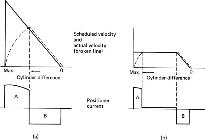
Figure 7.6(a) shows graphs of scheduled velocity, actual velocity and motor current with respect to cylinder difference during a seek. In the first half of the seek, the actual velocity is less than the scheduled velocity, causing a large velocity error which saturates the amplifier and provides maximum carriage acceleration. In the second half of the graphs, the scheduled velocity is falling below the actual velocity, generating a negative velocity error which drives a reverse current through the motor to slow the carriage down. The scheduled deceleration slope clearly cannot be steeper than the saturated acceleration slope. Areas A and B on the graph will be about equal, as the kinetic energy put into the carriage has to be taken out. The current through the motor is continuous, and would result in a heating problem, so to counter this, the DAC is made non-linear so that above a certain cylinder difference no increase in scheduled velocity will occur. This results in the graph of Figure 7.6(b). The actual velocity graph is called a velocity profile. It consists of three regions: acceleration, where the system is saturated; a constant velocity plateau, where the only power needed is to overcome friction; and the scheduled run-in to the desired cylinder. Dissipation is only significant in the first and last regions.
Figure 7.6 In the simple arrangement at (a) the dissipation in the positioner is continuous, causing a heating problem. The effect of limiting the scheduled velocity above a certain cylinder difference is apparent in (b) where heavy positioner current only flows during acceleration and deceleration. During the plateau of the velocity profile, only enough current to overcome friction is necessary. The curvature of the acceleration slope is due to the back EMF of the positioner motor.
The track-following accuracy of a drive positioner will be impaired if there is bearing runout, and so the spindle bearings are made to a high degree of precision.
In order to control reading and writing, the drive control circuitry needs to know which cylinder the heads are on, and which sector is currently under the head. Sector information used to be obtained from a sensor which detects holes or slots cut in the hub of the disk. Modern drives will obtain this information from the disk surface as will be seen. The result is that a sector counter in the control logic remains in step with the physical rotation of the disk. The desired sector address is loaded into a register, which is compared with the sector counter. When the two match, the desired sector has been found. This process is referred to as a search, and usually takes place after a seek. Having found the correct physical place on the disk, the next step is to read the header associated with the data block to confirm that the disk address contained there is the same as the desired address.
7.4 Servo-surface disks
One of the major problems to be overcome in the development of high-density disk drives was that of keeping the heads on-track despite changes of temperature. The very narrow tracks used in digital recording have similar dimensions to the amount a disk will expand as it warms up. The cantilevers and the drive base all expand and contract, conspiring with thermal drift in the cylinder transducer to limit track pitch. The breakthrough in disk density came with the introduction of the servo-surface drive. The position error in a servo-surface drive is derived from a head reading the disk itself. This virtually eliminates thermal effects on head positioning and allows great increases in storage density.
In a multiplatter drive, one surface of the pack holds servo information which is read by the servo head. In a ten-platter pack this means that 5 per cent of the medium area is lost, but this is unimportant since the increase in density allowed is enormous. Using one side of a single-platter cartridge for servo information would be unacceptable as it represents 50 per cent of the medium area, so in this case the servo information can be interleaved with sectors on the data surfaces. This is known as an embedded-servo technique. These two approaches are contrasted in Figure 7.7.
Figure 7.7 In a multiplatter disk pack, one surface is dedicated to servo information. In a single platter, the servo information is embedded in the data on the same surfaces.

The servo surface is written at the time of disk pack manufacture, and the disk drive can only read it. Writing the servo surface has nothing to do with disk formatting, which affects the data storage areas only. As there are exactly the same number of pulses on every track on the servo surface, it is possible to describe the rotational position of the disk simply by counting them. All that is needed is an unique pattern of missing pulses once per revolution to act as an index point, and the sector transducer can also be eliminated.
The advantage of deriving the sector count from the servo surface is that the number of sectors on the disk can be varied. Any number of sectors can be accommodated by feeding the pulse signal through a programmable divider, so the same disk and drive can be used in numerous different applications.
7.5 Winchester technology
In order to offer extremely high capacity per spindle, which reduces the cost per bit, a disk drive must have very narrow tracks placed close together, and must use very short recorded wavelengths, which implies that the flying height of the heads must be small. The so-called Winchester technology is one approach to high storage density. The technology was developed by IBM, and the name came about because the model number of the development drive was the same as that of the famous rifle.
Reduction in flying height magnifies the problem of providing a contaminant-free environment. A conventional disk is well protected whilst inside the drive, but outside the drive the effects of contamination become intolerable.
In exchangeable-pack drives, there is a real limit to the track pitch that can be achieved because of the difficulty or cost of engineering head-alignment mechanisms to make the necessary minute adjustments to give interchange compatibility.
The essence of Winchester technology is that each disk pack has its own set of read/write and servo heads, with an integral positioner. The whole is protected by a dust-free enclosure, and the unit is referred to as a head disk assembly, or HDA.
As the HDA contains its own heads, compatibility problems do not exist, and no head alignment is necessary or provided for. It is thus possible to reduce track pitch considerably compared with exchangeable pack drives. The sealed environment ensures complete cleanliness which permits a reduction in flying height without loss of reliability, and hence leads to an increased linear density. If the rotational speed is maintained, this can also result in an increase in data transfer rate. The HDA is completely sealed, but some have a small filtered port to equalize pressure.
An exchangeable-pack drive must retract the heads to facilitate pack removal. With Winchester technology this is not necessary. An area of the disk surface is reserved as a landing strip for the heads. The disk surface is lubricated, and the heads are designed to withstand landing and take-off without damage. Winchester heads have very large air-bleed grooves to allow low flying height with a much smaller downthrust from the cantilever, and so they exert less force on the disk surface during contact. When the term ‘parking’ is used in the context of Winchester technology, it refers to the positioning of the heads over the landing area.
Disk rotation must be started and stopped quickly to minimize the length of time the heads slide over the medium. This is conveniently achieved with a servo-controlled brushless motor which has dynamic braking ability. A major advantage of contact start/stop is that more than one head can be used on each surface if retraction is not needed. This leads to two gains: first, the travel of the positioner is reduced in proportion to the number of heads per surface, reducing access time; and, second, more data can be transferred at a given detented carriage position before a seek to the next cylinder becomes necessary. This increases the speed of long transfers. Figure 7.8 illustrates the relationships of the heads in such a system.
Figure 7.8 When more than one head is used per surface, the positioner still only requires one servo head. This is often arranged to be equidistant from the read/write heads for thermal stability.
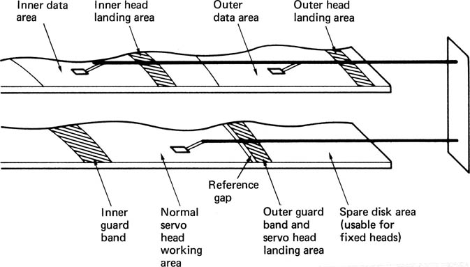
Figure 7.9 shows that rotary positioners are feasible in Winchester drives; they cannot be used in exchangeable-pack drives because of interchange problems. There are some advantages to a rotary positioner. It can be placed in the corner of a compact HDA allowing smaller overall size. The manufacturing cost will be less than a linear positioner because fewer bearings and precision bars are needed. Significantly, a rotary positioner can be made faster since its inertia is smaller. With a linear positioner all parts move at the same speed. In a rotary positioner, only the heads move at full speed, as the parts closer to the shaft must move more slowly. The principle of many rotary positioners is exactly that of a moving-coil ammeter, where current is converted directly into torque.
Figure 7.9 A rotary positioner with two heads per surface. The tolerances involved in the spacing between the heads and the axis of rotation mean that each arm records data in an unique position. Those data can only be read back by the same heads, which rules out the use of a rotary positioner in exchangeable-pack drives. In a head disk assembly the problem of compatibility does not arise.

One characteristic of rotary positioners is that there is a component of windage on the heads which tends to pull the positioner in towards the spindle. Windage can be overcome in rotary positioners by feeding the current cylinder address to a ROM which sends a code to a DAC. This produces an offset voltage which is fed to the positioner driver to generate a torque that balances the windage whatever the position of the heads.
When extremely small track spacing is contemplated, it cannot be assumed that all the heads will track the servo head due to temperature gradients. In this case the embedded-servo approach must be used, where each head has its own alignment patterns. The servo surface is often retained in such drives to allow coarse positioning, velocity feedback and index and write-clock generation, in addition to locating the guard bands for landing the heads.
Winchester drives have been made with massive capacity, but the problem of backup is then magnified, and the general trend has been for the physical size of the drive to come down as the storage density increases in order to improve access time and to facilitate the construction of storage arrays (see section 7.8). Very small Winchester disk drives are now available which plug into standard integrated circuit sockets. These are competing with RAM for memory applications where non-volatility is important.
7.6 The disk controller
A disk controller is a unit which is interposed between the drives and the rest of the system. It consists of two main parts; that which issues control signals to and obtains status from the drives, and that which handles the data to be stored and retrieved. Both parts are synchronized by the control sequencer. The essentials of a disk controller are determined by the characteristics of drives and the functions needed, and so they do not vary greatly. It is desirable for economic reasons to use a commercially available disk controller intended for computers. Such controllers are adequate for still store applications, but cannot support the data rate required for real-time moving video unless data reduction is employed. Disk drives are generally built to interface to a standard controller interface, such as the SCSI bus. The disk controller will then be a unit which interfaces the drive bus to the host computer system.
The execution of a function by a disk subsystem requires a complex series of steps, and decisions must be made between the steps to decide what the next will be. There is a parallel with computation, where the function is the equivalent of an instruction, and the sequencer steps needed are the equivalent of the microinstructions needed to execute the instruction. The major failing in this analogy is that the sequence in a disk drive must be accurately synchronized to the rotation of the disk.
Most disk controllers use direct memory access, which means that they have the ability to transfer disk data in and out of the associated memory without the assistance of the processor. In order to cause a file transfer, the disk controller must be told the physical disk address (cylinder, sector, track), the physical memory address where the file begins, the size of the file and the direction of transfer (read or write). The controller will then position the disk heads, address the memory, and transfer the samples. One disk transfer may consist of many contiguous disk blocks, and the controller will automatically increment the disk-address registers as each block is completed. As the disk turns, the sector address increases until the end of the track is reached. The track or head address will then be incremented and the sector address reset so that transfer continues at the beginning of the next track. This process continues until all the heads have been used in turn. In this case both the head address and sector address will be reset, and the cylinder address will be incremented, which causes a seek. A seek which takes place because of a data transfer is called an implied seek, because it is not necessary formally to instruct the system to perform it. As disk drives are block-structured devices, and the error correction is codeword-based, the controller will always complete a block even if the size of the file is less than a whole number of blocks. This is done by packing the last block with zeros.
The status system allows the controller to find out about the operation of the drive, both as a feedback mechanism for the control process, and to handle any errors. Upon completion of a function, it is the status system which interrupts the control processor to tell it that another function can be undertaken.
In a system where there are several drives connected to the controller via a common bus, it is possible for non data-transfer functions such as seeks to take place in some drives simultaneously with a data transfer in another.
Before a data transfer can take place, the selected drive must physically access the desired block, and confirm this by reading the block header. Following a seek to the required cylinder, the positioner will confirm that the heads are on track and settled. The desired head will be selected, and then a search for the correct sector begins. This is done by comparing the desired sector with the current sector register, which is typically incremented by dividing down servo-surface pulses. When the two counts are equal, the head is about to enter the desired block. Figure 7.10 shows the structure of a typical magnetic disk track. In between blocks are placed address marks, which are areas without transitions which the read circuits can detect. Following detection of the address mark, the sequencer is roughly synchronized to begin handling the block. As the block is entered, the data separator locks to the preamble, and in due course the sync pattern will be found. This sets to zero a counter which divides the data-bit rate by eight, allowing the serial recording to be correctly assembled into bytes, and also allowing the sequencer to count the position of the head through the block in order to perform all the necessary steps at the right time.
Figure 7.10 The format of a typical disk block related to the count process which is used to establish where in the block the head is at any time. During a read the count is derived from the actual data read, but during a write, the count is derived from the write clock.

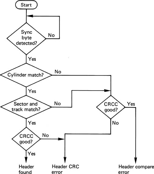
The first header word is usually the cylinder address, and this is compared with the contents of the desired cylinder register. The second header word will contain the sector and track address of the block, and these will also be compared with the desired addresses. There may also be bad-block flags and/or defect-skipping information. At the end of the header is a CRCC which will be used to ensure that the header was read correctly. Figure 7.11 shows a flowchart of the position verification, after which a data transfer can proceed. The header reading is completely automatic. The only time it is necessary formally to command a header to be read is when checking that a disk has been formatted correctly.
Figure 7.11 The vital process of position confirmation is carried out in accordance with the above flowchart. The appropriate words from the header are compared in turn with the contents of the disk-address registers in the subsystem. Only if the correct header has been found and read properly will the data transfer take place.
During the read of a data block, the sequencer is employed again. The sync pattern at the beginning of the data is detected as before, following which the actual data arrive. These bits are converted to byte or sample parallel, and sent to the memory by DMA. When the sequencer has counted the last data-byte off the track, the redundancy for the error-correction system will be following.
During a write function, the header-check function will also take place as it is perhaps even more important not to write in the wrong place on a disk. Once the header has been checked and found to be correct, the write process for the associated data block can begin. The preambles, sync pattern, data block, redundancy and postamble have all to be written contiguously. This is taken care of by the sequencer, which is obtaining timing information from the servo surface to lock the block structure to the angular position of the disk. This should be contrasted with the read function, where the timing comes directly from the data.
When video samples are fed into a disk-based system, from a digital interface or from an A/D convertor, they will be placed in a buffer memory, from which the disk controller will read them by DMA. The continuous-input sample stream will be split up into disk blocks for disk storage.
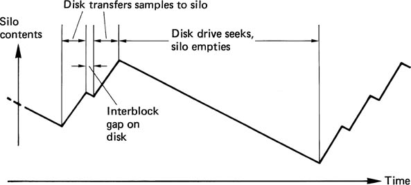
The disk transfers must, by definition, be intermittent, because there are headers between contiguous sectors. Once all the sectors on a particular cylinder have been used, it will be necessary to seek to the next cylinder, which will cause a further interruption to the data transfer. If a bad block is encountered, the sequence will be interrupted until it has passed. The instantaneous data rate of a parallel transfer drive is made higher than the continuous video data rate, so that there is time for the positioner to move whilst the video output is supplied from the FIFO memory. In replay, the drive controller attempts to keep the FIFO as full as possible by issuing a read command as soon as one block space appears in the FIFO. This allows the maximum time for a seek to take place before reading must resume. Figure 7.12 shows the action of the FIFO. Whilst recording, the drive controller attempts to keep the FIFO as empty as possible by issuing write commands as soon as a block of data is present. In this way the amount of time available to seek is maximized in the presence of a continuous video sample input.
Figure 7.12 During a video replay sequence, silo is constantly emptied to provide samples, and is refilled in blocks by the drive.
7.7 Defect handling
The protection of data recorded on disks differs considerably from the approach used on other media in digital video. This has much to do with the intolerance of data processors to errors when compared with video data. In particular, it is not possible to interpolate to conceal errors in a computer program or a data file.
In the same way that magnetic tape is subject to dropouts, magnetic disks suffer from surface defects whose effect is to corrupt data. The shorter wavelengths employed as disk densities increase are affected more by a given size of defect. Attempting to make a perfect disk is subject to a law of diminishing returns, and eventually a state is reached where it becomes more cost-effective to invest in a defect-handling system.
In the construction of bad-block files, a brand-new disk is tested by the operating system. Known patterns are written everywhere on the disk, and these are read back and verified. Following this the system gives the disk a volume name, and creates on it a directory structure which keeps records of the position and size of every file subsequently written. The physical disk address of every block which fails to verify is allocated to a file which has an entry in the disk directory. In this way, when genuine data files come to be written, the bad blocks appear to the system to be in use storing a fictitious file, and no attempt will be made to write there. Some disks have dedicated tracks where defect information can be written during manufacture or by subsequent verification programs, and these permit a speedy construction of the system bad-block file.
7.8 RAID arrays
Whilst the MTBF of a disk drive is very high, it is a simple matter of statistics that when a large number of drives is assembled in a system the time between failures becomes shorter. Disk drives are sealed units and the disks cannot be removed if there is an electronic failure. Even if this were possible the system cannot usually afford downtime whilst such a data recovery takes place.
Consequently any system in which the data are valuable must take steps to ensure data integrity. This is commonly done using RAID (redundant array of inexpensive disks) technology. Figure 7.13 shows that in a RAID array data blocks are spread across a number of drives.
Figure 7.13 In RAID technology, data and redundancy are spread over a number of drives (a). In the case of a drive failure (b) the error-correction system can correct for the loss and continue operation. When the drive is replaced (c) the data can be rewritten so that the system can then survive a further failure.

An error-correcting check symbol (typically Reed-Solomon) is stored on a redundant drive. The error-correction is powerful enough to fully correct any error in the block due to a single failed drive. In RAID arrays the drives are designed to be hot-plugged (replaced without removing power) so if a drive fails it is simply physically replaced with a new one. The error-correction system will rewrite the drive with the data which was lost with the failed unit.
When a large number of disk drives are arrayed together, it is necessary and desirable to spread files across all the drives in a RAID array. Whilst this ensures data integrity, it also means that the data transfer rate is multiplied by the number of drives sharing the data. This means that the data transfer rate can be extremely high and new approaches are necessary to move the data in and out of the disk system.
7.9 Disk servers
The disk controller will automatically divide files up into blocks of the appropriate size for recording. If any partial blocks are left over, these will be zero stuffed. Consequently disk stores are not constrained to files of a particular size. Unlike a DVTR which always stores the same amount of data per field, a disk system can store a different amount of data for each field if needs be.
This means that disks are not standards dependent. A disk system can mix 4:4:4, 4:2:2 and 4:2:0 files and it doesn’t care whether the video is interlaced or not or compressed or not. It can mix 525- and 625-line files and it can mix 4:3 and 16:9 aspect ratios. This an advantage in news systems where compression is used. If a given compression scheme is used at the time of recording e.g. DVCPRO, the video can remain in the compressed data domain when it is loaded onto the disk system for editing. This avoids concatenation of codecs which is generally bad news in compressed systems.
One of the happy consequences of the move to disk drives in production is that the actual picture format used need no longer be fixed. With computer graphics and broadcast video visibly merging, interlace may well be doomed. In the near future it will be possible to use non-interlaced HD cameras, and downconvert to a non-interlaced intermediate-resolution production format.
As production units such as mixers, character generators, paint systems and DVEs become increasingly software driven, such a format is much easier to adopt than in the days of analog where the functionality was frozen into the circuitry. Following production the intermediate format can be converted to any present or future emission standard.
7.10 Optical disk principles
In order to record MO disks or replay any optical disk, a source of monochromatic light is required. The light source must have low noise otherwise the variations in intensity due to the noise of the source will mask the variations due to reading the disk. The requirement for a low-noise monochromatic light source is economically met using a semiconductor laser.
In the LED, the light produced is incoherent or noisy. In the laser, the ends of the semiconductor are optically flat mirrors, which produce an optically resonant cavity. One photon can bounce to and fro, exciting others in synchronism, to produce coherent light. This is known as Light Amplification by Stimulated Emission of Radiation, mercifully abbreviated to LASER, and can result in a runaway condition, where all available energy is used up in one flash. In injection lasers, an equilibrium is reached between energy input and light output, allowing continuous operation with a clean output. The equilibrium is delicate, and such devices are usually fed from a current source. To avoid runaway when temperature change disturbs the equilibrium, a photosensor is often fed back to the current source. Such lasers have a finite life, and become steadily less efficient. The feedback will maintain output, and it is possible to anticipate the failure of the laser by monitoring the drive voltage needed to give the correct output.
Many rerecordable or eraseable optical disks rely on magneto-optics. The storage medium is magnetic, but the writing mechanism is the heat produced by light from a laser; hence the term ‘thermomagneto-optics’. The advantage of this writing mechanism is that there is no physical contact between the writing head and the medium. The distance can be several millimetres, some of which is taken up with a protective layer to prevent corrosion. Originally, this layer was glass, but engineering plastics have now taken over.
The laser beam will supply a relatively high power for writing, since it is supplying heat energy. For reading, the laser power is reduced, such that it cannot heat the medium past the Curie temperature, and it is left on continuously.
Whatever the type of disk being read, it must be illuminated by the laser beam. Some of the light reflected back from the disk re-enters the aperture of the objective lens. The pickup must be capable of separating the reflected light from the incident light. When playing prerecorded disks such as CDs or DVDs, the phase contrast readout process results in a variation of intensity of the light returning to the pickup. When playing MO disks, the intensity does not change, but the magnetic recording on the disk rotates the plane of polarization one way or the other depending on the direction of the vertical magnetization. Figure 7.14(a) shows that a polarizing prism is required to linearly polarize the light from the laser on its way to the disk. Light returning from the disk has had its plane of polarization rotated by approximately 1 degree. This is an extremely small rotation. Figure 7.14(b) shows that the returning rotated light can be considered to be composed of two orthogonal components. Rx is the component which is in the same plane as the illumination and is called the ordinary component and Ry in the component due to the Kerr effect rotation and is known as the magneto-optic component. A polarizing beam splitter mounted squarely would reflect the magneto-optic component Ry very well because it is at right-angles to the transmission plane of the prism, but the ordinary component would pass straight on in the direction of the laser. By rotating the prism slightly a small amount of the ordinary component is also reflected. Figure 7.14(c) shows that when combined with the magneto-optic component, the angle of rotation has increased. Detecting this rotation requires a further polarizing prism or analyser as shown. The prism is twisted such that the transmission plane is at 45° to the planes of Rx and Ry. Thus with an unmagnetized disk, half of the light is transmitted by the prism and half is reflected. If the magnetic field of the disk turns the plane of polarization towards the transmission plane of the prism, more light is transmitted and less is reflected. Conversely if the plane of polarization is rotated away from the transmission plane, less light is transmitted and more is reflected. If two sensors are used, one for transmitted light and one for reflected light, the difference between the two sensor outputs will be a waveform representing the angle of polarization and thus the recording on the disk. This differential analyser eliminates common-mode noise in the reflected beam.
Figure 7.14 A pickup suitable for the replay of magneto-optic disks must respond to very small rotations of the plane of polarization.

High-density recording implies short wavelengths. Using a laser focused on the disk from a distance allows short-wavelength recordings to be played back without physical contact, whereas conventional magnetic recording requires intimate contact and implies a wear mechanism, the need for periodic cleaning, and susceptibility to contamination.
The information layer is read through the thickness of the disk; this approach causes the readout beam to enter and leave the disk surface through the largest possible area. Despite the minute spot size of about 1 micrometre diameter, light enters and leaves through a 1 mm diameter circle. As a result, surface debris has to be three orders of magnitude larger than the readout spot before the beam is obscured. This approach has the further advantage in MO drives that the magnetic head, on the opposite side to the laser pickup, is then closer to the magnetic layer in the disk.
7.11 Focus and tracking systems
The frequency response of the laser pickup and the amount of crosstalk are both a function of the spot size and care must be taken to keep the beam focused on the information layer. If the spot on the disk becomes too large, it will be unable to discern the smaller features of the track, and can also be affected by the adjacent track. Disk warp and thickness irregularities will cause focal-plane movement beyond the depth of focus of the optical system, and a focus servo system will be needed. The depth of field is related to the numerical aperture, which is defined, and the accuracy of the servo must be sufficient to keep the focal plane within that depth, which is typically ±1 mm.
The track pitch of a typical optical disk is of the order of a micrometre, and this is much smaller than the accuracy to which the player chuck or the disk centre hole can be made; on a typical player, runout will swing several tracks past a fixed pickup. The non-contact readout means that there is no inherent mechanical guidance of the pickup and a suitable servo system must be provided.
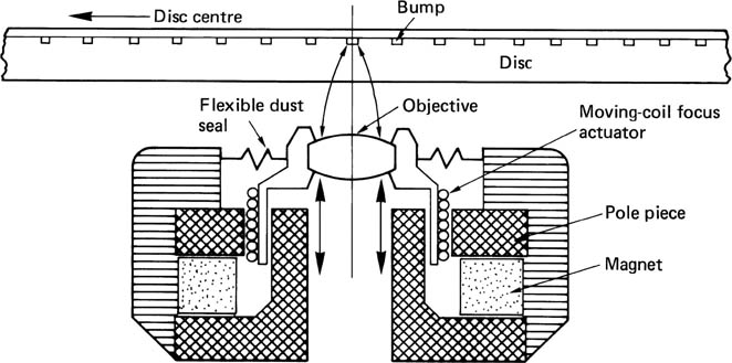
The focus servo moves a lens along the optical axis in order to keep the spot in focus. Since dynamic focus-changes are largely due to warps, the focus system must have a frequency response in excess of the rotational speed. A moving-coil actuator is often used owing to the small moving mass which this permits. Figure 7.15 shows that a cylindrical magnet assembly almost identical to that of a loudspeaker can be used, coaxial with the light beam. Alternatively a moving magnet design can be used. A rare-earth magnet allows a sufficiently strong magnetic field without excessive weight.
Figure 7.15 Moving-coil-focus servo can be coaxial with the light beam as shown.
A focus-error system is necessary to drive the lens. There are a number of ways in which this can be derived, the most common of which will be described here.
Figure 7.16 The cylindrical lens focus method produces an elliptical spot on the sensor whose aspect ratio is detected by a four-quadrant sensor to produce a focus error.
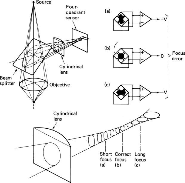
In Figure 7.16 a cylindrical lens is installed between the beam splitter and the photosensor. The effect of this lens is that the beam has no focal point on the sensor. In one plane, the cylindrical lens appears parallel-sided, and has negligible effect on the focal length of the main system, whereas in the other plane, the lens shortens the focal length. The image will be an ellipse whose aspect ratio changes as a function of the state of focus. Between the two foci, the image will be circular. The aspect ratio of the ellipse, and hence the focus error, can be found by dividing the sensor into quadrants. When these are connected as shown, the focus-error signal is generated. The data readout signal is the sum of the quadrant outputs.
Figure 7.17 shows the knife-edge method of determining focus. A split sensor is also required. At (a) the focal point is coincident with the knife-edge, so it has little effect on the beam. At (b) the focal point is to the right of the knife-edge, and rising rays are interrupted, reducing the output of the upper sensor. At (c) the focal point is to the left of the knife-edge, and descending rays are interrupted, reducing the output of the lower sensor. The focus error is derived by comparing the outputs of the two halves of the sensor. A drawback of the knife-edge system is that the lateral position of the knife-edge is critical, and adjustment is necessary. To overcome this problem, the knife edge can be replaced by a pair of prisms, as shown in Figure 7.17(d)-(f). Mechanical tolerances then only affect the sensitivity, without causing a focus offset.
Figure 7.17 (a)-(c) Knife-edge focus-method requires only two sensors, but is critically dependent on knife-edge position. (d)-(f) Twin-prism method requires three sensors (A, B, C), where focus error is (A + C) B. Prism alignment reduces sensitivity without causing focus error.

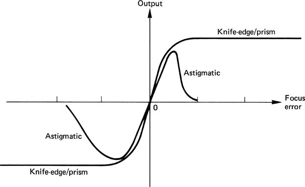
The cylindrical lens method is compared with the knife-edge/prism method in Figure 7.18, which shows that the cylindrical lens method has a much smaller capture range. A focus-search mechanism will be required, which moves the focus servo over its entire travel, looking for a zero crossing. At this time the feedback loop will be completed, and the sensor will remain on the linear part of its characteristic. The spiral track of CD and DVD starts at the inside and works outwards. This was deliberately arranged because there is less vertical runout near the hub, and initial focusing will be easier.
Figure 7.18 Comparison of capture range of knife-edge/prism method and astigmatic (cylindrical lens) system. Knife edge may have range of 1 mm, whereas astigmatic may only have a range of 40 micrometres, requiring a focus-search mechanism.
In addition to the track runout mentioned above, there are further mechanisms which cause tracking error. A warped disk will not present its surface at 90° to the beam, but will constantly change the angle of incidence during two whole cycles per revolution. Owing to the change of refractive index at the disk surface, the tilt will change the apparent position of the track to the pickup, and Figure 7.19 shows that this makes it appear wavy. Warp also results in coma of the readout spot. The disk format specifies a maximum warp amplitude to keep these effects under control. Finally, vibrations induced in the player from outside, particularly in portable and automotive players, will tend to disturb tracking. A track-following servo is necessary to keep the spot centralized on the track in the presence of these difficulties. There are several ways in which a tracking error can be derived.
Figure 7.19 Owing to refraction, the angle of incidence (i) is greater than the angle of refraction (r). Disk warp causes the apparent position of the track (dotted line) to move, requiring the tracking servo to correct.

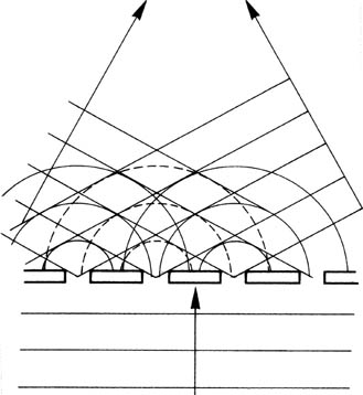
In the three-spot method, two additional light beams are focused on the disk track, one offset to each side of the track centre-line. Figure 7.20 shows that, as one side spot moves away from the track into the mirror area, there is less destructive interference and more reflection. This causes the average amplitude of the side spots to change differentially with tracking error. The laser head contains a diffraction grating which produces the side spots, and two extra photosensors onto which the reflections of the side spots will fall. The side spots feed a differential amplifier, which has a low-pass filter to reject the channel-code information and retain the average brightness difference. Some players use a delay line in one of the side-spot signals whose period is equal to the time taken for the disk to travel between the side spots. This helps the differential amplifier to cancel the channel code.
Figure 7.20 Three-spot method of producing tracking error compares average level of side-spot signals. Side spots are produced by a diffraction grating and require their own sensors.

The side spots are generated as follows. When a wavefront reaches an aperture which is small compared to the wavelength, the aperture acts as a point source, and the process of diffraction can be observed as a spherical wavefront leaving the aperture as in Figure 7.21. Where the wavefront passes through a regular structure, known as a diffraction grating, light on the far side will form new wavefronts wherever radiation is in phase, and Figure 7.22 shows that these will be at an angle to the normal depending on the spacing of the structure and the wavelength of the light. A diffraction grating illuminated by white light will produce a dispersed spectrum at each side of the normal. To obtain a fixed angle of diffraction, monochromatic light is necessary.
Figure 7.21 Diffraction as a plane wave reaches a small aperture.

Figure 7.22 In a diffraction grating, constructive interference can take place at more than one angle for a single wavelength.
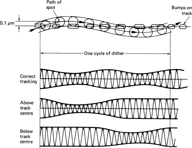
The alternative approach to tracking-error detection is to analyse the diffraction pattern of the reflected beam. The effect of an off-centre spot is to rotate the radial diffraction pattern about an axis along the track. Figure 7.23 shows that, if a split sensor is used, one half will see greater modulation than the other when off-track. Such a system may be prone to develop an offset due either to drift or to contamination of the optics, although the capture range is large. A further tracking mechanism is often added to obviate the need for periodic adjustment. Figure 7.24 shows that in this dither-based system, a sinusoidal drive is fed to the tracking servo, causing a radial oscillation of spot position of about ±50 nm. This results in modulation of the envelope of the readout signal, which can be synchronously detected to obtain the sense of the error. The dither can be produced by vibrating a mirror in the light path, which enables a high frequency to be used, or by oscillating the whole pickup at a lower frequency.
Figure 7.23 Split-sensor method of producing tracking error focuses image of spot onto sensor. One side of spot will have more modulation when off track.

Figure 7.24 Dither applied to readout spot modulates the readout envelope. A tracking error can be derived.
In prerecorded disks there is obviously a track to follow, but in recordable disks provision has to be made for track following during the first recording of a blank disk. This is typically done by pressing the tracks in the form of continuous grooves. The grooves may be produced with a lateral wobble so that the wobble frequency can be used to measure the speed of the track during recording.
7.12 Structure of a DVD player
Figure 7.25 shows the block diagram of a typical DVD player, and illustrates the essential components. The most natural division within the block diagram is into the control/servo system and the data path. The control system provides the interface between the user and the servo mechanisms, and performs the logical interlocking required for safety and the correct sequence of operation.
Figure 7.25 A DVD player’s essential parts. See text for details.

The servo systems include any power-operated loading drawer and chucking mechanism, the spindle-drive servo, and the focus and tracking servos already described. Power loading is usually implemented on players where the disk is placed in a drawer. Once the drawer has been pulled into the machine, the disk is lowered onto the drive spindle, and clamped at the centre, a process known as chucking. In the simpler top-loading machines, the disk is placed on the spindle by hand, and the clamp is attached to the lid so that it operates as the lid is closed.
The lid or drawer mechanisms have a safety switch which prevents the laser operating if the machine is open. This is to ensure that there can be no conceivable hazard to the user. In actuality there is very little hazard in a DVD pickup. This is because the beam is focused a few millimetres away from the objective lens, and beyond the focal point the beam diverges and the intensity falls rapidly. It is almost impossible to position the eye at the focal point when the pickup is mounted in the player, but it would be foolhardy to attempt to disprove this.
The data path consists of the data separator, the de-interleaving and error-correction process followed by a RAM buffer which supplies the MPEG decoder. The data separator converts the EFMplus readout waveform into data. Following data separation the error-correction and de-interleave processes take place. Because of the interleave system, there are two opportunities for correction, first, using the inner code prior to de-interleaving, and second, using the outer code after de-interleaving. In Chapter 6 it was shown that interleaving is designed to spread the effects of burst errors among many different codewords, so that the errors in each are reduced. However, the process can be impaired if a small random error, due perhaps to an imperfection in manufacture, occurs close to a burst error caused by surface contamination. The function of the inner redundancy is to correct single-symbol errors, so that the power of interleaving to handle bursts is undiminished, and to generate error flags for the outer system when a gross error is encountered.
The EFMplus coding is a group code which means that a small defect which changes one channel pattern into another could have corrupted up to eight data bits. In the worst case, if the small defect is on the boundary between two channel patterns, two successive bytes could be corrupted. However, the final odd/even interleave on encoding ensures that the two bytes damaged will be in different inner codewords; thus a random error can never corrupt two bytes in one inner codeword, and random errors are therefore always correctable.
The de-interleave process is achieved by writing sequentially into a memory and reading out using a sequencer. The outer decoder will then correct any burst errors in the data. As MPEG data are very sensitive to error the error-correction performance has to be extremely good.
Following the de-interleave and outer error-correction process an MPEG program stream (see Chapter 5) emerges. Some of the program stream data will be video, some will be audio and this will be routed to the appropriate decoder. It is a fundamental concept of DVD that the bit rate of this program stream is not fixed, but can vary with the difficulty of the program material in order to maintain consistent image quality. The bit rate is changed by changing the speed of the disk. However, there is a complication because the disk uses constant linear velocity rather than constant angular velocity. It is not possible to obtain a particular bit rate with a fixed spindle speed.
The solution is to use a RAM buffer between the transport and the MPEG decoders. The RAM is addressed by counters which are arranged to overflow, giving the memory a ring structure as described in Section 1.7. Writing into the memory is done using clocks derived from the disk whose frequency rises and falls with runout, whereas reading is done by the decoder which, for each picture, will take as much data as is required from the buffer.
The buffer will only function properly if the two addresses are kept apart. This implies that the amount of data read from the disk over the long term must equal the amount of data used by the MPEG decoders. This is done by analysing the address relationship of the buffer. If the disk is turning too fast, the write address will move towards the read address; if the disk is turning too slowly, the write address moves away from the read address. Subtraction of the two addresses produces an error signal which can be fed to the spindle motor.
The speed of the motor is unimportant. The important factor is that the data rate needed by the decoder is correct, and the system will drive the spindle at whatever speed is necessary so that the buffer neither underflows nor overflows.
The MPEG decoder will convert the compressed elementary streams into PCM video and audio and place the pictures and audio blocks into RAM. These will be read out of RAM whenever the time stamps recorded with each picture or audio block match the state of a time stamp counter. If bidirectional coding is used, the RAM readout sequence will convert the recorded picture sequence back to the real-time sequence. The time stamp counter is derived from a crystal oscillator in the player which is divided down to provide the 90 kHz time stamp clock.
As a result, the frame rate at which the disk was mastered will be replicated as the pictures are read from RAM. Once a picture buffer is read out, this will trigger the decoder to decode another picture. It will read data from the buffer until this has been completed and thus indirectly influence the disk speed.
Owing to the use of constant linear velocity, the disk speed will be wrong if the pickup is suddenly made to jump to a different radius using manual search controls. This may force the data separator out of lock, or cause a buffer overflow and the decoder may freeze briefly until this has been remedied.
The control system of a DVD player is inevitably microprocessor-based, and as such does not differ greatly in hardware terms from any other microprocessor-controlled device. Operator controls will simply interface to processor input ports and the various servo systems will be enabled or overridden by output ports. Software, or more correctly firmware, connects the two. The necessary controls are Play and Eject, with the addition in most players of at least Pause and some buttons which allow rapid skipping through the program material.
Although machines vary in detail, the flowchart of Figure 7.26 shows the logic flow of a simple player, from Start being pressed to pictures and sound emerging. At the beginning, the emphasis is on bringing the various servos into operation. Towards the end, the disk subcode is read in order to locate the beginning of the first section of the program material.
Figure 7.26 Simple processes required for a DVD player to operate.

When track-following, the tracking-error feedback loop is closed, but for track crossing, in order to locate a piece of action, the loop is opened, and a microprocessor signal forces the laser head to move. The tracking error becomes an approximate sinusoid as tracks are crossed. The cycles of tracking error can be counted as feedback to determine when the correct number of tracks have been crossed. The ‘mirror’ signal obtained when the readout spot is half a track away from target is used to brake pickup motion and re-enable the track-following feedback.
7.13 Non-linear video editing
Non-linear editing takes advantage of the freedom to store digitized image data in any suitable medium and the signal-processing techniques developed in computation. The images may have originated on film or video. Recently images which have been synthesized by computer have been added. Although aesthetically film and video have traditionally had little in common, from a purely technological standpoint many of the necessary processes are similar.
In all types of editing the goal is the appropriate sequence of material at the appropriate time. In an ideal world the difficulty and cost involved in creating the perfect edited work are discounted. In practice there is economic pressure to speed up the editing process and to use cheaper media. Editors will not accept new technologies if they form an obstacle to the creative process, but if a new approach to editing takes nothing away, it will be considered. If something is added, such as freedom or flexibility, so much the better.
When there was only film or video tape editing, it did not need a qualifying name. Now that images are stored as data, alternative storage media have become available which allow editors to reach the same goal but using different techniques. Whilst digital VTR formats copy their analog predecessors and support field-accurate editing on the tape itself, in all other digital editing samples from various sources are brought from the storage media to various pages of RAM. The edit is viewed by selectively processing two (or more) sample streams retrieved from RAM. Thus the nature of the storage medium does not affect the form of the edit in any way except the amount of time needed to execute it.
Tapes only allow serial access to data, whereas disks and RAM allow random access and so can be much faster. Editing using random access storage devices is very powerful as the shuttling of tape reels is avoided. The technique is sometimes called non-linear editing. This is not a very helpful name, as in these systems the editing itself is performed in RAM in the same way as before. In fact it is only the time axis of the storage medium which is non-linear.
7.14 The structure of a workstation
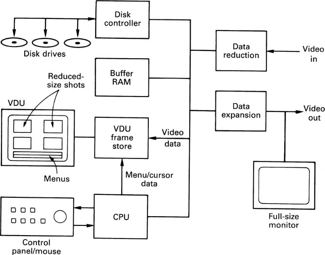
Figure 7.27 shows the general arrangement of a hard disk-based workstation. The VDU in such devices has a screen which is a montage of many different signals, each of which appear in windows. In addition to the video windows there will be a number of alphanumeric and graphic display areas required by the control system. There will also be a cursor which can be positioned by a trackball or mouse. The screen is refreshed by a framestore which is read at the screen refresh rate. The framestore can be simultaneously written by various processes to produce a windowed image. In addition to the VDU, there may be a second screen which reproduces full-size images for preview purposes.
Figure 7.27 A hard-disk-based workstation. Note the screen which can display numerous clips at the same time.
A master timing generator provides reference signals to synchronize the internal processes. This also produces an external reference to which source devices such as VTRs can lock. The timing generator may free-run in a standalone system, or genlock to station reference to allow playout to air.
Digital inputs and outputs are provided, along with optional convertors to allow working in an analog environment. In many workstations, compression is employed, and the appropriate coding and decoding logic will be required adjacent to the inputs and outputs. With mild compresssion, the video output of the machine may be used directly for some purposes. This is known as on-line editing. Alternatively a high compression factor may be used, and the editor is then used only to create an edit decision list (EDL). This is known as off-line editing. The EDL is then used to control automatic editing of the full bandwidth source material, probably on tape.
Disk-based workstations fall into two categories depending on the relative emphasis of the vertical or horizontal aspects of the process. High-end postproduction emphasizes the vertical aspect of the editing as a large number of layers may be used to create the output image. The length of such productions is generally quite short and so disk capacity is not an issue and data reduction will not be employed. In contrast, a general-purpose editor used for television program or film production will emphasize the horizontal aspect of the task. Extended recording ability will be needed, and data reduction is more likely.
The machine will be based around a high data rate bus, connecting the I/O, RAM, disk subsystem and the processor. If magnetic disks are used, these will be Winchester types, because they offer the largest capacity. Exchangeable magneto-optic disks may also be supported.
Before any editing can be performed, it is necessary to have source material on-line. If the source material exists on MO disks with the appropriate file structure, these may be used directly. Otherwise it will be necessary to input the material in real time and record it on magnetic disks via the compression system. In addition to recording the compressed source video, reduced versions of each field may also be recorded which are suitable for the screen windows.
Inputting the image data from film rushes requires telecine to disk transfer. Inputting from video tape requires dubbing. Both are time-consuming processes.
Time can be saved by involving the disk system at an early stage. In video systems, the disk system can record camera video and timecode alongside the VTRs. Editing can then begin as soon as shooting finishes. In film work, it is possible to use video-assisted cameras where a video camera runs from the film camera viewfinder. During filming, the video is recorded on disk and both record the same timecode. Once more, editing can begin as soon as shooting is finished.
7.15 Locating the edit point
Digital editors must simulate the ‘rock and roll’ process of edit-point location in VTRs or flatbeds where the tape or film is moved to and fro by the action of a shuttle knob, jog wheel or joystick. Whilst DVTRs with track-following systems can work in this way, disks cannot. Disk drives transfer data intermittently and not necessarily in real time. The solution is to transfer the recording in the area of the edit point to RAM in the editor. RAM access can take place at any speed or direction and the precise edit point can then be conveniently found by monitoring signals from the RAM. In a window-based display, a source recording is attributed to a particular window, and will be reproduced within that window, with timecode displayed adjacently.
Figure 7.28 shows how the area of the edit point is transferred to the memory. The source device is commanded to play, and the operator watches the replay in the selected window. The same samples are continuously written into a memory within the editor. This memory is addressed by a counter which repeatedly overflows to give the memory a ring-like structure rather like that of a timebase corrector, but somewhat larger. When the operator sees the rough area in which the edit is required, he will press a button. This action stops the memory writing, not immediately, but one half of the memory contents later. The effect is then that the memory contains an equal number of samples before and after the rough edit point. Once the recording is in the memory, it can be accessed at leisure, and the constraints of the source device play no further part in the edit-point location.
Figure 7.28 The use of a ring memory which overwrites allows storage of samples before and after the coarse edit point.

There are a number of ways in which the the memory can be read. If the field address in memory is supplied by a counter which is clocked at the appropriate rate, the edit area can be replayed at normal speed, or at some fraction of normal speed repeatedly. In order to simulate the analog method of finding an edit point, the operator is provided with a scrub wheel or rotor, and the memory field address will change at a rate proportional to the speed with which the rotor is turned, and in the same direction. Thus the recording can be seen forward or backward at any speed, and the effect is exactly that of turning the wheel on a flatbed or VTR.
If the position of the jog address pointer through the memory is compared with the addresses of the ends of the memory, it will be possible to anticipate that the pointer is about to reach the end of the memory. A disk transfer can be performed to fetch new data further up the time axis, so that it is possible to jog an indefinite distance along the source recording in a manner which is transparent to the user.
Samples which will be used to make the master recording need never pass through these processes; they are solely to assist in the location of the edit points.
The act of pressing the coarse edit-point button stores the timecode of the source at that point, which is frame-accurate. As the rotor is turned, the memory address is monitored, and used to update the timecode.
Before the edit can be performed, two edit points must be determined, the outpoint at the end of the previously recorded signal, and the in-point at the beginning of the new signal. The second edit point can be determined by moving the cursor to a different screen window in which video from a different source is displayed. The jog wheel will now roll this material to locate the second edit point while the first source video remains frozen in the deselected window. The editor’s microprocessor stores these in an EDL in order to control the automatic assemble process.
It is also possible to locate a rough edit point by typing in a previously noted timecode, and the image in the window will automatically jump to that time. In some systems, in addition to recording video and audio, there may also be text files locked to timecode which contain the dialog. Using these systems one can allocate a textual dialog display to a further window and scroll down the dialog or search for a key phrase as in a word processor. Unlike a word processor, the timecode pointer from the text access is used to jog the video window. As a result, an edit point can be located in the video if the actor’s lines at the desired point are known.
7.16 Editing with disk drives
Using one or other of the above methods, an edit list can be made which contains an in-point, an out-point and a filename for each of the segments of video which need to be assembled to make the final work, along with a timecode-referenced transition command and period for the vision mixer. This edit list will also be stored on the disk. When a preview of the edited work is required, the edit list is used to determine what files will be necessary and when, and this information drives the disk controller.
Figure 7.29 shows the events during an edit between two files. The edit list causes the relevant blocks from the first file to be transferred from disk to memory, and these will be read by the signal processor to produce the preview output. As the edit point approaches, the disk controller will also place blocks from the incoming file into the memory. In different areas of the memory there will be simultaneously the end of the outgoing recording and the beginning of the incoming recording. Before the edit point, only pixels from the outgoing recording are accessed, but as the transition begins, pixels from the incoming recording are also accessed, and for a time both data streams will be input to the vision mixer according to the transition period required. The output of the signal processor becomes the edited preview material, which can be checked for the required subjective effect. If necessary the in- or out-points can be trimmed, or the crossfade period changed, simply by modifying the edit-list file. The preview can be repeated as often as needed, until the desired effect is obtained. At this stage the edited work does not exist as a file, but is re-created each time by a further execution of the EDL. Thus a lengthy editing session need not fill up the disks.
Figure 7.29 Sequence of events for a hard-disk edit. See text for details.

It is important to realize that at no time during the edit process were the original files modified in any way. The editing was done solely by reading the files. The power of this approach is that if an edit list is created wrongly, the original recording is not damaged, and the problem can be put right simply by correcting the edit list. The advantage of a disk-based system for such work is that location of edit points, previews and reviews are all performed almost instantaneously, because of the random access of the disk. This can reduce the time taken to edit a program to a fraction of that needed with a tape machine.
During an edit, the disk controller has to provide data from two different files simultaneously, and so it has to work much harder than for a simple playback. If there are many close-spaced edits, the controller and drives may be hard-pressed to keep ahead of real time, especially if there are long transitions, because during a transition a vertical edit is taking place between two video signals and the source data rate is twice as great as during replay. A large buffer memory helps this situation because the drive can fill the memory with files before the edit actually begins, and thus the instantaneous sample rate can be met by allowing the memory to empty during disk-intensive periods.
Some drives rotate the sector addressing from one cylinder to the next so that the drive does not lose a revolution when it moves to the next cylinder. Disk-editor performance is usually specified in terms of peak editing activity which can be achieved, but with a recovery period between edits. If an unusually severe editing task is necessary where the drive just cannot access files fast enough, it will be necessary to rearrange the files on the disk surface so that files which will be needed at the same time are on nearby cylinders. An alternative is to spread the material between two or more drives so that overlapped seeks are possible.
Once the editing is finished, it will generally be necessary to transfer the edited material to form a contiguous recording so that the source files can make way for new work. In off-line editing, the source files already exist on tape or film and all that is needed is the EDL; the disk files can simply be erased. In on-line editing the disks hold original recordings and they will need to be backed up to tape if they will be required again. In large broadcast systems, the edited work can be broadcast directly from the disk file server. In smaller systems it will be necessary to output to some removable medium, since the Winchester drives in the editor have fixed media.